1
21 CHEPSTOW VILLAS, LONDON
PLANNING COMPLIANCE REPORT
Report 12602.PCR.01
For:
Joseph Miro
21 Chepstow Villas
London
W11 3DZ
Site Address
Report Date
21 Chepstow Villas,
London
14/05/2015
Revision History
KP Acoustics
12602.PCR.01
14 May 2015
CONTENTS
1.0
INTRODUCTION .......................................................................................................................... 2
2.0
ENVIRONMENTAL NOISE SURVEY AND EQUIPMENT ................................................................. 2
2.1
Procedure ............................................................................................................................................... 2
2.2
Equipment .............................................................................................................................................. 2
3.0
RESULTS ...................................................................................................................................... 3
4.0
NOISE CRITERIA .......................................................................................................................... 3
5.0
DISCUSSION ................................................................................................................................ 3
5.1
Objective overview................................................................................................................................. 4
6.0
CONCLUSION .............................................................................................................................. 5
List of Attachments
12602.SP1
12602.TH1
Appendix A
Appendix B
Appendix C
Indicative Site Plan Showing Noise Monitoring Position
Environmental Noise Time History
Glossary of Acoustic Terminology
Acoustic Calculations
Anti-Vibration Mounting Specification Reference Document
KP Acoustics
1.0
12602.PCR.01
14 May 2015
INTRODUCTION
KP Acoustics Ltd, Britannia House, 11 Glenthorne Road, London, W6 0LH, has been commissioned
by Joseph Miro, 21 Chepstow Villas, London, to undertake a noise impact assessment of the
proposed plant installation at 21 Chepstow Villas, London. The background noise levels measured
will be used to determine daytime and night-time noise emission criteria for the heating and
cooling condensers.
This report presents the overall methodology and results from the environmental survey followed
by calculations to demonstrate the feasibility of the plant installation to satisfy the emissions
criterion at the closest noise-sensitive receiver and outline mitigation measures as appropriate.
2.0
ENVIRONMENTAL NOISE SURVEY AND EQUIPMENT
2.1
Procedure
Automated noise monitoring was undertaken by KP Acoustics Ltd at the position shown in Site Plan
12602.SP1. This location was chosen in order to collect representative noise data in relation to the
nearest noise sensitive receiver relative to the proposed plant installation. Continuous automated
monitoring was undertaken for the duration of the survey between 13:15 on 5 May 2015 and 12:45
on 6 May 2015.
Initial inspection of the site revealed that the background noise profile at the monitoring location
was dominated by road traffic noise from the surrounding roads.
The weather during the course of the survey was generally dry with wind speeds within acceptable
tolerances and therefore suitable for the measurement of environmental noise. The measurement
procedure complied with ISO 1996-2:2007 Acoustics “Description, measurement and assessment of
environmental noise - Part 2: Determination of environmental noise levels”.
2.2
Equipment
The equipment calibration was verified before and after the survey and no calibration irregularities
were observed.
The equipment used was as follows.
•
1 No. Svantek Type 957 Class 1 Sound Level Meter
•
B&K Type 4231 Class 1 Calibrator
12602: 21 CHEPSTOW VILLAS, LONDON
Planning Compliance Report
Page 2 of 5
KP Acoustics
3.0
12602.PCR.01
14 May 2015
RESULTS
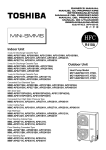
The results from the continuous noise monitoring are shown as a time history of LAeq, LAmax, LA10 and
LA90 averaged over 5 minute sample periods shown in Figure 12602.TH1.
Minimum background noise levels are shown in Table 3.1.
Minimum background noise level
LA90: 5min dB(A)
Daytime (07:00-23:00)
41
Night-time (23:00-07:00)
34
Table 3.1: Minimum measured background noise levels
4.0
NOISE CRITERIA
We propose to set the noise criteria for the noise emissions of the new plant in this instance, so
that the ’A’ weighted sound pressure level from the plant, when operating at its noisiest, shall not
at any time exceed a value of 10 dB below the external background noise, at a point 1 metre
outside the window of the closest receiver.
We therefore propose to set the noise criteria (at 10dB below minimum background noise) as
shown in Table 4.1 in order to comply with the above requirement.
Noise criterion at nearest
receiver
Daytime
Night-time
(07:00 to 23:00)
(23:00 to 07:00)
31 dB(A)
24 dB(A)
(10dB below minimum LA90)
Table 4.1: Proposed Noise Emissions Criteria
As the units could be operated during the daytime or night-time, the criterion of 24dB(A) will be
used to ensure the amenity of the closest receiver will be protected.
5.0
DISCUSSION
It is understood that the plant installation is comprised of the following units:
•
Toshiba MCY-MAP0401HT (2 No.)
•
Toshiba RAV-SM563AT-E (1 No.)
12602: 21 CHEPSTOW VILLAS, LONDON
Planning Compliance Report
Page 3 of 5
KP Acoustics
12602.PCR.01
14 May 2015
The closest noise sensitive receivers to the proposed plant units will be a residential window
located approximately 5m from the units.
The sound pressure levels (at 1m) as provided by the manufacturers for these units are shown in
Table 5.1.
Sound Pressure Level (dB) in each Frequency Band
Unit
63Hz
125Hz
Toshiba MCY-MAP0401HT
Toshiba RAV-SM563AT-E
250Hz
500Hz
1kHz
2kHz
4kHz
8kHz
32
28
No spectral data available – 50 dB(A)
50
52
50
46
42
38
Table 5.1 Manufacturer’s Sound Pressure Levels (at 1m)
The attenuation levels as provided by the acoustic louvre are shown in Table 5.2.
Attenuation provided (dB) in each Frequency Band
Mitigation Type
63Hz
125Hz
250Hz
500Hz
1kHz
2kHz
4kHz
8kHz
Model AL1515 Acoustic Louvre
-4
-4
-5
-8
-12
-16
-15
-12
Table 5.2 Spectral attenuation provided by acoustic louvre
5.1
Objective overview
Taking all acoustic corrections into consideration, including distance corrections, the noise level
expected at the closest residential window would be as shown in Table 5.3. Detailed calculations
are shown in Appendix B.
Noise Level at Receiver
Receiver - Nearest
Noise Sensitive Window
Criterion
Night-time
24dB(A)
st
(Residential Window on 1 Floor)
24dB(A)
Table 5.3 Predicted noise level and criterion at nearest noise sensitive location
As shown in Appendix B and Table 5.3, transmission of noise to the nearest sensitive windows due
to the effects of the plant installation would satisfy the emissions criterion set, provided the
acoustic louvres are installed.
12602: 21 CHEPSTOW VILLAS, LONDON
Planning Compliance Report
Page 4 of 5
KP Acoustics
6.0
12602.PCR.01
14 May 2015
CONCLUSION
An environmental noise survey has been undertaken at 21 Chepstow Villas, London, by KP
Acoustics Ltd between 5/5/2015 and 6/5/2015, in order to assess noise levels in the area of the
proposed development. The results of the survey have enabled criteria to be set for noise
emissions.
Using manufacturer noise data, noise levels are predicted at the nearby noise sensitive receivers
for compliance with current requirements.
Calculations undertaken by KP Acoustics Ltd. show that noise emissions from the proposed plant
unit installation would meet the criteria set, provided a noise control strategy is adopted in the
form of acoustic louvres for the plant units.
Report by
Checked by
Kenny Macleod AMIOA
Kyriakos Papanagiotou MIOA
KP Acoustics Ltd
KP Acoustics Ltd
12602: 21 CHEPSTOW VILLAS, LONDON
Planning Compliance Report
Page 5 of 5
Noise Survey Monitoring Position
Title:
Indicative site plan showing noise monitoring positions.
Date: 12 May 2015
FIGURE 12602.SP1
21 Chepstow Villas, London
Environmental Noise Time History
5th May to 6th May 2015
130
110
LAeq
Level (dB re 2x10⁻⁵ Pa)
90
LA10
LAmax
LA90
70
50
30
10
Time
Figure 12602.TH1
APPENDIX A
GENERAL ACOUSTIC TERMINOLOGY
Decibel scale - dB
In practice, when sound intensity or sound pressure is measured, a logarithmic scale is used in which
the unit is the ‘decibel’, dB. This is derived from the human auditory system, where the dynamic
range of human hearing is so large, in the order of 1013 units, that only a logarithmic scale is the
sensible solution for displaying such a range.
Decibel scale, ‘A’ weighted - dB(A)
The human ear is less sensitive at frequency extremes, below 125Hz and above 16Khz. A sound level
meter models the ears variable sensitivity to sound at different frequencies. This is achieved by
building a filter into the Sound Level Meter with a similar frequency response to that of the ear, an
A-weighted filter where the unit is dB(A).
Leq
The sound from noise sources often fluctuates widely during a given period of time. An average
value can be measured, the equivalent sound pressure level Leq. The Leq is the equivalent sound level
which would deliver the same sound energy as the actual fluctuating sound measured in the same
time period.
L10
This is the level exceeded for no more than 10% of the time. This parameter is often used as a “not
to exceed” criterion for noise.
L90
This is the level exceeded for no more than 90% of the time. This parameter is often used as a
descriptor of “background noise” for environmental impact studies.
Lmax
This is the maximum sound pressure level that has been measured over a period.
Octave Bands
In order to completely determine the composition of a sound it is necessary to determine the sound
level at each frequency individually. Usually, values are stated in octave bands. The audible
frequency region is divided into 11 such octave bands whose centre frequencies are defined in
accordance with international standards. These centre frequencies are: 16, 31.5, 63, 125, 250, 500,
1000, 2000, 4000, 8000 and 16000 Hertz.
Environmental noise terms are defined in BS7445, Description and Measurement of Environmental
Noise.
Glossary of Acoustic Terminology
APPENDIX A
APPLIED ACOUSTIC TERMINOLOGY
Addition of noise from several sources
Noise from different sound sources combines to produce a sound level higher than that from any
individual source. Two equally intense sound sources operating together produce a sound level
which is 3dB higher than a single source and 4 sources produce a 6dB higher sound level.
Attenuation by distance
Sound which propagates from a point source in free air attenuates by 6dB for each doubling of
distance from the noise source. Sound energy from line sources (e.g. stream of cars) drops off by
3dB for each doubling of distance.
Subjective impression of noise
Hearing perception is highly individualised. Sensitivity to noise also depends on frequency content,
time of occurrence, duration of sound and psychological factors such as emotion and expectations.
The following table is a guide to explain increases or decreases in sound levels for many scenarios.
Change in sound level (dB)
1
3
6
10
Change in perceived loudness
Imperceptible
Just barely perceptible
Clearly noticeable
About twice as loud
Transmission path(s)
The transmission path is the path the sound takes from the source to the receiver. Where multiple
paths exist in parallel, the reduction in each path should be calculated and summed at the receiving
point. Outdoor barriers can block transmission paths, for example traffic noise. The effectiveness of
barriers is dependent on factors such as its distance from the noise source and the receiver, its
height and construction.
Ground-borne vibration
In addition to airborne noise levels caused by transportation, construction, and industrial sources
there is also the generation of ground-borne vibration to consider. This can lead to structure-borne
noise, perceptible vibration, or in rare cases, building damage.
Sound insulation - Absorption within porous materials
Upon encountering a porous material, sound energy is absorbed. Porous materials which are
intended to absorb sound are known as absorbents, and usually absorb 50 to 90% of the energy and
are frequency dependent. Some are designed to absorb low frequencies, some for high frequencies
and more exotic designs being able to absorb very wide ranges of frequencies. The energy is
converted into both mechanical movement and heat within the material; both the stiffness and
mass of panels affect the sound insulation performance.
Glossary of Acoustic Terminology
KP Acoustics
12602.PCR.01
12 May 2015
APPENDIX B
21 Chepstow Villas, London
PLANT UNIT EMISSIONS CALCULATIONS
Source: Proposed Plant Installation
Receiver: Nearest Residential Window
63
125
250
Frequency, Hz
500
1k
2k
4k
8k
dB(A)
Sound Pressure Level (at 1m)
No spectral data available
MCY-MAP0401HT
Correction for reflections, dB
Distance correction to receiver, dB (10m)
Correction for number of units (2 No.)
Attenuation from Acoustic Louvre, dB
Attenuation from screening, dB
Total Sound Pressure level from MCY-MAP0401HT
RAV-SM563AT-E
Correction for reflections, dB
Distance correction to receiver, dB (5m)
Attenuation from Acoustic Louvre, dB
Attenuation from screening, dB
Total Sound Pressure level from RAV-SM563AT-E
50
3
-14
-4
-5
30
52
3
-14
-4
-5
32
50
3
-14
-5
-6
28
46
3
-14
-8
-7
20
42
3
-14
-12
-8
11
38
3
-14
-16
-10
1
50
3
-20
3
-11
-10
15
32
3
-14
-15
-12
-6
Sound Pressure Level 1m from Closest Noise Sensitive Receiver
28
3
-14
-12
-14
-9
23
24
Design Criterion
24
APPENDIX C
ANTI-VIBRATION MOUNTING SPECIFICATION REFERENCE DOCUMENT
1.0
General
1.1
All mountings shall provide the static deflection, under the equipment weight, shown in
the schedules. Mounting selection should allow for any eccentric load distribution or
torque reaction, so that the design deflection is achieved on all mountings under the
equipment, under operating conditions.
1.2
It is the supplier's responsibility to ensure that all mountings offered are suitable for the
loads, operating and environmental conditions which will prevail. Particular attention
should be paid to mountings which will be exposed to atmospheric conditions to prevent
corrosion.
1.3
All mountings shall be colour coded, or otherwise marked, to indicate their load capacity,
to facilitate identification during installation.
Where use of resilient supports allows omission of pipe flexible connections for
vibration/noise isolation, it shall be the Mechanical Service Consultant's or Contractor's
responsibility to decide whether such devices are required to compensate for
misalignment or thermal strain.
2.1
Type A Mounting (Caged Spring Type)
2.1.1
Each mounting shall consist of cast or fabricated telescopic top and bottom housings
enclosing one or more helical steel springs as the principle isolation elements, and shall
incorporate a built-in levelling device. The housing should be designed to permit visual
inspection of the springs after installation, i.e. the spring must not be totally enclosed.
2.1.2
The springs shall have an outside diameter of not less than 75% of the operating height,
and be selected to have at least 50% overload capacity before becoming coil-bound.
2.1.3
The bottom plate of each mounting shall have bonded to it a rubber/neoprene pad
designed to attenuate any high frequency energy transmitted by the springs.
2.1.4
Mountings incorporating snubbers or restraining devices shall be designed so that the
snubbing, damping or restraining mechanism is capable of being adjusted to have no
significant effect during the normal running of the isolated machine.
2.1.5
All nuts, bolts or other elements used for adjustment of a mounting shall incorporate
locking mechanisms to prevent the isolator going out of adjustment as a result of vibration
or accidental or unauthorised tampering.
2.2
Type B Mounting (Open Spring Type)
2.2.1
Each mounting shall consist of one or more helical steel springs as the principal isolation
elements, and shall incorporate a built-in levelling device.
2.2.2
The springs shall be fixed or otherwise securely located to cast or fabricated top and
bottom plates, shall have an outside diameter of not less than 75% of the operating height,
and shall be selected to have at least 50% overload capacity before becoming coil-bound.
2.2.3
The bottom plate shall have bonded to it a rubber/ neoprene pad designed to attenuate
any high frequency energy transmitted by the springs.
Anti-Vibration Mounting Specification Reference Document
APPENDIX C
2.3
Type C Mounting (Rubber/Neoprene Type)
Each mounting shall consist of a steel top plate and base plate completely embedded in oil
resistant rubber/neoprene. Each mounting shall be capable of being fitted with a levelling
device, and should have bolt holes in the base plate and a threaded metal insert in the top
plate so that they can be bolted to the floor and equipment where required.
3.0
Plant Bases
3.1
Type A Bases (A.V. Rails)
An A.V. Rail shall comprise a steel beam with two or more height-saving brackets. The
steel sections must be sufficiently rigid to prevent undue strain in the equipment and if
necessary should be checked by the Structural Engineer.
3.2
Type B Bases (Steel Plant Bases)
Steel plant bases shall comprise an all-welded steel framework of sufficient rigidity to
provide adequate support for the equipment, and fitted with isolator height saving
brackets. The frame depth shall be approximately 1/10 of the longest dimension of the
equipment with a minimum of 150 mm. This form of base may be used as a composite
A.V. rail system.
3.3
Type C Bases (Concrete Inertia Base: for use with steel springs)
These shall consist of an all-welded steel pouring frame-work with height saving brackets,
and a frame depth of approximately 1/12 of the longest dimension of the equipment, with
a minimum of 100 mm. The bottom of the pouring frame should be blanked off, and
concrete (2300 kg/m3) poured in over steel reinforcing rods positioned 35 mm above the
bottom. The inertia base should be sufficiently large to provide support for all parts of the
equipment, including any components which over-hang the equipment base, such as
suction and discharge elbows on centrifugal pumps.
Anti-Vibration Mounting Specification Reference Document
OWNERS MANUAL
MANUEL DU PROPRIETAIRE
BETRIEBSANLEITUNG
MANUALE DEL PROPRIETARIO
MANUAL DEL PROPIETARIO
MANUAL DO UTILIZADOR
GEBRUIKSAANWIJZING
ÏÄÇÃÉÅÓ ×ÑÇÓÇÓ
Indoor Unit
4-way Air Discharge Cassette Type
MMU-AP0071MH, AP0091MH, AP0121MH, AP0151MH, AP0181MH,
MMU-AP0091H, AP0121H, AP0151H, AP0181H, AP0241H,
MMU-AP0271H, AP0301H, AP0361H, AP0481H
2-way Air Discharge Cassette Type
MMU-AP0071WH, AP0091WH, AP0121WH,
MMU-AP0151WH, AP0181WH, AP0241WH,
MMU-AP0271WH, AP0301WH
Outdoor Unit
1-way Air Discharge Cassette Type
MMU-AP0071YH, AP0091YH, AP0121YH,
MMU-AP0152SH, AP0182SH, AP0242SH
Heat Pump Model
MCY-MAP0401HT, HT2D,
MCY-MAP0501HT, HT2D,
MCY-MAP0601HT, HT2D
Concealed Duct Standard Type
MMD-AP0071BH, AP0091BH, AP0121BH, AP0151BH, AP0181BH,
MMD-AP0241BH, AP0271BH, AP0301BH, AP0361BH, AP0481BH
Slim Duct Type
MMD-AP0071SPH(SH), AP0091SPH(SH), AP0121SPH(SH),
MMD-AP0151SPH(SH), AP0181SPH(SH)
Concealed Duct High Static Pressure Type
MMD-AP0181H, AP0241H, AP0271H, AP0361H, AP0481H
Under Ceiling Type
MMC-AP0151H, AP0181H, AP0241H, AP0271H, AP0361H, AP0481H
High Wall Type
MMK-AP0071H, AP0072H, AP0091H, AP0092H, AP0121H,
MMK-AP0122H, AP0151H, AP0181H, AP0241H
Floor Standing Cabinet Type
MML-AP0071H, AP0091H, AP0121H,
MML-AP0151H, AP0181H, AP0241H
Floor Standing Concealed Type
MML-AP0071BH, AP0091BH, AP0121BH,
MML-AP0151BH, AP0181BH, AP0241BH
Floor Standing Type
MMF-AP0151H, AP0181H, AP0241H,
MMF-AP0271H, AP0361H, AP0481H
ADOPTION OF NEW REFRIGERANT
This Air Conditioner is a new type which adopts a new
refrigerant HFC (R410A) instead of the conventional
refrigerant R22 in order to prevent destruction of the
ozone layer.
UTILISATION DU NOUVEAU REFRIGERANT
Ce climatiseur est d’un type inédit qui utilise le nouveau
réfrigérant HFC (R410A) au lieu du réfrigérant
traditionnel R22, afin d’éviter la destruction de la couche
d’ozone.
EINFÜHRUNG EINES NEUEN KÜHLMITTELS
Dies ist ein neuartiges Klimagerät. Anstatt des
herkömmlichen Kühlmittels R22 verwendet es das neue
ozonschicht-schonende HFC Kühlmittel R410A.
ADOZIONE DI UN NUOVO REFRIGERANTE
Questo condizionatore d'aria è di un tipo nuovo che
adotta un nuovo refrigerate HFC (R410A) al posto del
refrigerante convenzionale R22, per prevenire la
distruzione dello strato di ozono dell'atmosfera terrestre.
ADOPCIÓN DE NUEVO REFRIGERANTE
Este aparato de aire acondicionado es un modelo
reciente que incorpora el nuevo refrigerante HFC
(R410A) en lugar del refrigerante convencional R22
para así evitar daños en la capa de ozono.
ADOPÇÃO DO NOVO REFRIGERANTE
Este ar condicionado é um modelo novo que adopta um
novo refrigerante HFC (R410A) em vez do refrigerante
convencional R22 para evitar a destruição da cama de
ozono.
TOEPASSING VAN EEN NIEUW KOELMIDDEL
Deze airconditioner is een nieuwe type dat werkt met
een nieuw koelmiddel HFC (R410A) in plaats van met
het conventionele koelmiddel R22, als bijdrage om de
aantasting van de ozonlaag te reduceren.
ÕÉÏÈÅÔÇÓÇ ÍÅÏÕ ØÕÊÔÉÊÏÕ
Ôï ðáñüí Êëéìáôéóôéêü åßíáé íÝïò ôýðïò ðïõ õéïèåôåß íÝï
øõêôéêü HFC (R410A) óôç èÝóç ôïõ óõìâáôéêïý
øõêôéêïý R22 ðñïêåéìÝíïõ íá âïçèÞóåé óôçí ðñïóôáóßá
ôïõ üæïíôïò.
HFC
R410A
R22
Thank you very much for purchasing TOSHIBA Air Conditioner.
Please read this owner's manual carefully before using your Air
Conditioner.
• Be sure to obtain the “Owner’s manual” and “Installation manual” from
constructor (or dealer).
Request to constructor or dealer
Please clearly explain the contents of the Owner’s manual and hand over it.
Nous vous remercions pour avoir choisi un climatiseur TOSHIBA.
Veuillez lire attentivement ce Manuel du propriétaire avant d’utiliser votre
climatiseur.
• Assurez-vous que le constructeur (ou le revendeur) vous remette le
“Manuel du propriétaire” et le “Manuel d’installation”.
Demande au constructeur ou au revendeur
Veuillez expliquer clairement le contenu du Manuel du propriétaire et le
remettre au client.
Wir danken Ihnen, dass Sie sich für ein TOSHIBA Klimagerät entschieden
haben.
Bitte lesen Sie diese Betriebsanleitung, bevor Sie Ihr Klimagerät benutzen, sorgfältig.
• Lassen Sie sich die “Betriebsanleitung” und das “Installations-Handbuch”
unbedingt vom Installateur oder vom Lieferanten aushändigen.
Eine Bitte an den Installateur oder Lieferanten:
Bitte erklären Sie dem Käufer den Inhalt der Betriebsanleitung und händigen
sie ihm aus.
Grazie di aver acquistato un condizionatore d'aria TOSHIBA.
Prima di usare il condizionatore d'aria, leggere con attenzione questo
manuale del proprietario.
• Si raccomanda di tenere a portata di mano il “Manuale del proprietario”
e il “Manuale di installazione” ricevuti dal produttore (o dal rivenditore).
Richiesta al produttore o al rivenditore
Spiegare chiaramente il contenuto del Manuale del proprietario e
consegnarne una copia all'utente.
Muchas gracias por haber adquirido el aparato de aire acondicionado TOSHIBA.
Lea atentamente este manual del propietario antes de utilizar el aparato de aire
acondicionado.
• Asegúrese de que el fabricante (o distribuidor) le proporcione el “Manual del
propietario” y el “Manual de instalación”.
Solicitud al fabricante o distribuidor
Explique con claridad el contenido del Manual del propietario y entréguelo al
cliente.
Muito obrigada por adquirir o Ar Condicionado TOSHIBA.
Leia atentamente este manual do utilizador antes de utilizar o seu ar
condicionado.
• Não se esqueça de receber o “Manual do utilizador” e o “Manual de
inslatação” do fabricante (ou agente).
Pedido ao fabricante ou agente
Explique por favor o conteúdo do Manual do utilizador e entregue-o.
Hartelijk dank voor uw keuze voor een airconditioner van TOSHIBA.
Lees deze gebruiksaanwijzing zorgvuldig door voordat u de
airconditioner gaat gebruiken.
• Zorg ervoor dat u zowel de ‘gebruiksaanwijzing’ als de
‘installatiehandleiding’ van de installateur (of leverancier) krijgt.
Verzoek aan de installateur of de leverancier
Leg de inhoud van de gebruiksaanwijzing duidelijk uit en overhandig de
gebruiksaanwijzing nadien aan de klant.
Óáò åõ÷áñéóôïýìå ðïëý ðïõ ðñïôéìÞóáôå ãéá ôçí áãïñÜ óáò Ýíá
Êëéìáôéóôéêü TOSHIBA.
Ðáñáêáëïýìå äéáâÜóôå ðñïóå÷ôéêÜ ôéò ïäçãßåò ÷ñÞóçò ðñéí áðü ôç ÷ñÞóç
ôïõ Êëéìáôéóôéêïý.
Âåâáéùèåßôå üôé ï êáôáóêåõáóôÞò (Þ ï ðùëçôÞò) óáò ðáñÝäùóå êáé ôéò
Ïäçãßåò ×ñÞóçò êáé ôï Åã÷åéñßäéï ÅãêáôÜóôáóçò.
ÐáñÜêëçóç ãéá ôïí êáôáóêåõáóôÞ Þ ôïí ðùëçôÞ
Ðáñáêáëþ åîçãÞóôå ìå óáöÞíåéá ôá ðåñéå÷üìåíá ôùí Ïäçãéþí ×ñÞóçò êáé
ðáñáäþóôå ôï.
INDICE
PRECAUZIONI PER LA SICUREZZA ................................................. 76
NOME DI OGNI PARTE ....................................................................... 78
NOME DELLE PARTI DEL TELECOMANDO ..................................... 81
USO CORRETTO ................................................................................ 83
REGOLAZIONE DELLA DIREZIONE DELL’ARIA .............................. 84
FUNZIONAMENTO CON TIMER ......................................................... 91
INSTALLAZIONE ................................................................................. 92
MANUTENZIONE ................................................................................ 93
OPERAZIONI E PRESTAZIONI DEL CONDIZIONATORE D’ARIA .... 97
RE-INSTALLAZIONE ........................................................................... 98
QUANDO SI RISCONTRANO I SINTOMI SEGUENTI ........................ 99
CONTENIDO
PRECAUCIONES PARA SU SEGURIDAD ....................................... 101
NOMBRE DE CADA COMPONENTE ............................................... 103
DESCRIPCIÓN DE LOS BOTONES DEL CONTROL REMOTO ...... 106
UTILIZACIÓN CORRECTA ................................................................ 108
AJUSTE DE LA DIRECCIÓN DEL AIRE .......................................... 109
FUNCIONAMIENTO DEL TEMPORIZADOR ..................................... 116
INSTALACIÓN ................................................................................... 117
MANTENIMIENTO ............................................................................. 118
FUNCIONES Y RENDIMIENTO DEL APARATO DE AIRE
ACONDICIONADO ............................................................................ 122
REINSTALACIÓN .............................................................................. 123
CUANDO SE DETECTAN LOS SIGUIENTES SÍNTOMAS ............... 124
ÍNDICE
PRECAUÇÕES DE SEGURANÇA .................................................... 126
NOMES DE CADA PEÇA .................................................................. 128
NOME DAS PEÇAS DO CONTROLADOR REMOTO ....................... 131
UTILIZAÇÃO CORRECTA ................................................................ 133
REGULAÇÃO DA DIRECÇÃO DO VENTO ....................................... 134
OPERAÇÃO DO TEMPORIZADOR .................................................. 141
INSTALAÇÃO .................................................................................... 142
MANUTENÇÃO ................................................................................. 143
FUNCIONAMENTO E PERFORMANCE DO APARELHO DE AR
CONDICIONADO ............................................................................... 147
REINSTALAÇÃO ............................................................................... 148
SE FOREM DETECTADOS OS SEGUINTES SINTOMAS ............... 149
INHOUD
VOORZORGSMAATREGELEN VOOR UW VEILIGHEID ................. 151
BENAMINGEN VAN DE ONDERDELEN ........................................... 153
BENAMING VAN DE ONDERDELEN VAN DE
AFSTANDSBEDIENING .................................................................... 156
CORRECT GEBRUIK ........................................................................ 158
INSTELLEN VAN DE LUCHTSTROOMRICHTING ........................... 159
DE TIMER GEBRUIKEN .................................................................... 166
INSTALLEREN .................................................................................. 167
ONDERHOUD .................................................................................... 168
BEDIENING EN WERKING VAN DE AIRCONDITIONER ................. 172
OPNIEUW INSTALLEREN ................................................................ 173
WANNEER DE VOLGENDE SYMPTOMEN AANWEZIG ZIJN ......... 174
ÐÅÑÉÅ×ÏÌÅÍÁ
ÐÑÏÖÕËÁÎÅÉÓ ÃÉÁ ÁÓÖÁËÅÉÁ .......................................................
ÏÍÏÌÁÓÉÁ ÔÏÕ ÊÁÈÅ ÅÎÁÑÔÇÌÁÔÏÓ ........................................
ÏÍÏÌÁÓÉÁ ÔÌÇÌÁÔÙÍ ÔÏÕ ÔÇËÅ×ÅÉÑÉÓÔÇÑÉÏÕ ......................
ÏÑÈÇ ×ÑÇÓÇ .....................................................................................
ÑÕÈÌÉÓÇ ÔÇÓ ÊÁÔÅÕÈÕÍÓÇÓ ÔÏÕ ÁÍÅÌÏÕ ..............................
ËÅÉÔÏÕÑÃÉÁ ×ÑÏÍÏÄÉÁÊÏÐÔÇ ......................................................
176
178
181
183
184
191
ÅÃÊÁÔÁÓÔÁÓÇ ..................................................................................
ÓÕÍÔÇÑÇÓÇ .......................................................................................
ËÅÉÔÏÕÑÃÉÅÓ ÊÁÉ ÁÐÏÄÏÓÇ ÔÏÕ ÊËÉÌÁÔÉÓÔÉÊÏÕ ....................
ÅÃÊÁÔÁÓÔÁÓÇ ÅÊ ÍÅÏÕ .................................................................
ÏÔÁÍ ÐÁÑÁÔÇÑÇÈÏÕÍ ÔÁ ÐÁÑÁÊÁÔÙ ÓÕÌÐÔÙÌÁÔÁ ...........
192
193
197
198
199
FRANCAIS
DEUTSCH
INSTALLATION .................................................................................... 67
WARTUNG ........................................................................................... 68
FUNKTIONEN UND LEISTUNG DES KLIMAGERÄTS ...................... 72
NEU-INSTALLATION ........................................................................... 73
VORGEHENSWEISE BEI FOLGENDEN SYMPTOMEN .................... 74
ITALIANO
INHALT
SICHERHEITSVORKEHRUNGEN ...................................................... 51
BEZEICHNUNGEN DER TEILE .......................................................... 53
TEILEBEZEICHNUNG DER FERNBEDIENUNG ................................ 56
RICHTIGE HANDHABUNG ................................................................. 58
EINSTELLUNG DES LUFTSTROMS .................................................. 59
ZEITBETRIEB ...................................................................................... 66
ESPAÑOL
INSTALLATION .................................................................................... 42
ENTRETIEN ......................................................................................... 43
FONCTIONNEMENT ET PERFORMANCES DU CLIMATISEUR ....... 47
REINSTALLATION ............................................................................... 48
EN PRÉSENCE DES SYMPTÔMES SUIVANTS ................................ 49
PORTUGUÊS
SOMMAIRE
MESURES DE SECURITE .................................................................. 26
NOM DE CHAQUE PIÈCE ................................................................... 28
NOM DES PIECES DE LA TELECOMMANDE ................................... 31
UTILISATION CORRECTE .................................................................. 33
REGLAGE DU SENS DE SOUFFLAGE .............................................. 34
FONCTIONNEMENT PAR MINUTERIE .............................................. 41
NEDERLANDS
INSTALLATION .................................................................................... 17
MAINTENANCE ................................................................................... 18
AIR CONDITIONER OPERATIONS AND PERFORMANCE ............... 22
RE-INSTALLATION ............................................................................. 23
WHEN THE FOLLOWING SYMPTOMS ARE FOUND ........................ 24
ÅËËÇÍÉÊÁ
PRECAUTIONS FOR SAFETY ............................................................. 1
NAME OF EACH PART ......................................................................... 3
PARTS NAME OF REMOTE CONTROLLER ........................................ 6
CORRECT USAGE ................................................................................ 8
ADJUSTMENT OF WIND DIRECTION .................................................. 9
TIMER OPERATION ............................................................................ 16
ENGLISH
CONTENTS
SAFETY PRECAUTIONS
WARNING
Warning on installation
Ensure the unit is installed by qualified personnel.
Specialist knowledge and technology is required to install the unit.
Do not perform the installation by yourself. If an incomplete installation is performed, a fire, electric shock, injury, or water leakage may be caused.
For products that are sold separately, ensure they meet the Toshiba
specification.
For products sold separately, be sure to use those specified by Toshiba.
Otherwise, a fire, electric shock or water leakage may occur. For installation
work, leave it to special engineer.
When installing the unit inside a small room, take precautions so that the
refrigerant will not exceed the critical concentration if a leak occurs.
CAUTION
Ensure that the unit is installed correctly by a trained engineer. If the unit is incorrectly installed, refrigerant
may leak causing possible oxygen deficiency.
Ensure that the unit is earthed correctly.
The unit must be earthed correctly, if not an electric shock may occur. (for details conform to your local building regulations)
Warning on use
Do not expose your body directly to excessive cool air for long
periods of time.
May effect your physical condition, causing possible health problems.
Never insert a finger or another object into the air inlet port or the air
outlet port of the air conditioner.
Since the fan rotates at a high speed inside the unit, a possible injury may be
caused.
If a fault/error (burnt smell, etc.) occurs, stop the operation, turn off
the power switch and contact the dealer who you
purchased the air conditioner from.
If the unit is allowed to keep running, a fire or electric shock could occur.
Warning on moving/repair
Do not modify the air conditioner in anyway.
As a fire or electric shock may occur.
If the unit requires maintenance or repair, contact the dealer who you
purchased the air conditioner from.
If an incomplete repair is performed, a fire or electric shock may be caused.
When moving or re-installing the air conditioner, contact the dealer
who you purchased the air conditioner from or contact a suitable
engineer.
If an incomplete installation is performed, a fire, electric shock, injury or water
leakage may occur.
1
Caution on installation
Ensure that the drain pipe is installed so that the water can run
freely and without leakage.
If the piping is fitted incorrectly, water may drip, causing possible damage to
furniture, carpets etc.
Check the earth leakage breaker is installed.
It is necessary to attach an earth leakage breaker. Otherwise, you have no
protection against a possible electric shock.
Check the air conditioner is installed in a place where flammable
gases will not leak.
If gas leaks and accumulates in the unit surroundings, an outbreak of fire
may be caused.
Check the outdoor unit is fixed securely to the base.
If it is not fixed securely to the base, the unit may become unstable and fall,
causing possible injury.
Check fixing method
Do not clean the air conditioner with water.
An electric shock may be caused.
Ensure items that are combustible are not placed in the direction
where the air conditioner will flow directly.
Imperfect combustion of the combustible items may occur.
If there are combustible items within the room, ensure that the
room has adequate ventilation, while the air conditioner is in
operation.
If ventilation is inadequate a shortage of oxygen may occur.
Check that the installation plate, etc. is not damaged by long
term use of the air conditioner.
If the installation location deteriorates sufficiently, then the unit may become
unstable and fall, resulting in possible injury.
Do not put either plants or animals in a location, where the air
conditioner flows air directly.
An adverse effect may occur, resulting in possible damage or injury to the
plant/animal.
Do not locate or spray flammable gases etc. near or directly at the
air conditioner.
A fire may be caused.
Do not put vessels containing water such as a vase on the unit.
Moisture may enter the unit, causing a deterioration of the units electrical
isolation properties, causing a possible electric shock.
Do not handle the switches with wet hands.
An electric shock may be caused.
Do not use the air conditioner for special purpose such as storage of foods, plants and animals, precise equipment and art
works.
Deterioration or damage to the goods may occur.
2
ENGLISH
CAUTION
NAME OF EACH PART
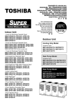
Outdoor unit
Sold Separately Parts
Air outlet (Discharge)
Air inlet
They are provided at front,
rear, left, and right sides.
Power source hole
Wired remote controller
RBC-AMT31E
Hot air is discharged when cooling operation is performed.
Cold air is discharged when heating operation is performed.
CODE No.
SET DATA SETTING TEST
UNIT No.
R.C.
H
No.
TEMP.
FILTER
RESET TEST
ON / OFF
TIMER SET
FAN
MODE
TIME
SWING/FIX
VENT
SET
CL
UNIT
Refrigerant pipe
connecting hole
Fixing leg
Connecting valve is
included inside here.
Indoor unit
Air outlet/Air outlet flap
2-way discharge/3-way discharge
Select air blow direction in cooling or
heating operation each.
2-way discharge or 3-way discharge can be
selected according to the shape or
arrangement of the room.
For details, consult with the dealer which you
have purchased the air conditioner.
Earth screw
It is included in the electric
parts box.
Air filter
Removes dust and trash.
(Air filter is provided in the air grille.)
Clip
The clip is to open/close the
air inlet grille.
Air inlet grille
Air in the room is sucked from here.
Simple wired remote controller
RBC-AS21E2
[4-way Air Discharge Cassette Type]
MMU-AP0091H, AP0121H, AP0151H, AP0181H, AP0241H,
MMU-AP0271H, AP0301H, AP0361H, AP0481H, AP0561H
Earth screw
Air outlet/Air outlet flap
It is included in the electric
parts box.
Select air blow direction in cooling or
heating operation each.
Air filter
Removes dust and trash.
(Air filter is provided in the air grille.)
Clip
The clip is to open/close the
air inlet grille.
Air inlet grille
Air in the room is sucked from here.
[2-way Air Discharge Cassette Type]
Earth screw
Air outlet/Air outlet flap
It is included in the electric parts box.
Select air blow direction in cooling or
heating operation each.
Center panel
Air inlet
Air filter
Air in the room is
sucked from here.
Removes dust and trash.
(Air filter is provided in the center panel.)
3
Wireless remote controller kit
TCB-AX21E2
RBC-AX22CE2 RBC-AX21U(W)-E2
MMU-AP0071MH, AP0091MH, AP0121MH, AP0151MH, AP0181MH
TEST
SETTING
˚C
Earth screw
Air outlet/Air outlet flap
It is included in the
electric parts box.
Select air blow direction incooling
or heating operation each.
Air inlet grille
Air filter
Air in the room is sucked from here.
Removes dust and trash.
(Air filter is provided in the air inlet grille.)
Weekly timer
RBC-EXW21E2
[1-way Air Discharge Cassette Type]
MMU-AP0071YH to AP0121YH
SuMoTuWeTh Fr Sa
PROGRAM1
ERROR
PROGRAM2
PROGRAM3
WEEKLY TIMER
Button
Air outlet/Air outlet flap
Button to open/close
suction port
Change the direction of the air to be
discharged according to cool/heat mode.
Air filter
Removes dust or trash.
(Provided on the suction port.)
Suction port
Sucks air inside of the room from here.
Earth screw
It is included in the electric parts box.
Air filter
Removes dust or trash.
(Provided on the suction port.)
[Concealed Duct Standard Type]
Air outlet flange
Earth screw
Discharge duct is
connected.
Earth screws are provided
in the electric parts box.
Air filter
Removes dust and trash.
(Air filter is provided in the air inlet grille.)
Air inlet
Air in the room is sucked from here.
[Concealed Duct High Static Pressure Type]
Air outlet
Air inlet
Discharge duct is connected.
Suction duct is connected.
Drain pan
Earth screw
Earth screws are provided
in the electric parts box.
[Slim Duct Type]
Air inlet
Suction duct is connected.
Earth screw
It is included in the electric
parts box.
Air filter
Air outlet
(Air filter is not provided to
some models in the series.)
Discharge duct is
connected.
4
Central remote controller
TCB-SC642TLE2
MMU-AP0152SH, AP0182SH, AP0242SH
ZONE
ALL
ZONE
GROUP
CODE
No.
1234
SET DATA
SETTING
R.C.
UNIT No.
TEST
No.
GROUP
SELECT
ZONE
CL
SET
[Under Ceiling Type]
Button
Air inlet port
Button to open/close the suction port
The air in the room is sucked in from this
port.
Earth screw
Air filter
Removes dust or trash.
(Provided on the suction port.)
[High Wall Type]
MMK-AP0071H to AP0241H
Earth screws are provided in the electric
parts box.
Air outlet/Air outlet flap
Change the direction of the air to be discharged according to cool/heat mode.
Earth screw
Earth screws are provided in the electric
parts box.
Air inlet grille
Air in the room is sucked from here.
Air filter
Air outlet/Air outlet flap
Removes dust and trash.
(Air filter is provided in the air inlet grille.)
Change the direction of the air to be
discharged according to cool/heat mode.
MMK-AP0072H to AP0122H
Air inlet grille
Air outlet/Air outlet flap
Air in the room is sucked from here.
Change the direction of the air to be
discharged according to cool/heat mode.
Air filter
Earth screw
Removes dust and trash.
(Air filter is provided in the air inlet grille.)
Earth screws are provided in the electric
parts box.
[Floor Standing Cabinet Type]
Air outlet/Air outlet flap
Exchanges the air direction according to
cooling or heating time.
Earth screw
It is prepared in the electric parts box.
Air filter
Removes dirt or dust.
(It is included in the suction port.)
Air inlet port
Sucks air inside of the room from here.
[Floor Standing Concealed Type]
Air outlet port
Earth screw
It is prepared in the electric parts box.
Drain pan (With drain filter)
This accessory is installed at the local site.
Air inlet port
Sucks air inside of the room from here.
Air filter
Front panel (Lower side)
Removes dirt or dust.
(It is included in the suction port.)
[Floor Standing Type]
Fixing metal holder
Horizontal flap/Air outlet port
Vertical flap
Exchanges the air direction according
to cooling or heating time.
The air can be automatically discharged
rightward/leftward at stated periods.
Air inlet port
Sucks air inside of the room from here.
Drain pan
Water accumulated in the drain pan is
drained from here through the drain pipe.
Air filter
Removes dirt or dust.
Fixing metal holder (Right and left)
Earth screw
It is prepared in the electric parts box.
5
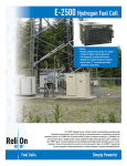
PARTS NAME OF REMOTE CONTROLLER
Display section
CODE No.
In the display example, all indicators are displayed for the explanation.
In reality only, the selected contents are displayed.
• When turning on the leak breaker for the first time, [SET DATA] flashes on
the display part of the remote controller. While this display is flashing, the
model is being automatically confirmed. After the [SET DATA] display has
disappeared, you may use the remote controller.
SET DATA SETTING TEST
Display
section
UNIT No.
R.C.
H
No.
TEMP.
FILTER
RESET TEST
ON / OFF
TIMER SET
FAN
MODE
TIME
SWING/FIX
VENT
SET
CL
Operation
section
UNIT
78 9
2
3
4
5
6
15
1
1
SET DATA SETTING TEST
H
SET DATA display
R.C.
12
4
5
6
13
14
15
” is displayed, clean the air
16
Flap position display
(for 4-Way Air Discharge Cassette Type and
Under Ceiling Type model only)
17
Displays flap position.
9
SWING display
ON / OFF
MODE
,
,
/
buttons. The change
will not be accepted.
(The contents available to be set up on the remote
controller differ according to the central control
mode. For details, refer to Owner’s Manual of the
central control remote controller.)
Set up temperature display
The selected set up temp. is displayed.
11
Central control display
Displayed when using the remote controller together with a central control remote controller.
If the Remote controller is prohibited at the central
flashes when operating the
control side,
Displayed during the up/down movement of the
flap.
10
Mode select control display
Displayed when pushing the “Operation mode
” button while the operation mode is
select
fixed in heating or cooling mode by the system
manager of the air conditioner.
Displayed during a test run.
8
Air volume select display
The selected air volume mode is displayed.
(HIGH)
(AUTO)
(MED.)
(LOW)
In the Concealed Duct High Static Pressure type
models, [HIGH] only is displayed for the air speed.
Filter display
TEST run display
No function display
Displayed if there is no function even when the
button is pushed.
Timer setting setup display
When pushing the Timer setting button, the
display on the timer is selected in order of
→
[OFF] repeat OFF timer
[OFF]
→ No display.
→ [ON]
Operation ready display
Displayed when cooling or heating operation is
impossible because the outdoor temperature goes
out of the operable range.
Timer time display
If “FILTER
filter.
7
While this indication is displayed, the indoor fan
will stop or will go into LOW mode.
CHECK display
Time on the timer is displayed.
(When a fault/error occurs, the check code is
displayed.)
PRE-HEAT display
(for Heat-pump model only)
Displayed when the heating operation starts or a
defrost operation is carried out.
Operation mode select display
Displayed while the protective device works
or a fault/error occurs.
16
11
13
12 14
No.
The selected operation mode is displayed.
3
10
UNIT No.
Displayed during the setup of the timer.
2
17
CODE No.
Remote controller sensor display
Displayed while the sensor on the remote
controller is used.
6
Operation section
Push each button to select a desired operation.
This remote controller can operate a maximum of 8 indoor units.
• Before the unit can begin operation, it is firstly necessary to set the units operating parameters. After this
has been completed the air conditioner can be used by pushing the ON / OFF button only.
1 7
TEMP.
10
2
5
FILTER
RESET TEST
ON / OFF
TIMER SET
FAN
MODE
TIME
SWING/FIX
VENT
SET
CL
8
9
4
6
UNIT
3
1
2
3
4
5
Timer set button
The TIMER SET button is used when the timer
is set up.
8
Operation lamp
The light will be ON when the unit is in operation and OFF when the unit is not being used.
Note) The light will flash if a protective device
has been operated or if the timer function has
an error.
ON / OFF
button
When the button is pushed, the operation
starts. If the button is pressed again, the unit
operation will stop.
When the unit operation has stopped, the
operation lamp and all of the displays will
disappear.
Check button
The CHECK button is used to check the units
operation. During normal operation, do not use
this button.
VENT
Fan
button
VENT
The
button is used when a fan which is
sold on the market is connected.
is displayed on the remote controller
• If
when pushing the VENT button, a fan is not
connected.
9
10
Filter reset button
Resets (Erases) the “FILTER
6
7
Air volume select button
Selects the desired air volume mode.
For the Concealed Duct High Static Pressure
type models this function is unavailable.
” display.
Operation select button
Selects the desired operation mode.
Set up temperature button
Adjusts the room temperature.
Set the desired set temperature by pushing
or
buttons.
the
Air flow direction and Swing function
UNIT
:
OPTION :
If there are multiple indoor units that are controlled by a single remote controller, simply
select each unit in turn for which you wish to
adjust the air flow direction.
SWING/FIX
Remote controller sensor
In normal installations the temperature of the room
is sensed by a temperature sensor on the indoor
unit. However it is possible to have the sensor
within your remote controller. For further details
please contact your local dealer.
• In cases where one remote controller controls the
multiple indoor units, the setup operation is
unavailable in group control.
:
Set up the auto swing and the angle of the flap.
• This function is not provided on the Concealed
Duct Standard Type, High Static Pressure
Type, Floor standing Cabinet Type, Floor
Standing Concealed Type, or Slim Duct Type.
7
CORRECT USAGE
When you use the air conditioner for the first time or when you change the SET DATA value, follow the procedure shown below. For consequent uses the display on the remote controller can be turned on by pushing the
ON / OFF
button only.
Preparation
Turn on the main power supply and/or the leakage breaker.
• When the power supply is turned on, a partition line is shown on the display part of the remote controller.
Note) When the power supply is turned on, the remote controller will not accept any operational inputs until
approximately 1 minute has passed. This is not a failure of the unit.
REQUIREMENT
ON / OFF
• While using the air conditioner, only operate it with the
button. Do not turn it off with the main
power switch or the leakage breaker.
• Do not turn off the leakage breaker while the air conditioner is in use.
• Turn on the leakage breaker 12 hours or more before the air conditioner is to begin operation or if the
system has not been in use for long periods of time.
TEMP.
ON / OFF
4
FILTER
RESET TEST
1
2
3
TIMER SET
FAN
MODE
TIME
SWING/FIX
VENT
SET
CL
3
1
2
UNIT
Cooling only model
ON / OFF
Push the
button.
The operation lamp goes on, and the operation will start.
DRY
COOL
FAN
MODE
Select an operation mode with the
button.
One push of the button, and the display
changes in the order shown on the right.
• “DRY mode” function is not provided on the
Concealed Duct High Static Pressure Type.
Heat-pump model
HEAT
DRY
COOL
FAN
(Dehumidity)
Select the air volume with the FAN button.
AUTO
HIGH
MED.
LOW
One push of the button, and the display
changes in the order shown on the right.
”, the air volume will differ according to the room temperature.
• When the air volume is set to “AUTO
” symbol will be displayed and the air volume will be LOW.
• In DRY mode, the “AUTO
• In heating operation, if the room temperature is not heated sufficiently with the air volume set at “LOW
” operation, select the “MED.
” or “HIGH
” operation.
• The temperature sensor for the indoor unit is located near to the air inlet opening and therefore will differ
slightly from the actual room temperature. This difference may be increased/decreased depending on the
type of room and its design. (Automatic air speed cannot be selected in FAN mode.)
• The Air Volume function is not provided on the “Concealed Duct High Static Pressure Type” instead the
” symbol is displayed.
air speed “HIGH
4
Determine the set up temperature by pushing the “TEMP.
Stop
Push the
ON / OFF
button.
The operation lamp goes off and the unit will stop.
8
” or “TEMP.
” button.
REQUIREMENT
[In Cooling operation]
• The operation will start after approximately 1 minute.
[In Heating operation (For Heat-pump model only)]
• In heating operation, the fan operation may continue for approximately 30 seconds after the air conditioner has stopped.
• The indoor fan will continue the preheat operation for 3 to 5 minutes under stop conditions. The indoor
unit will then begin to blow out hot air.
symbol on the remote controller display will come on.)
(
• When the temperature of the room has reached the setup temperature and the outdoor unit stops, the air
speed reduces and so the air volume will decrease.
mode, if the room temperature reaches the set temperature, the outdoor unit will stop and
• In HEAT
the air flow / volume will decrease.
is displayed.
• In the defrost mode, the fan will stop so that cool air is not discharged and the PRE-DEF
ADJUSTMENT OF WIND DIRECTION
To increase the cooling or heating effect, be sure to use the discharge flap in different directions when in cooling or heating operation.
The characteristics of air are such that cold air will accumulate in the lower half of the room, while hot air will
accumulate in the upper half.
CAUTION
Set the flap horizontally in cooling operation.
If a cooling operation is performed with a downwards discharge, the surface of the discharge port or flap
will become wet with dew, and water may drip down.
REQUIREMENT
• If a heating operation is performed with a horizontal discharge, unevenness the room temperature may
not be equal i.e. there may be a large variance between one side of the room with the other.
4-way Air Discharge Cassette Type
• When the air conditioner is not in operation, the
discharge flap will automatically directs downwards.
• When the air conditioner is in ready status for heating, the discharge flap will be directed upwards.
The swinging operation will begin after heating
ready status has been cleared. Please note the
” symbol will still be displayed on the
“SWING
remote controller even when the unit status is ready
to begin the heating operation.
[In Cooling operation]
Use the discharge flap with a horizontal set point.
[In Heating operation (For Heat-pump model only)]
Use the discharge flap with a downwards set point.
9
How to set up the air direction
Push SWING/FIX button.
1
Every pushing the button, the air direction changes.
In Heating operation
Set the air outlet flap downward.
If directing it upward, the hot air may not come to the foot.
Initial setup
In Cooling / Dry operation
Set the air outlet flap Upwards.
If directing it downwards, the dew may form on the near side of the air discharge
port and could drip.
How to adjust the the air flow direction,
using the swinging function
2
Initial setup
TEMP.
Push the SWING/FIX button.
Set the direction of the air outlet flap to
the lowest position and then push the
SWING/FIX
button again.
• [SWING
] is displayed and the air flow
direction will automatically change either
upwards/downwards.
In the case where one remote controller controls multiple indoor units, each indoor unit can
be selected and its air flow direction can be
adjusted.
FILTER
RESET TEST
ON / OFF
TIMER SET
FAN
MODE
TIME
SWING/FIX
VENT
SET
CL
UNIT
1, 2, 3
4
In FAN operation
In all modes
How to stop the flap from swinging
3
4
Push the SWING/FIX button again while the
horizontal flap is moving.
• The horizontal flap can be stopped at any
position desired. If you wish to return the flap to
it original upwards position, press the SWING/FIX
button again.
* During the cooling/drying operation the horizontal flap will not stop at its most downwards
facing position 9 (reduce the risk of water
dripping), but will instead move to the 3rd
position from the top (as shown in the figure).
Series of
operation
Initial setup
Display when stopping the swing
Fan/Heat
operation
Cool/Dry
operation
UNIT
• To set up the air flow direction individually,
UNIT
button to display each indoor
push the
unit No. in a group control. You can then set the
air flow direction for the displayed indoor unit.
• If there is no display, all the indoor units can be
operated collectively.
UNIT
button, the display
• For every push of the
will alter between units as shown in the figure.
No display
Unit No. 1-1
Unit No. 1-4
10
Unit No. 1-2
Unit No. 1-3
Based on the shape or arrangement of the room, the cold air and hot air can be discharged in two directions or
three directions. For details, please contact your local dealer.
INFORMATION
• If cooling operation is performed with a downwards discharge, dew may form on the surface of the
cabinet or the horizontal flap resulting in dripping.
• If heating operation is performed with a horizontal discharge, the room temperature may not be equal i.e.
there may be a large variance between one side of the room with the other.
• Do not move the horizontal flap directly with your hands; otherwise a fault maybe caused. Select the
direction of the horizontal flap using the flap operation switch on the remote controller. The horizontal flap
will not stop immediately, even if the switch is pushed.
Note) Pushing the switch again when the required louver direction has been reached will stop the louver.
2-way Air Discharge Cassette Type
[In Cooling operation]
Use the air outlet flap with a horizontal set point.
[In Heating operation (For Heat-pump model only)]
Use the air outlet flap with a downwards set point.
Setup of air flow direction and swinging function
1
2
3
SWING/FIX
Push the
button during operation.
• [SWING
] is displayed and the air flow direction will automatically change either upwards/downwards.
In the case of one remote controller that controls multiple indoor units, each indoor unit can be selected
and its air flow direction can be adjusted.
TEMP.
SWING/FIX
Push the
button again during the swinging
of the air outlet flap.
• The air outlet flap will be stopped at the desired position.
UNIT
• To set up the air flow direction individually, push the
UNIT
button to display each indoor unit No. in a group
control. You can then set the air flow direction for the
displayed indoor unit.
• If there is no display, all the indoor units can be operated collectively.
UNIT
button, the display alters
• For every push of the
between units, as shown in the figure.
FILTER
RESET TEST
ON / OFF
TIMER SET
FAN
MODE
TIME
SWING/FIX
VENT
SET
CL
1, 2
No display
Adjustment of air flow direction upwards/downwards
[In Cooling operation]
In cooling operation, use the air outlet flap with a horizontal set point
so that the cold air diffuses the whole room.
[In Heating operation (For Heat-pump model only)]
In heating operation, use the air outlet flap with a downwards set
point so that the hot air is directed towards the floor.
Adjustment of air flow direction rightwards/leftwards
To change the discharge direction to right or left side, set the vertical grille inside of the air outlet flap to the desired direction.
Setup the air flow direction and swinging function
Refer to the description of the “2-way Air Discharge Cassette Type”.
11
3
Unit No. 1-1
Unit No. 1-4
1-way Air Discharge Cassette Type
UNIT
Unit No. 1-2
Unit No. 1-3
Under Ceiling Type
• While the air conditioner is not in operation, the horizontal flap (Up/Down air direction
adjustment plate) will automatically point upwards.
• When the air conditioner is in ready status for heating, the horizontal flap (Up/Down air
direction adjustment plate) will points upwards. The swinging operation will begin after the
” symbol will still be
heating ready status has been cleared. Please note the “SWING
displayed on the remote controller even when the status is ready to heat.
How to adjust the air flow direction
Push the
SWING/FIX
1
button during operation.
Every time you push the button the air
flow direction will change.
In Heating operation
In Cooling / Dry operation
Set the horizontal flap (Up/Down
air direction adjustment plate)
downwards. If the air flow is directed
upwards, the hot air may not reach
the floor, creating an uneven
temperature within the room.
Set the horizontal flap (Up/Down
air direction adjustment plate)
upwards. If directing the air flow
downwards, condensation may
form on the surface of the louver
and may cause water to drip.
Initial setup
How to adjust the air flow direction, using
the swinging function
2
TEMP.
4
ON / OFF
SWING/FIX
Push the
button.
Set the direction of the horizontal flap (Up/
Down air direction adjustment plate) to its
lowest position and then push the SWING/FIX
button again.
• [SWING
] is displayed and the air direction will
automatically upwards or downwards.
In cases where one remote controller controls
multiple indoor units, it is possible to set each
indoor unit individually, so that the air flow direction can be altered.
FILTER
RESET TEST
TIMER SET
FAN
MODE
TIME
SWING/FIX
VENT
SET
CL
1, 2, 3
In FAN operation
How to stop the louver from swinging
3
Initial setup
UNIT
4
In all modes
SWING/FIX
Push the
button again while the horizontal flap is moving
• The horizontal flap can be stopped at any position
desired. If you wish to return the louvre to it original
upwards position, press the SWING/FIX button again.
* During the cooling/drying operation the horizontal flap will not stop at its most downwards
facing position 9 (reduce the risk of water
dripping), but will instead move to the 3rd
position from the top (as shown in the figure).
Series of
operation
Initial setup
Display when stopping the swing
Fan/Heat
operation
UNIT
• To set up the air flow direction individually, push
UNIT
button to display each indoor unit No. in
the
a group control. You can then set the air flow
direction for the displayed indoor unit.
• If there is no display, all the indoor units can be
operated collectively.
UNIT
button, the display
• For every push of the
will alter between units as shown in the figure.
No display
Unit No. 1-1
Unit No. 1-4
Unit No. 1-2
Unit No. 1-3
12
Cool/Dry
operation
Right/Left air direction adjustment
To change the air outlet direction to the right or left side, set the vertical flap located behind the horizontal flap
to the desired direction.
INFORMATION
• If cooling operation is performed with a downwards discharge,
dew may form on surface of the cabinet or the horizontal flap
resulting in possible dripping.
• If heating operation is performed with a horizontal discharge,
the room temperature may not be equal i.e. there may be a
large variance between one side of the room with the other.
High Wall Type
Adjustment of air flow direction upwards/downwards
[In Cooling operation]
In cooling operation, use the horizontal flap with a horizontal set point
so that the cold air diffuses the whole room.
[In Heating operation (For Heat-pump model only)]
In heating operation, use the horizontal flap with a downwards set
point so that the hot air blows towards the floor.
REQUIREMENT
• If cooling operation is performed with the louver set at a downwards position, dew may form on the surface of the cabinet or
the horizontal flap resulting in possible dripping.
• If heating operation is performed with the louver set in a horizontal position, the room temperature may not be equal i.e.
there may be a large variance between one side of the room
with the other.
• Do not move the horizontal flap directly with your hands; otherwise a fault/error may be caused. Select the direction of the
SWING/FIX
button on the remote controller.
horizontal flap using the
The horizontal flap will not stop immediately even if the switch
is pushed.
Note) Pushing the switch again when the required louver direction has been reached will stop the louver.
Adjustment of air flow direction rightwards/leftwards
To change the air outlet direction to the right or left side, set the vertical
flap located behind the horizontal flap to the desired direction.
Setup of air direction and swinging
1H series: Refer to the description of “2-way Air Discharge Cassette
Type”.
2H series: Refer to the description of “Under Ceiling Type, 1-way Air
Discharge Cassette Type (2SH Series)”.
13
Floor Standing Cabinet Type
[In Cooling operation]
In cooling operation, set the air outlet flap with a horizontal
set point so that the cold air diffuses the whole room.
[In Heating operation (For Heat-pump model only)]
In heating operation, set the air outlet flap with a downwards
set point so that the hot air blows towards the floor.
How to change the air outlet port
Change the air outlet port using the following procedure.
1
2
3
4
5
Remove the two fixing screws on the air outlet
port. (The fixing screws are reused.)
Remove the discharge port, by pushing up on
the rear side, to a point where you can remove it
from the rear clip.
Lift the air outlet port upwards and remove it.
Reverse the air outlet port and attach it to the
main unit.
Pay attention so that four claw hooks (two at rear and two
at the lower sides) are hooked on the mounting position.
Be sure to tighten the air outlet port with the
removed fixing screws so that the air outlet port
does not come off.
14
Floor Standing Type
Adjustment of air flow direction upwards/downwards
[In Cooling operation]
In cooling operation, move the flap with your hands so that the horizontal
air outlet points in a direction so that the cold air diffuses the entire room.
[In Heating operation (For Heat-pump model only)]
In heating operation, move the flap with your hands so that the horizontal
air outlet points in a downward direction, towards the floor.
Adjustment of air flow direction rightwards/leftwards
[In case of using unsymmetrical air directions]
Lift up the vertical flap lightly and direct it towards the desired
direction. Once completed lower the flap back down.
In this case, do not use the Swing function.
2
1
[In case of automatic swing]
1
2
3
In this case, do not use the
swing function.
SWING/FIX
Push the
button during operation.
• [SWING
] is displayed and the air direction will automatically change rightwards/
leftwards.
In cases where one remote controller controls multiple indoor units, it is possible to
set each indoor unit individually, so that the
air flow direction can be altered.
TEMP.
ON / OFF
TIMER SET
FAN
MODE
TIME
SWING/FIX
VENT
SWING/FIX
Push the
button again while the
vertical flap is moving will allow you to
stop the louver in the desired position.
FILTER
RESET TEST
SET
CL
UNIT
UNIT
Swing button
• To set up the air flow direction individually,
UNIT
button to display each indoor
push the
unit No. in a group control. Then set up the
air flow direction to the desired indoor unit.
• If there is no display, all the indoor units can
be operated collectively.
UNIT
button, will change
• Every push of the
the display as shown in the figure.
1, 2
No display
3
Unit No. 1-1
Unit No. 1-4
Unit No. 1-2
Unit No. 1-3
INFORMATION
• If cooling operation is performed with downward air outlet, dew may form on the surface of the cabinet or
the horizontal flap, resulting in possible dripping of water.
• If heating operation is performed with the horizontal air outlet actively moving, unevenness of the temperature may increase in the room.
• Do not move the flap directly with your hands during swing operation; otherwise a fault may be caused.
SWING/FIX
button is pushed. To adjust the stop posiThe vertical flap does not stop immediately even if the
SWING/FIX
button.
tion, push the
15
TIMER OPERATION
A type of timer operation can be selected from the following three types.
OFF timer
: The operation stops when the time on the timer has reached the set time.
Repeat OFF timer : The unit will stop, every time the set time period has elapsed.
ON timer
: The unit will start when the time on the timer has reached the set time.
Timer operation
TEMP.
1
FILTER
RESET TEST
ON / OFF
TIMER SET
FAN
MODE
TIME
SWING/FIX
VENT
SET
CL
2
UNIT
34
1
Push the TIMER SET button.
• The timer display (type) changes for every
push of the button.
• SET DATA and timer time displays flash.
OFF
OFF
ON
(OFF timer)
(Repeat OFF timer)
(ON timer)
No display
2
Push the
TIME
buttons to select the “SET TIME”.
For every push of the
button, the set time increases in the unit of 0.5 hr (30 minutes).
The maximum set time is 72.0 hr.
button, the set time decreases in the unit of 0.5 hr (30 minutes).
For every push of the
The minimum set time is 0.5 hr.
3
Push the SET button.
•
display disappears and timer time display goes on.
When the ON timer is activated, the chosen time period will be displayed. Once the time has been
reached, all displays except the ON light will disappear.
SETTING
Cancel of timer operation
4
Push the CL button.
• TIMER display will disappear.
NOTICE
• When the unit stops after the timer reached the preset time, the Repeat OFF timer will resume the
operation. However by pushing the ON / OFF button the repeat function will stop once the time on the
timer has again reached its set time.
16
INSTALLATION
Installation location
WARNING
• Select a location for installation that will be able to safely support the weight of the unit.
If the installation location is not strong enough to support the unit and the unit falls, injury could result.
CAUTION
• Do not install the unit in a location where combustible gases could conceivably leak.
Leaking gases that accumulate in the vicinity of the unit could be ignited by the unit.
REQUIREMENT
• A location that permits the level installation of the unit
• A location that provides enough space to service the unit safely
• A location where water draining from the unit will not pose a problem
Avoid the following types of locations :
• Locations where salt is present in large amounts (seaside areas), or where sulfuric gases are present in
large amounts (hot springs areas)
(If the unit is to be used in such areas, special maintenance is necessary.)
• Locations that generate oils (including machine oils), steam, oily smoke, or corrosive gases
• Locations where organic solvents are used
• Locations in the vicinity of equipment that generates high frequency signals
• Locations where the outdoor unit will blow in the direction of a neighbor's window
• Locations where the noise of the outdoor unit will pose a problem
• Locations with poor air circulation
Electric wiring
WARNING
Ensure that the unit is correctly earthed.
Grounding is necessary. If earthing is incomplete, an electric shock may be caused.
CAUTION
Check that the circuit breaker is fitted.
Attaching a earth leakage breaker is necessary. Otherwise, an electric shock may be caused.
Make sure that the correct capacity fuses are used.
Using wire or copper wire may cause a fire or unit fault.
Ensure that the power supply to the unit is exclusive and is the correct rated voltage.
To disconnect the appliance from the main power supply.
This appliance must be connected to the main power supply by means a circuit breaker or a switch with a
contact separation of at least 3mm.
17
MAINTENANCE
Cleaning of air filter
• When [FILTER] is displayed on the remote controller, it is time to check and if necessary clean the filter.
• Clogging of air filter decreases the cooling/heating effect.
CODE No.
SET DATA SETTING TEST
UNIT No.
FILTER display
R.C.
H
No.
Notifies the time to clean the air filter.
TEMP.
FILTER reset
FILTER
RESET TEST
ON / OFF
TIMER SET
FAN
MODE
TIME
SWING/FIX
VENT
SET
CL
UNIT
Push the FILTER switch after cleaning.
“FILTER” display disappears.
WARNING
Be sure to turn off the main power supply prior to any maintenance.
• Please do not intend to do the daily maintenance and/or Air Filter cleaning by yourself.
Cleaning the air filter and other parts of the unit involves dangerous work in high places, so be sure to
have a qualified service person do it. Do not attempt it by yourself.
Daily maintenance
• For daily maintenance including Air Filter cleaning, please use qualified service personnel, particularly for the
following models 4-way Air Discharge Cassette Type
Concealed Duct Standard Type
Under Ceiling Type
2-way Air Discharge Cassette Type
Slim Duct Type
1-way Air Discharge Cassette Type
Concealed Duct High Static Pressure Type
NO GOOD
NO GOOD
NO GOOD
2-way Air Discharge
Cassette Type
4-way Air Discharge
Cassette Type
NO GOOD
NO GOOD
NO GOOD
Concealed Duct
Standard Type
1-way Air Discharge
Cassette Type
NO GOOD
Under Ceiling Type
Slim Duct Type
18
Concealed Duct
High Static Pressure Type
High Wall Type
(Model : 1H series)
• Push the projection at the center of the air filter.
• Undo the clip on the air filter, pull the air filter downwards while
pushing it towards the main unit side.
Push the air filter,
and pull it downward.
(Model : 2H series)
• Open the air inlet grille.
Lift the air inlet grille up to the horizontal position.
• Take hold of the left and right handles of the air filter and lift it up
slightly, then pull downwards to take it out from the filter holder.
Filter holder
Floor Standing Cabinet Type
• Gently push down on the upper part of the suction port, and then
pull towards you to remove it.
• Take out the air filter inside of the suction port.
Floor Standing Concealed Type
• Push down hook of the air filter on the front panel (Lower side).
• Pull the air filter towards you to remove it.
Front panel
(Lower)
Air filter knob
Floor Standing Type
Removal / Attachment of air filter
• Pull the air filter towards you.
• To attach the air filter, insert it into the main body and push it in.
NOTE
• When cleaning the air filter, use a small brush or cleaning device. If the air
filter is heavily stained, use a neutral detergent mixed with warm water.
• After washing the filter, rinse it out thoroughly and place in the shade to
dry. Do not expose to direct sun light.
• Once the air filter has dried, place the air filter back into the unit.
19
Re-installing the air filter
• Insert the the air filter back into the unit, ensuring that both sides of the filter are positioned correctly inside
of the plastic frame.
• Close the air inlet grille.
If the FILTER lamp on the indoor unit is displayed, press the FILTER button on the remote controller or the
TEMPORARY button on the indoor unit. This will turn the light off.
Filter holder
Cleaning the air inlet grille
1. Remove the air inlet grille.
Hold the two sides of the air inlet grille and open upwards.
Move the center arm to the left and remove the grille.
2. Wash the grille with water using a soft sponge or towel.
(Do not use metallic scrubbing brush or other hard brushes.)
• Use of such hard objects will cause scratches on the
surface of the grille, and the metal coating to peel off.
• If very dirty, clean the air inlet grille with a neutral detergent
for kitchen use, and rinse off with water.
3. Dry the inlet grille, ensuring no water is left.
4. Fit the left and right arms of the air inlet grille to the shafts on
the two sides of the air conditioner and push in completely.
Then push in the center arm.
5. Check that the center arm has been completely inserted and
then close the air inlet grille.
• Push the arrow locations (four) at the bottom of the air inlet
grille to check whether the grill is completely closed.
Cleaning of the main unit / remote controller
CAUTION
• Wipe them with a soft and dry cloth.
• A cloth dampened with cold water may be used on the indoor
unit if it is very dirty.
• Never use a damp cloth on the main unit and the remote
controller.
• Do not use or leave a chemically treated duster on the unit for
long periods of time, as it may damage or alter the colour of the
unit surface.
• Do not use benzine, thinner, polishing powder, or similar solvents for cleaning. These may cause the plastic surface to
crack or deform.
20
Thinner
Polishing Benzene
powder
Chemical
floor-cloth
Do not use.
If you do not plan to use the unit for more than 1 month
1. Operate the fan for 3 to 4 hours to dry the inside of the unit
• Operate “FAN” mode.
2. Stop the air conditioner and turn off the main power supply
or the circuit breaker.
I will wipe soft
and dry cloth!
Checks before operation
1. Check that the air filters are installed.
2. Check that the air outlet or inlet is not blocked.
3. Turn on the main power switch or the circuit breaker for the
main power supply to the air conditioner.
Use after drying
when it has not been
used for a long time!
NOTE
For Air conditioning system which is operated regularly, cleaning and maintenance of the indoor/outdoor
units are strongly recommended.
As a general rule, if an indoor unit is operated for about 8 hours daily, the indoor/outdoor units will need to
be cleaned at least once every 3 months. This cleaning and maintenance shall be carried out by a qualified person.
Failure to clean the indoor/outdoor units regularly will result in poor performance, icing, water leakage and
even compressor failure.
HINTS FOR ECONOMICAL OPERATION
Maintain room temperature at comfortable level
Clean air filters
The clogged air filter impairs the performance of the air conditioner.
Gee, chilly
Never open doors and windows more than what is necessary
Control
To keep the cool or warm air in the room, never open doors and
windows more than what is necessary.
Window curtains
In cooling, close the curtains to avoid direct sunlight.
In heating, close the curtains to keep the heat in.
Clean, please.
Ensure uniform circulation of room air
Ple
ase
clo
se
Adjust the air flow direction so that the air
is evenly circulated throughout the room.
Blows upward
Air flow adjustment
Cool and
dry air
Warm
air
Blows downward
21
AIR CONDITIONER OPERATIONS AND PERFORMANCE
Check before operation
• Check whether earth wire is disconnected or out of place.
• Check that air filter is installed to the indoor unit.
Heating capacity (for Heat-pump model only)
WARNING
Turn on the power supply
12 hours or more before
starting the air conditioner.
• During heating operation the heat pump system operates by
absorbing the heat from the outside air and discharging it into the room.
Therefore if the outside temperature drops, the units heating capacity will decrease.
• When temperature of the outside air is low, it is recommended that you use other forms of heating in conjunction with the air conditioner.
Defrost operation during heating operation (for Heat-pump model only)
• If the outdoor unit has a build up of frost during the heating operation, the operation mode changes automatically to defrost mode to increase the heating effect (for approximately 2 to 10 minutes).
• During defrost operation, fans of the indoor and the outdoor units will stop.
Protection for 3 minutes
• The outdoor unit will not operate for approximately 3 minutes after the air conditioner has been immediately
restarted after being stop, or the power supply has been turned on. This is to protect the system.
Main power failure
• If a power failure occurs during operation, all operations stop.
• When restarting the unit, push the ON/OFF button again.
Fan rotation of stopped unit
• When other indoor units within the same system are in operation, the fan on the indoor units that are on
“stand-by” will rotate to protect the machine once approximately 1 hour for several minutes.
Protective device (High pressure switch)
The high pressure switch operates the unit automatically when excessive load is applied to the air conditioner.
If the protective device operates, the operation lamp will stay but the operation will stop.
When the protective device operates, check characters “ ” on the remote controller display.
The protective device may operate in the following cases.
In Cooling operation
• When suction or discharge port of the outdoor unit is closed.
• When strong winds blow continuously against the discharge port of the outdoor unit.
In Heating operation (For Heat-pump model only)
• When excessive dirt or dust is adhered to the air filter of the indoor unit.
• When the discharge port of the indoor unit is blocked.
Cooling/heating operation of MiNi-SMMS air conditioner
In MiNi-SMMS air conditioner, each indoor unit can be individually controlled. However, cooling operation and
heating operation cannot be performed concurrently for the indoor units, which are connected to the same
outdoor unit.
When cooling operation and heating operation are performed concurrently, the indoor unit which is performing
cooling operation stops, and the “ ” on the unit display will be lit. The indoor unit that is in heating mode will
continue operation.
If the manager has fixed the setting to COOL or HEAT, no other operation can be performed.
When another operation other than the set up one is performed, the “ ” light is displayed on the display part
of the indoor unit.
Characteristics of heating operation (For Heat-pump model only)
• Hot air will not be blown out immediately from the indoor unit. It will take between 3 to 5 minutes (depending
on temperature conditions of the room and the outside) before the indoor heat exchanger warms up sufficiently, to allow hot air to be blown.
• During operation, the outdoor unit may stop if the outside temperature becomes to high.
• When other indoor units are in heating operation, the fan operation of the indoor unit on fan only operation
may be stopped temporarily to prevent hot air from being blown out.
22
The slot provided at side surface of the outdoor
unit is an air intake for cooling the electrical parts.
If the air intake would be clogged, a trouble is
caused on the electrical parts.
Therefore never close the air intake or do not
place any obstacle near the air intake.
Slot for air intake
Air conditioner operating conditions
For the specified performance, operate the air conditioner under the following temperature conditions:
Cooling operation
Outdoor temperature : –5°C to 43°C (Dry-bulb temp.)
Room temperature
CAUTION
Heating operation
: 21°C to 32°C (Dry-bulb temp.), 15°C to 24°C (Wet-bulb temp.)
Room relative humidity – less than 80 %. If the air conditioner operates
in excess of this figure, the surface of the air conditioner may cause dewing.
Outdoor temperature : –15°C to 15.5°C (Wet-bulb temp.)
Room temperature
: 15°C to 28°C (Dry-bulb temp.)
If air conditioner is used outside of the above conditions the units, safety protection devices may operate.
RE-INSTALLATION
DANGER
If the unit position is to be changed and re-located to a new position ask your local dealer or installation specialist. Do not attempt to move the air conditioner yourself, as incorrect installation may
cause electric shock or fire.
Do not install the air conditioner in the following places
• Do not install the air conditioner in any place within 1 m from a TV, stereo, or radio set. If the unit is installed
in such places, noise transmitted from the air conditioner may effect the operation of these appliances.
• Do not install the air conditioner near a high frequency appliance (sewing machine or massager for business
use, etc.), as the air conditioner may malfunction.
• Do not install the air conditioner in a humid or oily place, or in a place where steam, soot, or corrosive gas
may be generated.
• Do not install the air conditioner in a salty place such as a seaside area.
• Do not install the air conditioner in a place where a great deal of machine oil is used.
• Do not install the air conditioner in a place where it is usually exposed to strong winds such as in a seaside
area or on the roof / upper floor of a building.
• Do not install the air conditioner in a place where sulfureous gas may be generated such as in a spa.
• Do not install the air conditioner in a vessel or mobile crane.
Be careful with noise or vibrations
• Do not install the air conditioner in a place where the noise or the hot air created by the outdoor unit will
come into contact with your neighbours.
• Install the air conditioner on a solid and stable foundation as this will reduce the transmission of noise and
vibration that is produced from the outdoor unit.
• If one indoor unit is operating, some sound may be audible from other indoor units that are connected within
the same system (even when not in operation).
23
WHEN THE FOLLOWING SYMPTOMS ARE FOUND
Check the points described below before contacting your local service repair center.
Symptom
Cause
Outdoor unit
• White misty cold air or
water is blown out.
• Sometimes, the noise
“Pushu !” is heard.
• Fan of the outdoor unit stops automatically and performs defrost
operation.
• Solenoid valve works when defrost operation starts or finishes.
Indoor unit
• “Swish” sound is
sometimes heard.
• When the unit is in operation,a sound such as the movement of
water from one area to another may be heard. This sound may
become larger after a period of 2 to 3 minutes once the unit has
begun operation. This is not a cause for concern, but is the movement of the refrigerant or the draining sound of the dehumidifier.
• When the air conditioner system is operating, the stopping indoor
unit in the same system needs temporary flow of refrigerant to
prevent the stay of oil or refrigerant.
Therefore, refrigerant flow sound “shaa/cyu” may be heard, or white
vapor may come out when other indoor unit heating, or cool air
may come out when other indoor unit cooling.
• This sound is generated when the heat exchanger, etc. expands
and contracts slightly due to the change of temperature.
• Various odurs such as those from a carpet, clothes, cigarette, or
cosmetics will adhere to the air conditioner.
• When cooling operation cannot be performed because another
indoor unit performs heating operation.
• When the manager of the air conditioner has fixed the operation to
either COOL or HEAT, but a request or demand contrary to the
setup operation is requested.
• When the fan operation is stopped to prevent the discharge of hot
air.
• Sound is generated when the expansion valve operates when the
power supply has been turned on.
It is not a failure.
• A stopping indoor unit
in the same operating
air conditioner system
emitted sound, white
vapor or cool air.
• Slight “Pishi!” sound is
heard.
• Discharge air smells.
• “
” indication is lit.
Check again.
• When power of the air
conditioner is turned
on, “Ticktock” sound is
heard.
Operates or stops automatically.
• Is the timer “ON” or “OFF”?
Does not operate.
•
•
•
•
•
•
t
Silen
Air is not cooled or warmed sufficiently.
It’s strange.
Is there a power failure to the unit?
Has the power supply been turned off?
Has the power fuse or breaker blown?
Has the protective device operated? (The operation lamp goes on.)
Is the timer “ON”? (The operation lamp goes on.)
Are COOL and HEAT selected simultaneously?
(“ ” indication is lit on the display column of the remote controller.)
•
•
•
•
•
Is the suction port or discharge port of the outdoor unit obstructed?
Are there any doors or windows open?
Is the air filter clogged with dust?
Is the discharge louver of the indoor unit set at appropriate position?
Is the air selection set to “LOW” or “MED” and is the operation
mode set to “FAN”?
• Is the setup temp. the appropriate temperature?
• Are COOL and HEAT selected simultaneously?
(“ ” indication is lit on the display column of the remote controller.)
When the following symptoms are found, stop the operation immediately, turn off the power supply, and contact the dealer from where you have purchased the air conditioner.
• Activation of the power supply causing the unit to operate in an unstable fashion
(power on, power off , power on, power off etc).
• The main power fuse often blows out, or circuit breaker is often activated.
• Foreign matters or water have entered the unit by mistake.
• When the unit fails to operate after the protective device (circuit breaker) has been removed.
Not recommended.
• Other unexplained symptoms or unit abnormalities, that cannot be explained.
24
Confirmation and check
When a error has occurred in the air conditioner, the
check code and the indoor unit No. will appear on
the display part of the remote controller.
The check code is only displayed during while the
unit is operating.
If the display disappears, operate the air conditioner
according to the following “Confirmation of error
history” for confirmation.
CODE No.
UNIT No.
R.C.
Check code
No.
Indoor unit No. in which
an error occurred
Confirmation of error history
When a error has occurred on the air conditioner,
the error history can be confirmed with the following
procedure. (up to 4 errors can be stored in the
memory of the remote controller)
The history can be confirmed from both operating
status and stop status.
TEMP.
2
FILTER
RESET TEST
ON / OFF
TIMER SET
FAN
MODE
TIME
SWING/FIX
VENT
SET
CL
UNIT
1
3
Procedure
Description
SET
TEST
When pushing the
and
buttons at the same time
for 4 seconds or more, the following display will appear.
If [Service check] is displayed, the mode enters into the
error history mode.
1
CODE No.
UNIT No.
• [01 : Order of error history] is displayed in CODE No.
window.
R.C.
No.
• [Check code] is displayed in CHECK window.
• [Indoor unit address in which the error has occurred]
is displayed in UNIT No.
For every push of the [
2
] button, the error history stored in memory is displayed in order.
The numbers in CODE No. indicate CODE No. [01] (latest) → [04] (oldest).
CAUTION
Do not push the
3
,
CL
button because all the error history of the indoor unit will be deleted.
After confirmation, push the
TEST
button to return to the normal display.
1. Check the error codes according to the above procedure.
2. Ask an authorized dealer or qualified service (maintenance) professional to repair or maintain the air conditioner.
3. More details of the service codes are explained in the Service Manual.
25
SICHERHEITSVORKEHRUNGEN
WARNUNG
Warnhinweise zur Installation
Lassen Sie die Installation nur von Ihrem Händler oder einem Fachbetrieb
durchführen.
Zur Installation sind fundierte Fachkenntnisse erforderlich.
Versuchen Sie nicht, das Gerät selbst zu installieren. Wird die Installation nicht
korrekt abgeschlossen, kann es zu Feuer, Stromschlag, Verletzungen oder
Wasserschäden kommen.
Verwenden sie als Zubehörteile nur Teile, die von uns zugelassen sind.
Wenn Sie keine von uns zugelassene Zubehörteile verwenden, kann es zu
Feuer, Stromschlag, Verletzungen oder Wasserschäden kommen. Überlassen Sie
auch die Installation dieser Teile einem ausgebildeten Fachmann.
Wenn Sie Geräte in einem kleinen Raum installieren, treffen Sie
Vorkehrungen, damit bei Kältemittellecks die zulässige Konzentration
nicht überschritten wird.
VORSICHT
Stimmen Sie die Maßnahmen gegen unzulässige Konzentrationen mit Ihrem Händler ab. Sollte die Menge
austretenden Kältemittels den Grenzwert überschreiten, kann es zu Sauerstoffmangel kommen.
Prüfen Sie, ob das Gerät korrekt geerdet ist.
Eine Erdung ist erforderlich. Ist das System nicht geerdet, kann dies zu einem
Stromschlag führen. (Achten Sie auf die regionalen Vorschriften.)
Warnhinweise zur Benutzung
Setzen Sie sich nicht für längere Zeit dem kalten Luftstrom aus und auch
Sie darauf, dass Sie nicht unterkühlen.
Hierdurch kann es zu Gesundheitsschäden kommen.
Stecken Sie keinen Finger oder einen Gegenstand in den Luftauslass.
Da sich der Lüfter mit hoher Geschwindigkeit dreht, kann es zu Verletzungen
kommen.
Kommt es zu einem Fehler (Brandgeruch usw.), schalten Sie das Gerät
und die Stromversorgung aus und nehmen Sie Kontakt mit Ihrem Händler
auf.
Bleibt das Gerät weiter in Betrieb, kann dies zu Feuer, Stromschlägen oder zu
einem Ausfall des Geräts führen.
Warnhinweise zum Umbau/zur Reparatur
Modifizieren Sie nie das Gerät.
Feuer oder ein Stromschlag können die Folge sein.
Lassen Sie Reparaturen durch den Fachhändler bei dem Sie das
Klimagerät erworben haben durchführen.
Wird die Reparatur nicht korrekt abgeschlossen, kann es zu Feuer oder einem
Stromschlag kommen.
Wollen Sie das Gerät an anderer Stelle neu installieren, nehmen Sie mit
Ihrem Händler oder einem Fachbetrieb Kontakt auf.
Wird die Installation nicht korrekt abgeschlossen, kann es zu Feuer, Stromschlag,
Verletzungen oder Wasserschäden kommen.
51
VORSICHT
Vorsichtsmaßnahmen bei der Installation
Prüfen Sie, ob die Ablaufleitungen korrekt installiert sind, damit das
Kondensat ablaufen kann.
Sind die Leitungen nicht korrekt installiert, kann es zu Wasserschäden an Ihren
Möbeln kommen.
Prüfen Sie, ob eine Erdschluss-Sicherung installiert ist.
Stellen Sie sicher, dass am Installationsort des Klimageräts kein
entflammbares Gas entweichen kann.
Strömt Gas aus und sammelt sich an, kann es zu einem Brand kommen.
Prüfen Sie, ob die Außeneinheit fest montiert ist.
Ist dies nicht der Fall, kann sie herunterfallen und einen Unfall verursachen.
Prüfen des Installationsorts
Das Klimagerät darf nicht mit Wasser gereinigt werden.
Ein Stromschlag könnte die Folge sein.
Stellen Sie keine Öfen in den Luftstrom des Klimageräts.
Hierdurch kann es zu einer unvollständigen Verbrennung kommen.
Lüften Sie den Raum regelmäßig, wenn in dem klimatisierten Raum ein
Ofen steht.
Bei ungenügender Lüftung kann es zu einem Sauerstoffmangel kommen.
Prüfen Sie von Zeit zu Zeit den Installationsrahmen usw.
Ist die Befestigung des Geräts beschädigt, kann es herunterfallen und
Verletzungen verursachen.
Stellen Sie keine Pflanzen oder Haustiere in den Luftstrom des
Klimageräts.
Dies kann bei Haustieren zu Krankheiten und bei Pflanzen zu
Wachstumsstörungen kommen.
Verwenden Sie in der Nähe des Klimageräts kein entzündbares Spray
oder sprayen Sie nie direkt auf das Gerät.
Ein Brand kann die Folge sein.
Stellen Sie keine Blumenvase oder einen anderen Behälter mit Wasser
auf das Gerät.
Dringt Wasser in das Gerät ein, kann die Isolierung der Kabel beschädigt werden
und so einen Stromschlag verursachen.
Berühren Sie die Schalter nicht mit nassen Händen.
Ein Stromschlag könnte die Folge sein.
Dieses Klimagerät eignet sich nicht für spezielle Zwecke, weder für die
Konservierung von Lebensmitteln, Präzisionsinstrumenten und
Kunstobjekten noch zur Aufzucht von Tieren, der Zucht von
Topfpflanzen usw.
Schäden können die Folge sein.
52
DEUTSCH
Die Installation einer Erdschluss-Sicherung ist erforderlich. Anderenfalls kann
ein Stromschlag die Folge sein.
BEZEICHNUNGEN DER TEILE
Zubehörteile
Außeneinheit
Luftauslass (Abluft)
Im Kühlbetrieb entweicht warme Luft.
Im Heizbetrieb entweicht kalte Luft.
Lufteinlässe befinden vorn,
hinten rechts und links.
Öffnung für
Stromversorgung
Öffnung für
Kältemittelrohrleitung
Kabelfernbedienung
RBC-AMT31E
Lufteinlass
UNIT No.
R.C.
H
No.
TEMP.
FILTER
RESET TEST
Der Anschluss befindet
sich im Gerät.
Befestigungsfuß
CODE No.
SET DATA SETTING TEST
ON / OFF
TIMER SET
FAN
MODE
TIME
SWING/FIX
VENT
SET
CL
UNIT
Inneneinheit
Luftauslass/Lüftungsklappe
2-Wege/3-Wege-Zuluft
Wählen Sie für den Kühl- oder
Heizbetrieb die jeweilige Luftrichtung.
Entsprechend der Form des Raumes kann
zwischen 2-Wege- und 3-Wege-Zuluft
gewählt werden.
Details erfragen Sie bitte beim dem Fachhändler
bei dem Sie das Klimagerät erworben haben.
Erdungsschraube
Befindet sich im Schaltkasten.
Luftfilter
Filtert Staub und Schmutz
(Luftfilter befindet sich hinter
Lüftungsgitter).
Klammer
Klammer zu Öffnen/Schließen
des Lüftungsgitters.
Abluftgitter
Über das Abluftgitter wird die Raumluft angesaugt.
Einfache Kabelfernbedienung
RBC-AS21E2
[4-Wege-Kassetten-Modell]
MMU-AP0091H, AP0121H, AP0151H, AP0181H, AP0241H,
MMU-AP0271H, AP0301H, AP0361H, AP0481H, AP0561H
Luftauslass/Lüftungsklappe
Befindet sich im Schaltkasten.
Wählen Sie für den Kühl- oder
Heizbetrieb die jeweilige Luftrichtung.
Luftfilter
Filtert Staub und Schmutz
(Luftfilter befindet sich hinter
Lüftungsgitter).
Klammer
Klammer zu Öffnen/Schließen
des Lüftungsgitters.
Abluftgitter
Über das Abluftgitter wird die Raumluft angesaugt.
[2-Wege-Kassetten-Modell]
Erdungsschraube
Luftauslass/Lüftungsklappe
Befindet sich im Schaltkasten.
Wählen Sie für den Kühl- oder
Heizbetrieb die jeweilige Luftrichtung.
Mittenverkleidung
Luftfilter
Lufteinlass
Über das Abluftgitter wird
die Raumluft angesaugt.
Filtert Staub und Schmutz
(Luftfilter befindet sich hinter
Mittenverkleidung).
53
TCB-AX21E2
Erdungsschraube
Infrarot-Fernbedienung
RBC-AX22CE2
RBC-AX21U(W)-E2
MMU-AP0071MH, AP0091MH, AP0121MH, AP0151MH, AP0181MH
TEST
SETTING
˚C
Erdungsschraube
Luftauslass/Lüftungsklappe
Befindet sich im Schaltkasten.
Wählen Sie für den Kühl- oder
Heizbetrieb die jeweilige Luftrichtung.
Abluftgitter
Luftfilter
Über das Abluftgitter wird
die Raumluft angesaugt.
Filtert Staub und Schmutz
(Luftfilter befindet sich hinter Lüftungsgitter).
Wochenzeitschaltuhr
RBC-EXW21E2
[1-Wege-Kassetten-Modell]
MMU-AP0071YH bis AP0121YH
SuMoTuWeTh Fr Sa
PROGRAM1
ERROR
PROGRAM2
PROGRAM3
WEEKLY TIMER
Halter
Luftauslass/Lüftungsklappe
Halter zum
Öffnen/Schließen der
Ansaugöffnung.
Wechseln Sie für Kühl/Heizbetrieb über
die Lüftungsklappen die Zuluftrichtung.
Luftfilter
Filtert Staub und Schmutz
(Luftfilter in Ansaugöffnung)
Luftfilter
Filtert Staub und Schmutz
(Luftfilter in Ansaugöffnung)
Abluftöffnung
Erdungsschraube
Über die Abluftöffnung wird die Raumluft angesaugt.
Befindet sich im Schaltkasten.
[Zwischendecken-Standardmodell]
Luftauslassflansch
Erdungsschraube
Zuluftkanal wird
angeschlossen.
Die Erdungsschraube befindet
sich im Schaltkasten
Luftfilter
Lufteinlass
Filtert Staub und Schmutz
(Luftfilter befindet sich hinter Lüftungsgitter).
Über das Abluftgitter wird
die Raumluft angesaugt.
[Zwischendecken-Luftkanal hohen statischen Druck]
Zuluftöffnung
Lufteinlass
Zuluftkanal wird angeschlossen.
Abluftkanal wird
angeschlossen.
Kondensatschale
Erdungsschraube
Die Erdungsschraube
befindet sich im Schaltkasten
[Flaches Kanalgerät]
Lufteinlass
Erdungsschraube
Abluftkanal wird
angeschlossen.
Befindet sich im Schaltkasten.
Luftfilter
Zuluftöffnung
(Einige Modelle der
Serie sind nicht mit
Luftfiltern ausgestattet.)
Zuluftkanal wird
angeschlossen.
54
Zentrale Fernbedienung
TCB-SC642TLE2
MMU-AP0152SH, AP0182SH, AP0242SH
ZONE
ALL
ZONE
GROUP
CODE
No.
1234
SET DATA
SETTING
R.C.
UNIT No.
TEST
No.
GROUP
SELECT
ZONE
CL
SET
[Abgehängtes Modell]
Halter
Abluftöffnung
Halter zum Öffnen/Schließen der
Ansaugöffnung.
Über die Abluftöffnung wird die Raumluft
angesaugt.
Erdungsschraube
Luftfilter
Die Erdungsschraube befindet sich im
Schaltkasten
Filtert Staub und Schmutz
(Luftfilter in Ansaugöffnung)
Luftauslass/Lüftungsklappe
[Wand modell]
MMK-AP0071H bis AP0241H
Wechseln Sie für Kühl/Heizbetrieb über die Lüftungsklappen die Zuluftrichtung.
Abluftgitter
Erdungsschraube
Über das Abluftgitter wird die
Raumluft angesaugt.
Die Erdungsschraube befindet sich im
Schaltkasten
Luftfilter
Luftauslass/Lüftungsklappe
Filtert Staub und Schmutz
(Luftfilter befindet sich hinter Lüftungsgitter).
Wechseln Sie für Kühl-/Heizbetrieb über
die Lüftungsklappen die Zuluftrichtung.
MMK-AP0072H bis AP0122H
Abluftgitter
Über das Abluftgitter wird die
Raumluft angesaugt.
Luftauslass/Lüftungsklappe
Luftfilter
Erdungsschraube
Wechseln Sie für Kühl/Heizbetrieb über
die Lüftungsklappen die Zuluftrichtung.
Filtert Staub und Schmutz
(Luftfilter befindet sich hinter Lüftungsgitter).
Die Erdungsschraube befindet
sich im Schaltkasten
[Truhenmodell]
Luftauslass/Lüftungsklappe
Je nach Bedarf gekühlte oder erwärmte
Zuluft.
Erdungsschraube
Befindet sich im Schaltkasten.
Luftfilter
Abluftöffnung
Filtert Staub und Schmutz
(Luftfilter in Ansaugöffnung)
Über die Abluftöffnung wird die Raumluft
angesaugt.
[Einbaumodell]
Zuluftöffnung
Erdungsschraube
Befindet sich im Schaltkasten.
Kondensatschale
(mit Kondensatfilter)
Abluftöffnung
Dieses Zubehör wird bauseits montiert.
Über die Abluftöffnung wird die
Raumluft angesaugt.
Luftfilter
Frontverkleidung (Unterteil)
Filtert Staub und Schmutz
(Luftfilter in Ansaugöffnung)
[Standmodell]
Halter zur Befestigung
Horizontale Klappe/Zuluftöffnung
Vertikale Klappe
Je nach Bedarf gekühlte oder erwärmte Zuluft.
Die Zuluftrichtung kann nach rechts oder
nach links ausgerichtet werden.
Erdungsschraube
Befindet sich im Schaltkasten.
Abluftöffnung
Über die Abluftöffnung wird die Raumluft angesaugt.
Kondensatschale
Luftfilter
Das sich in der Kondensatschale
sammelnde Wasser wird über die
Ablaufleitungen abgeleitet.
Filtert Staub und Schmutz
Halter zur Befestigung
(rechts und links)
55
TEILEBEZEICHNUNG DER FERNBEDIENUNG
Anzeige
In der rechten Abbildung werden alle Anzeigen der Fernbedienung dargestellt.
Im Betrieb erscheinen nur die für die gewählte Betriebsart relevanten Anzeigen.
• Wenn Sie das Gerät das erste Mal einschalten, blinkt auf der Fernbedienung
die Anzeige [SET DATA]. Während diese Anzeige blinkt, wird automatisch
ermittelt, welches Modell installiert ist.
Warten Sie daher eine Weile, bis [SET DATA] erlischt, und verwenden Sie
dann erst die Fernsteuerung.
CODE No.
SET DATA SETTING TEST
Anzeige
UNIT No.
R.C.
H
No.
TEMP.
FILTER
RESET TEST
ON / OFF
TIMER SET
FAN
MODE
TIME
SWING/FIX
VENT
SET
CL
Bedienung
UNIT
78 9
2
3
4
5
6
15
1
1
SET DATA SETTING TEST
H
R.C.
12
SET DATA Anzeige
5
Betriebsartanzeige
PRÜF-Anzeige
13
Die Zeit der Zeitschaltuhr wird angezeigt.
(Tritt ein Fehler auf, prüfen Sie den angezeigten
Code.)
14
Anzeige Zeiteinstellung
15
7
” angezeigt, reinigen Sie bitte die
16
Probelauf-Anzeige
Anzeige der Klappenposition
(nur für 4-Wege-Kassettengeräte und
abgehängte Modelle)
17
SCHWENK-Anzeige
gesperrt, blinkt
MODE
wenn die Tasten
ON / OFF
,
,
/
gedrückt werden und die
Änderung wird nicht akzeptiert.
(Die Möglichkeiten, Einstellungen mit der
Fernbedienung vorzunehmen, hängen von der
Betriebsart der zentralen Steuerung ab. Details
finden Sie im Benutzerhandbuch für die zentrale
Steuerung.)
Temperatureinstellung
Hier wird die ausgewählte Temperatur angezeigt.
11
Anzeige der zentralen Steuerung
Wird angezeigt, wenn die Fernbedienung
zusammen mit einer zentralen Steuerung
verwendet wird etc.
Ist die Fernbedienung über die zentrale Steuerung
Erscheint, wenn die Lamellen auf und ab gefahren
werden.
10
Anzeige des Betriebs-Modus
Wird angezeigt, wenn die Systemverwaltung das
Gerät auf Kühl- oder Heizbetrieb eingestellt hat
” gedrückt wird.
und “Betriebsart-Auswahl
Zeigt die jeweilige Klappenposition an
9
Lüftungsleistungsanzeige
Hier wird angezeigt, mit welcher Leistung das
Gebläse arbeitet.
(HOCH)
(AUTO)
(Mittel)
(NIEDRIG)
Bei Modellen mit Zwischendecken-Luftkanälen für
hohen statischen Druck wird für die
Luftgeschwindigkeit nur [HIGH] angezeigt.
Wird während eines Probelaufs angezeigt.
8
Keine Funktion
Wird angezeigt, wenn selbst nach Drücken der Taste
keine Funktion festgestellt werden kann.
Filteranzeige
Wird “FILTER
Luftfilter.
Betriebsbereitschaftsanzeige
Anzeige wenn Kühl- oder Heizbetrieb aufgrund der
Außentemperaturen nicht möglich ist.
Zeitschaltuhr
Wenn Sie die Taste Zeiteinstellung drücken, ändert
sich die Anzeige der Zeitschaltuhr in folgender
→
Reihenfolge AUS [OFF]
→ AN [ON]
→
AUS [OFF] Schaltzeit
Keine Anzeige.
6
VORHEIZEN
(nur bei Modellen mit integrierter Heizung)]
Wird angezeigt, wenn die Heizung startet oder ein
Abtauvorgang stattfindet.
Bei dieser Anzeige stoppt der Ventilator der
Raumeinheit oder das Gerät schaltet in den Modus
NIEDRIG.
Wird angezeigt, wenn die Schutzeinrichtung arbeitet
oder ein Fehler auftritt.
4
16
11
13
12 14
No.
Hier wird die ausgewählte Betriebsart angezeigt.
3
10
UNIT No.
Wird, während Sie eine Zeitvorgabe einrichten,
angezeigt.
2
17
CODE No.
IR-Sensor
Wird angezeigt, während die Fernbedienung
benutzt wird.
56
Bedienung
Drücken Sie eine Taste, um eine gewünschte Funktion auszuwählen.
Mit dieser Fernbedienung können maximal 8 Inneneinheiten gesteuert werden.
• Die gewünschte Betriebsart muss nur einmal eingerichtet werden.
ON / OFF
Danach kann das Klimagerät durch Drücken auf
in der eingestellten Betriebsart gestartet werden.
1 7
TEMP.
10
2
5
FILTER
RESET TEST
ON / OFF
TIMER SET
FAN
MODE
TIME
SWING/FIX
VENT
SET
CL
UNIT
8
9
4
6
3
1
2
3
4
5
6
7
Auswahl der Lüftungsleistung
Wählen Sie mit dieser Taste die gewünschte
Lüftungsleistung.
Modelle mit Zwischendecke-Kanälen für hohen
statischen Druck können nicht bedient werden.
Zeitschaltuhr
Drücken Sie diese Taste, um die Zeitschaltuhr
einzurichten.
8
Prüf-Taste
Die CHECK - Taste dient ausschließlich dazu,
Prüffunktionen auszuführen. Benutzen Sie diese
Taste nicht während des normalen Betriebs.
9
VENT
Ventilator (
)
Diese Taste kann verwendet werden, wenn ein
VENT
marktüblicher Ventilator (
) angeschlossen
ist.
• Wird nach dem Drücken der Taste
angezeigt,
VENT
) angeschlossen.
ist kein Ventilator (
Filter zurücksetzen
Mit dieser Taste löschen Sie die “FILTER
Anzeige
Betriebsanzeige
Diese Kontrollanzeige leuchtet während des
Betriebs. Sie erlischt, wenn das Gerät
angeschaltet wird.
Sie blinkt, wenn die Schutzvorrichtung in Betrieb
ist oder ein Fehler auftritt.
ON / OFF
Taste
Wird diese Taste gedrückt, startet das Gerät.
Drücken Sie sie nochmals, schaltet das Gerät ab.
Danach erlöschen die Betriebsanzeige und alle
Anzeigen der Fernbedienung.
Betriebsart-Auswahl
Wählt die gewünschte Betriebsart.
10
Temperatureinstellung
Stellt die Raumtemperatur ein.
Wählen Sie die Vorgabetemperatur, indem Sie
auf
oder auf
drücken.
OPTION:
”
Fernsteuerungs-Sensor
Normalerweise ermittelt der Temperaturfühler (TEMP)
des Innengeräts die Temperatur.
Zusätzlich kann auch die Umgebungstemperatur an
der Fernsteuerung gemessen werden.
Wenden Sie sich hierzu an den Fachhändler bei dem
Sie das Klimagerät erworben haben.
• Werden mehrere Inneneinheiten mit einer
Fernbedienung gesteuert, steht die Funktion bei
Gruppensteuerung nicht zur Verfügung.
Luftrichtung und Klappenstellung
UNIT
: Werden mehrere Inneneinheiten über
eine Fernbedienung gesteuert, wählen
Sie die Einheit, deren Luftrichtung
eingestellt werden soll.
SWING/FIX
: Automatische Klappenrichtung und
Klappenwinkel
• Diese Funktion steht bei Modellen mit
Zwischendecken-Kanälen, Modellen mit hohem
statischen Druck, Einbaumodellen nicht zur
Verfügung Truhen- oder Flaches Kanalgerät.
57
RICHTIGE HANDHABUNG
Wenn Sie das Klimagerät zum ersten Mal verwenden, oder wenn Sie die Vorgaben unter SET DATA ändern
wollen, gehen Sie wie folgt vor. Vom nächsten Mal an, arbeitet das Klimagerät in derselben Betriebsart, wenn Sie
ON / OFF
drücken.
die Taste
Vorbereitung
Schalten Sie den Hauptschalter (oder die Sicherung) an.
• Ist dies geschehen, schaltet sich die Anzeige der Fernsteuerung ein.
* Nachdem die Stromversorgung wieder eingeschaltet wurde, akzeptiert die Fernbedienung für ca. 1 Minute keine
Tastenbefehle. Dies ist jedoch kein Fehler.
VORAUSSETZUNGEN
ON / OFF
• Um das Klimagerät zu nutzen, schalten Sie es nur mit Hilfe der Taste
nicht über den
Hauptschalter oder die Sicherung ein und aus.
• Schalten Sie, während das Klimagerät in Betrieb ist, nicht die Erdschluß-Sicherung aus.
• Wurde das Gerät für lange Zeit nicht benutzt, schalten Sie 12 Stunden vor Inbetriebnahme die ErdschlußSicherung ein.
TEMP.
ON / OFF
4
FILTER
RESET TEST
1
Drücken Sie die
ON / OFF
TIMER SET
FAN
MODE
TIME
SWING/FIX
VENT
SET
CL
3
3
4
2
UNIT
- Taste.
Modelle nur Kühlung
Die Betriebsanzeige leuchtet und das Gerät startet.
2
1
MODE
Wählen Sie mit
die gewünschte Betriebsart.
Nach jedem Tastendruck wechselt die Anzeige in der rechts
dargestellten Reihenfolge.
• Die “TROCKNEN”-Funktion steht bei Modellen mit
Zwischendecken-Kanälen für hohen statischen Druck
nicht zur Verfügung.
DRY
COOL
FAN
Modelle mit Heizung
HEAT
DRY
COOL
FAN
Wählen Sie die Lüftungsleistung mit der
(Entfeuchten)
“FAN (Ventilator) FAN ” Taste
Nach jedem Tastendruck wechselt die Anzeige in
der rechts dargestellten Reihenfolge.
AUTO
HIGH
MED.
LOW
”
• Wurde die Lüftungsleistung auf “Auto
eingestellt, ändert sich die Lüftungsleistung
entsprechend der Raumtemperatur.
• Im DRY (Trocken) Modus wird “Auto
” angezeigt und die Lüftungsleistung ist NIEDRIG.
• Wird der Raum im Heizbetrieb in der Stellung “LOW (Niedrig)
” nicht warm genug, wählen Sie “MED
” oder “HIGH (Hoch)
”.
(Mittel)
• Die Temperatur wird über einen Temperaturfühler, der sich in der Nähe des Lufteinlasses befindet,
gemessen. Daher unterscheidet sie sich etwas von der eigentlichen Raumtemperatur. Die Vorgabewerte
sind Kriterium für die Raumtemperatur. (Im FAN-(Lüfter)-Modus kann die automatische Lüftungsleistung
nicht ausgewählt werden.)
• Bei Modellen mit Zwischendecken-Kanälen für hohen statischen Druck steht die Auswahl der
Lüftungsleistung nicht zur Verfügung, auf der Anzeige erscheint nur “HIGH
”.
Wählen Sie die Vorgabetemperatur, indem Sie auf “TEMP.
Stopp
Drücken Sie die
ON / OFF
- Taste.
Die Betriebsanzeige erlischt und das Gerät schaltet ab.
58
” oder auf “TEMP.
” drücken.
VORAUSSETZUNGEN
[Im Kühlbetrieb]
• Der Kühlbetrieb startet nach etwa 1 Minute.
[Im Heizbetrieb (nur bei Modellen mit integrierter Heizung)]
• Nachdem der Heizbetrieb beendet ist, kann der Ventilator noch etwa weitere 30 Sekunde in Betrieb sein.
• Der Lüfter der Inneneinheit stoppt in der Vorheizphase für 3 bis 5 Minuten und bläst danach warme Luft in
den Raum. (Auf der Anzeige der Fernbedienung erscheint
.)
• Wenn die Raumtemperatur den Vorgabewert erreicht hat und die Außeneinheit stoppt, läuft der Lüfter auf
kleinster Stufe und die Lüftungsleistung sinkt erheblich.
• Im HEAT-(Heiz)-Modus
läuft der Lüfter auf kleinster Stufe und die Lüftungsleistung sinkt entsprechend,
wenn die Raumtemperatur den Vorgabewert erreicht und das Außengerät stoppt.
• Während des Abtauvorganges stoppt der Ventilator, damit keine kalte Luft ausströmt und PRE-DEF.
wird
angezeigt.
EINSTELLUNG DES LUFTSTROMS
Um den erwünschten Effekt zu erzielen, stellen Sie die Lüftungsklappen für den Kühl- und Heizbetrieb
entsprechend ein.
Wie Sie wissen, sammelt sich kalte Luft am Boden, während sich warme Luft unter der Raumdecke ansammelt.
VORSICHT
Stellen Sie die Klappen im Kühlbetrieb horizontal ein.
Sind die Klappen beim Kühlen nach unten gerichtet, kann sich auf der Oberfläche Kondenswasser bilden und
heruntertropfen.
VORAUSSETZUNGEN
• Befinden sich die Klappen im Heizbetrieb in horizontaler Position, kann es zu einer ungleichmäßigen
Temperaturverteilung im Raum kommen.
4-Wege-Kassetten-Modell
• Wenn das Klimagerät stoppt, werden die Lüftungsklappen automatisch nach unten ausgerichtet.
• Ist das Gerät bereit zum Heizen, fahren die Klappen nach oben.
Obwohl die Bewegung der Lamellen beginnt, nachdem der Status Heizung bereit erreicht wurde,
(Lamellen einstellen) angezeigt, auch wenn der Heizbetrieb
wird auf der Fernbedienung SWING
den Status “bereit” aufweist.
[Im Kühlbetrieb]
Verwenden Sie die Klappen in horizontaler Einstellung.
[Im Heizbetrieb
(nur bei Modellen mit integrierter Heizung)]
Verwenden Sie die Klappen in vertikaler Einstellung.
59
Einstellen der Zuluftrichtung
Drücken Sie SWING/FIX.
1
Jedesmal, wenn Sie die Taste drücken, ändert sich die Zuluftrichtung.
Im Heizbetrieb
Richten Sie die Lüftungsklappen nach unten aus.
Zeigen die Lamellen nach oben, erreicht die warme Luft nicht den Boden.
Anfangseinstellung
Im Kühl-/Trocknen-Betrieb
Richten Sie die Lüftungsklappen nach oben aus.
Sind sie nach unten gerichtet, kann es passieren, dass Kondenswasser von den
Zuluftöffnungen nach unten tropft.
Anfangseinstellung
Starten des Schwenkvorgangs
2
TEMP.
Drücken Sie SWING/FIX.
Stellen Sie die Lüftungsklappen in die niedrigste
Position und drücken dann noch einmal SWING/FIX.
• Es wird [SWING
] angezeigt und die
Lüftungsrichtung wechselt automatisch nach
oben oder nach unten.
Werden mehrere Inneneinheiten mit einer
Fernbedienung gesteuert, kann jede
Inneneinheit angewählt und ihre Luftrichtung
eingestellt werden.
FILTER
RESET TEST
4
TIMER SET
FAN
MODE
TIME
SWING/FIX
VENT
SET
CL
UNIT
1, 2, 3
Schwenkvorgang stoppen
3
ON / OFF
SWING/FIX
Drücken Sie
noch einmal, während sich
die Klappen bewegen.
• Die Lüftungsklappe kann an der gewünschten
Position angehalten werden. Drücken Sie SWING/FIX
ein weiteres Mal, um die Klappen beginnend
bei der höchsten Position neu einzustellen.
* Werden die Klappen im Kühl-/Trocknen-Betrieb
nach unten gefahren, halten Sie nicht an.
Stoppen Sie die Klappen während sie nach
unten fahren, halten sie von oben gesehen in
der 3. Position an.
4
In allen
Betriebsarten
Im FAN (Ventilator)
-Betrieb
Reihenfolge
der Positionen
Anfangseinstellung
Anzeige, wenn Bewegung stoppt
UNIT
• Um die Zuluftrichtung für einzelne Geräte
einzustellen, drücken Sie in einer
UNIT
, um die Nummer der
Gruppensteuerung
jeweiligen Einheit anzuzeigen. Richten Sie
dann die Richtung für die angezeigte Einheit
ein.
• wird keine Einheit angezeigt, können alle
Inneneinheiten zusammen eingestellt werden.
UNIT
• Jedes Mal, wenn Sie
drücken, wechselt
die Darstellung wie angezeigt.
Fan Heat
(Ventilator/Heiz)
-Betrieb
Keine
Anzeige
Einheit Nr. 1-1
Einheit Nr. 1-4
60
Cool/Dry
(Kühlen/Trocknen)
-Betrieb
Einheit Nr. 1-2
Einheit Nr. 1-3
Abhängig von der Raumbeschaffenheit kann die warme oder kalte Luft in zwei oder drei Richtungen gelenkt
werden. Wenden Sie sich für nähere Informationen hierzu an Ihren Fachhändler.
INFORMATION
• Sind die Klappen im Kühlbetrieb nach unten ausgerichtet, kann sic Kondensat bilden und in den Raum tropfen.
• Befinden sich die Klappen im Heizbetrieb in horizontaler Position, kann es zu einer ungleichmäßigen
Temperaturverteilung im Raum kommen.
• Verstellen Sie die Klappen nicht von Hand, da hierdurch Fehler auftreten können. Ändern Sie die
Klappenstellung nur über die Fernbedienung mit Hilfe der Funktion “Flap Operation (Klappenbedienung)”.
Eine horizontal ausgerichtete Klappe stoppt nicht sofort, wenn die Taste gedrückt wird. Um die StoppPosition einzustellen, drücken Sie die Taste.
2-Wege-Kassetten-Modell
[Im Kühlbetrieb]
Verwenden Sie die Klappen in horizontaler Einstellung.
[Im Heizbetrieb
(nur bei Modellen mit integrierter Heizung)]
Verwenden Sie die Klappen in vertikaler Einstellung.
Einstellen der Lüftungsrichtung und der Schwenkbewegung
1
2
3
SWING/FIX
Drücken Sie im Betrieb
.
Stellen Sie die Lüftungsklappen in die niedrigste Position
und drücken dann noch einmal.
• Es wird [SWING
] angezeigt und die Lüftungsrichtung
wechselt automatisch nach oben oder nach unten.
Werden mehrere Inneneinheiten mit einer Fernbedienung
gesteuert, kann jede Inneneinheit angewählt und ihre
Luftrichtung eingestellt werden.
TEMP.
FILTER
RESET TEST
ON / OFF
TIMER SET
FAN
MODE
TIME
SWING/FIX
VENT
SET
CL
UNIT
SWING/FIX
Drücken Sie
noch einmal, während sich die
Klappen bewegen.
• Die Lüftungsklappe kann an der gewünschten Position
angehalten werden.
1, 2
3
UNIT
Keine
Einheit Nr. 1-1
Einheit Nr. 1-2
• Um die Zuluftrichtung für einzelne Geräte einzustellen,
Anzeige
UNIT
, um die
drücken Sie in einer Gruppensteuerung
Einheit Nr. 1-4
Einheit Nr. 1-3
Nummer der jeweiligen Einheit anzuzeigen. Richten Sie
dann die Richtung für die angezeigte Einheit ein.
• Wird keine Einheit angezeigt, können alle Inneneinheiten zusammen eingestellt werden.
UNIT
• Jedes Mal, wenn Sie
drücken, wechselt die Darstellung wie angezeigt.
1-Wege-Kassetten-Modell (Serie 1H)
Einstellung der Lüftungsrichtung nach oben/nach unten
[Im Kühlbetrieb]
Verwenden Sie im Kühlbetrieb die horizontale Stellung der Lüftungsklappen,
damit sich die kalte Luft gleichmäßig im Raum verteilt.
[Im Heizbetrieb (nur bei Modellen mit integrierter Heizung)]
Richten Sie im Heizbetrieb die Lüftungsklappen nach unten, damit die
warme Luft bis auf den Boden geblasen wird.
Einstellung der Lüftungsrichtung nach rechts/nach links
Um den Luftstrom nach rechts oder links zu lenken, verschieben Sie die
vertikalen Lamellen in die gewünschte Richtung.
Einstellen der Lüftungsrichtung und der Schwenkbewegung
Details finden Sie unter “2-Wege-Kassetten-Modell”.
61
Abgehängtes Modell, 1-Wege-Kassetten-Modell (Serie 2SH)
• Schaltet das Klimagerät ab, zeigen die horizontalen Lamellen (Einstellklappen für die
Luftstromrichtung) automatisch nach oben.
• Ist das Klimagerät bereit für den Heizbetrieb, zeigen die horizontalen Lamellen (Einstellklappen für
die Luftstromrichtung) nach oben. Obwohl die Bewegung der Lamellen beginnt, nachdem der Status
(Lamellen einstellen)
Heizung bereit erreicht wurde, wird auf der Fernbedienung SWING
angezeigt, auch wenn der Heizbetrieb den Status “bereit” aufweist.
Einstellen der Zuluftrichtung
Drücken Sie im Betrieb
1
SWING/FIX
.
Jedesmal, wenn Sie die Taste drücken, ändert sich die Zuluftrichtung.
Im Heizbetrieb
Im Kühl-/Trocknen-Betrieb
Richten Sie die horizontalen Lamellen
(Einstellklappen für die
Luftstromrichtung) nach
unten aus. Zeigen die
Lamellen nach oben,
erreicht die warme Luft
Anfangseinstellung
nicht den Boden.
Richten Sie die horizontalen Lamellen
(Einstellklappen für die Luftstromrichtung) nach
oben aus. Sind sie nach
unten gerichtet, kann es
passieren, dass
Kondenswasser von den
Zuluftöffnungen nach unten tropft.
Anfangseinstellung
Starten des Schwenkvorgangs
2
SWING/FIX
Drücken Sie
.
Stellen Sie die horizontalen Lamellen (Einstellklappen
für die Luftstromrichtung) in die niedrigste Position
SWING/FIX
.
und drücken dann noch einmal
• Es wird [SWING
] angezeigt und die
Lüftungsrichtung wechselt automatisch nach oben oder
nach unten.
Werden mehrere Inneneinheiten mit einer
Fernbedienung gesteuert, kann jede Inneneinheit
angewählt und ihre Luftrichtung eingestellt werden.
Schwenkvorgang stoppen
3
4
SWING/FIX
Drücken Sie
noch einmal, während sich die
Klappen bewegen.
• Die Lüftungsklappe kann an der gewünschten Position
angehalten werden. Drücken Sie SWING/FIX ein weiteres
Mal, um die Klappen beginnend bei der höchsten
Position neu einzustellen.
* Werden die Klappen im Kühl-/Trocknen-Betrieb nach
unten gefahren, halten Sie nicht an.
Stoppen Sie die Klappen während sie nach unten fahren,
halten sie von oben gesehen in der 3. Position an.
FILTER
RESET TEST
TIMER SET
FAN
MODE
TIME
SWING/FIX
VENT
SET
CL
1, 2, 3
Im FAN (Ventilator)
-Betrieb
Anfangseinstellung
UNIT
4
In allen
Betriebsarten
Reihenfolge
der Positionen
Anzeige, wenn Bewegung stoppt
UNIT
• Um die Zuluftrichtung für einzelne Geräte einzustellen,
UNIT
, um die
drücken Sie in einer Gruppensteuerung
Nummer der jeweiligen Einheit anzuzeigen. Richten Sie
dann die Richtung für die angezeigte Einheit ein.
• wird keine Einheit angezeigt, können alle
Inneneinheiten zusammen eingestellt werden.
UNIT
• Jedes Mal, wenn Sie
drücken, wechselt die
Darstellung wie angezeigt.
Keine
Anzeige
Einheit Nr. 1-1
Einheit Nr. 1-4
Einheit Nr. 1-2
Einheit Nr. 1-3
62
Fan Heat
(Ventilator/Heiz)
-Betrieb
Cool/Dry
(Kühlen/Trocknen)
-Betrieb
Einstellung des Luftstroms nach rechts oder links
Um den Luftstrom nach rechts oder links zu lenken, verschieben Sie die vertikalen Lamellen in die gewünschte
Richtung.
INFORMATION
• Sind die Klappen im Kühlbetrieb nach unten ausgerichtet, kann sic
Kondensat bilden und in den Raum tropfen.
• Befinden sich die Klappen im Heizbetrieb in horizontaler Position,
kann es zu einer ungleichmäßigen Temperaturverteilung im Raum
kommen.
Wand modell
Einstellung der Lüftungsrichtung nach oben/nach
unten
[Im Kühlbetrieb]
Verwenden Sie im Kühlbetrieb die horizontale Stellung der
Lüftungsklappen, damit sich die kalte Luft gleichmäßig im Raum
verteilt.
[Im Heizbetrieb (nur bei Modellen mit integrierter
Heizung)]
Richten Sie im Heizbetrieb die Lüftungsklappen nach unten, damit die
warme Luft bis auf den Boden geblasen wird.
INFORMATION
• Sind die Klappen im Kühlbetrieb nach unten ausgerichtet, kann sic
Kondensat bilden und in den Raum tropfen.
• Befinden sich die Klappen im Heizbetrieb in horizontaler Position, kann es zu einer ungleichmäßigen Temperaturverteilung im
Raum kommen.
• Verstellen Sie die Klappen nicht von Hand, da hierdurch Fehler
auftreten können. Ändern Sie die Klappenstellung nur über die
Fernbedienung mit Hilfe der Funktion SWING/FIX .
Eine horizontal ausgerichtete Klappe stoppt nicht sofort, wenn
die Taste gedrückt wird. Um die Stopp-Position einzustellen,
drücken Sie die Taste.
Einstellung der Lüftungsrichtung nach rechts/nach
links
Um den Luftstrom nach rechts oder links zu lenken, verschieben Sie
die
vertikalen Lamellen in die gewünschte Richtung.
Einstellen der Lüftungsrichtung und der
Schwenkbewegung
Serie 1H: Details finden Sie unter “2-Wege-Kassetten-Modell”.
Serie 2H: Details finden Sie unter “Abgehängtes Modell, 1-WegeKassetten-Modell (Serie 2SH)”.
63
Truhenmodell
[Im Kühlbetrieb]
Verwenden Sie im Kühlbetrieb die horizontale Stellung der
Lüftungsklappen,
damit sich die kalte Luft gleichmäßig im Raum verteilt.
[Im Heizbetrieb
(nur bei Modellen mit integrierter Heizung)]
Richten Sie im Heizbetrieb die Lüftungsklappen nach unten,
damit die
warme Luft bis auf den Boden geblasen wird.
Wechsel der Luftauslassöffnung
Gehen Sie hierzu wie folgt vor:
1
2
3
4
5
Entfernen Sie die beiden Befestigungsschrauben der
Luftauslassöffnung. (Verwahren Sie die Schrauben
auf.)
Schieben Sie Ihre Hand in die Öffnung und drücken Sie
leicht nach oben. Lösen Sie die Auslassöffnung von
der Klammer auf der Rückseite.
Heben Sie die Luftauslassöffnung nach oben aus dem
Gerät heraus.
Drehen Sie die Auslassöffnung und setzen Sie sie
wieder ein.
Achten Sie darauf, dass die vier Klammern (auf jeder Seite
zwei hinten und zwei unten) in die Befestigungsposition
einrasten.
Befestigen Sie die Luftauslassöffnung wieder mit den
beiden Schrauben, damit sie sich nicht lösen kann.
64
Standmodell
Einstellung der Lüftungsrichtung nach oben/nach unten
[Im Kühlbetrieb]
Verwenden Sie im Kühlbetrieb die horizontale Stellung der
Lüftungsklappen, damit sich die kalte Lüft gleichmäßig im
Raum verteilt. Stellen Sie die Klappe hierzu von Hand ein.
[Im Heizbetrieb (nur bei Modellen mit integrierter Heizung)]
Richten Sie im Heizbetrieb die Lüftungsklappen nach unten, damit die
warme Luft bis auf den Boden geblasen wird. Stellen Sie die Klappe hierzu von Hand ein.
Einstellung der Lüftungsrichtung nach rechts/nach links
[Bei asymmetrischer Luftrichtung]
Heben Sie die vertikale Klappe leicht an und richten Sie sie
in die gewünschte Richtung aus.
Verwenden Sie in diesem Fall nicht die Swing-Funktion.
[Bei automatischer Einstellung der
Lüftungsklappen]
1
2
3
2
1
Verwenden Sie in diesem
Fall nicht die Swing-Funktion.
SWING/FIX
Drücken Sie im Betrieb
.
Stellen Sie die Lüftungsklappen in die niedrigste
Position und drücken dann noch einmal.
] angezeigt und die
• Es wird [SWING
Lüftungsrichtung wechselt automatisch nach oben
oder nach unten.
Werden mehrere Inneneinheiten mit einer
Fernbedienung gesteuert, kann jede Inneneinheit
angewählt und ihre Luftrichtung eingestellt werden.
SWING/FIX
Drücken Sie
noch einmal, während sich die
Klappen bewegen.
• Die Lüftungsklappe kann an der gewünschten
Position angehalten werden.
TEMP.
FILTER
RESET TEST
ON / OFF
TIMER SET
FAN
MODE
TIME
SWING/FIX
VENT
SET
CL
UNIT
1, 2
UNIT
• Um die Zuluftrichtung für einzelne Geräte
einzustellen, drücken Sie in einer Gruppensteuerung
UNIT
, um die Nummer der jeweiligen Einheit
anzuzeigen. Richten Sie dann die Richtung für die
angezeigte Einheit ein.
• Wird keine Einheit angezeigt, können alle
Inneneinheiten zusammen eingestellt werden.
UNIT
• Jedes Mal, wenn Sie
drücken, wechselt die
Darstellung wie angezeigt.
Keine
Anzeige
3
Einheit Nr. 1-1
Einheit Nr. 1-4
Einheit Nr. 1-2
Einheit Nr. 1-3
INFORMATION
• Sind die Klappen im Kühlbetrieb nach unten ausgerichtet, kann sic Kondensat bilden und in den Raum tropfen.
• Befinden sich die Klappen im Heizbetrieb in horizontaler Position, kann es zu einer ungleichmäßigen
Temperaturverteilung im Raum kommen.
• Verstellen Sie die Klappen im Swing-Betrieb nicht von Hand, da hierdurch Fehler auftreten können.
SWING/FIX
gedrückt wird, nicht sofort.
Die vertikale Klappe stoppt, wenn
Um die Stopp-Position einzustellen, drücken Sie die SWING/FIX .
65
ZEITBETRIEB
Es kann zwischen drei verschiedenen Zeitschaltfunktionen gewählt werden:
ABSCHALTZEIT
: Das System schaltet ab, wenn die eingestellte Zeit erreicht ist.
ABSCHALTZEIT Wiederholung : Jedes Mal, wenn die voreingestellte Zeit erreicht ist, schaltet das Gerät ab.
EINSCHALTZEIT
: Das System schaltet ein, wenn die eingestellte Zeit erreicht ist.
Zeitbetrieb
TEMP.
1
FILTER
RESET TEST
ON / OFF
TIMER SET
FAN
MODE
TIME
SWING/FIX
VENT
SET
CL
2
UNIT
34
1
Drücken Sie die TIMER SET Taste.
• Die Anzeige der Zeitschaltuhr ändert sich jedes Mal, wenn Sie die Taste drücken.
• SET DATA und die Anzeige der Zeitschaltuhr blinken.
OFF
OFF
ON
(Abschaltzeit) (Abschaltwiederholung) (Einschaltzeit)
Keine Anzeige
2
Drücken Sie
TIME
, um die “VORGABEZEIT” einzustellen.
Jedes Mal, wenn Sie
drücken, erhöht sich die Zeit um 0,5 Stunden (30 Minuten).
Die maximale Einstellung beträgt 72 Stunden.
drücken, reduziert sich die Zeit um 0,5 Stunden (30 Minuten).
Jedes Mal, wenn Sie
Die minimale Einstellung beträgt 0,5 Stunden.
3
Drücken Sie die SET Taste.
• SETTING erlischt und die Zeitanzeige schaltet sich ein.
(Wenn die Zeitvorgabe aktiviert ist, wird die aktuelle Zeit angezeigt. ON Timer
erlöschen.)
und andere Anzeigen
Löschen der Zeitvorgabe
4
Drücken Sie CL.
• Die Anzeige Zeitanzeige erlischt.
HINWEIS
• Wenn der Betrieb durch die Zeitschaltuhr angehalten wird, kann er durch die Wiederholfunktion neu
ON / OFF
gestartet werden, indem Sie die taste
drücken.
Das System stoppt dann, wenn die vorgegebene Zeit neu erreicht wird.
66
INSTALLATION
Installationsort
WARNUNG
• Wählen Sie einen Platz, der stabil genug ist, um das Gewicht des Geräts aufzunehmen.
Ist der Platz nicht stabil genug, kann das Gerät fallen und so Verletzungen verursachen.
VORSICHT
• Installieren Sie das Gerät nicht an einem Platz, an dem brennbare Gase ausströmen.
Diese Gase können sich, wenn sie sich ansammeln, durch das Klimagerät entzündet werden.
VORAUSSETZUNGEN
• Ein Platz, an dem das Gerät waagerecht ausgerichtet werden kann.
• Ein Platz, an dem genügend Platz für Wartungsarbeiten ist.
• Ein Platz, an dem aus dem Gerät laufendes Wasser nicht zu Problemen führt.
Vermeiden Sie eine Installation an den folgenden Stellen:
• Stellen, an denen das Gerät mit sehr salzhaltiger Luft (in Strandnähe) oder mit großen Mengen
schwefelhaltiger Dämpfe (heiße Quellen) in Kontakt kommt. (In solchen Fällen ist eine besondere Wartung
des Geräts erforderlich.)
• Stellen, an denen Öl (einschl. Maschinenöl), Dampf, öliger Rauch oder korrosive Dämpfe frei werden.
• Stellen, an denen organische Lösemittel verwendet werden.
• Stellen, in deren Nähe Geräte hochfrequente Signale freisetzen.
• Stellen, an denen die Außeneinheit in Richtung benachbarter Fenster bläst.
• Stellen, an denen das Geräusch der Außeneinheit zu Problemen führt.
• Stellen mit ungenügender Luftzirkulation
Elektrische Verkabelung
WARNUNG
Prüfen Sie, ob das Gerät korrekt geerdet ist.
Eine Erdung ist erforderlich. Ist das System nicht geerdet, kann dies zu einem Stromschlag führen.
VORSICHT
Prüfen Sie, ob eine Sicherung installiert wurde.
Eine Erdschluss-Sicherung muss installiert sein. Anderenfalls kann ein Stromschlag die Folge sein.
Vergewissern Sie sich, dass die Sicherungen die korrekte Leistung haben.
Eine Überbrückung durch Kabel kann zu Bränden oder Fehlfunktionen führen.
Das Klimagerät muss an eine Stromversorgung mit der für das Gerät geltenden Spannung angeschlossen
werden.
Trennung des Geräts von der Stromversorgung
Das Gerät muss über eine Sicherung oder einen Schalter, dessen Anschlüsse einen Mindestabstand von
3mm haben, an die Stromversorgung angeschlossen werden.
67
WARTUNG
Reinigen des Luftfilters
• Wird auf der Fernbedienung [FILTER] angezeigt, reinigen Sie den Luftfilter.
• Ein verstopfter Luftfilter beeinträchtigt die Wirksamkeit der Kühlung/Heizung.
CODE No.
SET DATA SETTING TEST
UNIT No.
FILTER-Anzeige
R.C.
H
No.
Meldet, wenn der Filter gereinigt werden muss.
TEMP.
FILTER zurücksetzen
FILTER
RESET TEST
ON / OFF
TIMER SET
FAN
MODE
TIME
SWING/FIX
VENT
SET
CL
UNIT
Drücken Sie nach der Reinigung die Taste FILTER.
Die Anzeige “FILTER” erlischt.
WARNUNG
Ehe Sie mit der Wartung beginnen, schalten Sie den Hauptschalter aus.
• Planen Sie nicht, die regelmäßige Wartung und / oder Reinigung des Filters alleine
durchzuführen.
Da die Reinigung der Luftfilter und anderer Teile des Luftfilters Arbeiten in gefährlicher Höhe einschließt,
beauftragen Sie einen Servicebetrieb mit den Wartungsarbeiten. Versuchen Sie es nicht selbst.
<Tägliche Wartung>
• Beauftragen Sie für die regelmäßige Wartung einschließlich des Reinigens des Luftfilters, besonders bei den
aufgeführten Geräten, einen Fachbetrieb:
4-Wege-Kassetten-Modell
Zwischendecken-Standardmodell
Abgehängtes Modell
2-Wege-Kassetten-Modell
Flaches Kanalgerät
1-Wege-Kassetten-Modell
Modell mit Zwischendecken-Luftkanal für hohen statischen Druck
FALSCH
FALSCH
FALSCH
2-WegeKassetten-Modell
4-WegeKassetten-Modell
FALSCH
FALSCH
FALSCH
ZwischendeckenStandardmodell
1-WegeKassetten-Modell
FALSCH
Abgehängtes Modell
Flaches Kanalgerät
68
Modell mit
Zwischendecken-Luftkanal für
hohen statischen Druck
Wand modell
(Modell: Serie 1H)
• Drücken Sie in die Mitte des Luftfilters. Die Klammer springt heraus.
• Lösen Sie den Luftfilter und ziehen ihn nach unten, während Sie gegen
das Gerät drücken.
Drücken Sie gegen
den Filter und ziehen
ihn nach unten.
(Modell: Serie 2H)
• Öffnen Sie das Abluftgitter.
Heben Sie das Abluftgitter in horizontale Position.
• Halten Sie den rechten und linken Feststellhebel des Filters und
schieben Sie sie leicht nach oben. Dann ziehen sie den Filter nach
außen vom Filterhalter weg.
Filterhalterungen
Truhenmodell
• Drücken Sie leicht auf das Oberteil der Ansaugöffnung und ziehen es zu
sich hin.
• Nehmen Sie den Filter aus der Ansaugöffnung.
Einbaumodell
• Drücken Sie den Haken zur Befestigung des Luftfilters nach unten (unten
am Gerät).
• Schieben Sie den Filter zu sich hin und entfernen Sie ihn.
Frontverkleidung
(Unterteil)
Standmodell
Luftfilterarretierung
Aus-/Einbau des Luftfilters
• Ziehen Sie den Luftfilter zu sich hin.
• Um den Filter einzubauen, setzen Sie ihn ein und drücken ihn nach
innen.
HINWEIS
• Verwenden Sie zur Reinigung des Filters einen Staubsauger oder eine Bürste.
Verwenden Sie bei starker Verschmutzung lauwarmes Wasser mit einem neutralen
Reinigungsmittel.
• Spülen Sie ihn nach dem Waschen gut aus und trocknen Sie ihn im Schatten.
• Setzen Sie den gereinigten Luftfilter wieder ein.
69
Einbau des Luftfilters
• Setzen Sie den oberen Teil des Luftfilters ein, indem Sie die linke und rechte Kante zur Inneneinheit ausrichten,
bis sie sich in der korrekten Position befinden.
• Schließen Sie das Luftgitter wieder.
Leuchtet die FILTER-Anzeige auf der Inneneinheit, drücken Sie FILTER auf der Fernbedienung oder die TEMPORARY (TEMPORÄR) -Taste der Inneneinheit, um die Anzeige abzuschalten.
Filterhalterungen
Reinigen des Zuluftgitters
1. Ausbauen des Zuluftgitters
Halten Sie beide Seiten des Zuluftgitters und öffnen es nach oben.
Schieben Sie den Hebel nach links und nehmen das Gitter ab.
2. Wischen sie es mit einem weichen in Wasser getränkten Tuch
oder Schwamm ab.
(Verwenden Sie keine Metallbürste oder eine andere harte
Bürste.)
• Solche Bürsten verursachen Kratzer auf der Oberfläche des
Gitters und können die Beschichtung beschädigen.
• Wenn es sehr verschmutzt ist, verwenden Sie einen neutralen
Reiniger und spülen es, nachdem Sie das Zuluftgitter gereinigt
haben, mit Wasser wieder ab.
3. Wischen Sie das Wasser ab und lassen das Zuluftgitter trocknen.
4. Drücken Sie die linke und rechte Aufhängung des Zuluftgitters auf
die Bolzen am Klimagerät und drücken dann das Gitter fest auf.
Danach schieben Sie den Hebel wieder in die ursprüngliche
Position.
5. Vergewissern Sie sich, dass der Hebel eingerastet und das
Zuluftgitter fest verankert ist.
• Drücken Sie auf die vier mit Pfeilen gekennzeichneten
Positionen unten am Zuluftgitter, um sicher zu gehen, dass das
Gitter vollständig geschlossen ist.
Säuberung des Innengeräts und der Fernbedienung
VORSICHT
• Verwenden Sie ein weiches, trockenes Tuch.
• Ist die Raumeinheit stark verschmutzt, kann ein mit kaltem
Wasser angefeuchtetes Tuch verwendet werden.
• Verwenden Sie zur Reinigung der Fernbedienung nie ein
feuchtes Tuch.
• Verwenden Sie kein chemisch behandeltes Wischtuch.
Lassen Sie Reinigungsmittel nie länger auf die Oberfläche
des Geräts einwirken.
Dies kann zu Beschädigungen oder Ausbleichungen
führen.
• Verwenden Sie zum Säubern weder Benzin, noch
Verdünner, Poliermittel oder ähnliche Lösungsmittel.
Sie können die Kunststoffoberfläche beschädigen oder
verformen.
70
Verdünner
Scheuerpulver B e n z i n
Chemisch
behandelte
Reinigungstücher
Nicht verwenden.
Falls Sie das Klimagerät für mindestens einen
Monat nicht benutzen,
1. Schalten Sie den Lüfter etwa 3 bis 4 Stunden ein, um das Innere
des Geräts zu trocknen
• Schalten Sie das Gerät in den FAN-(Lüfter)-Modus.
2. Stoppen Sie danach das Klimagerät und schalten Sie es mit dem
Hauptschalter oder der Sicherung aus.
Verwenden Sie ein
weiches, trockenes Tuch.
Tests vor der Inbetriebnahme
1. Prüfen Sie, ob alle Luftfilter installiert sind.
2. Stellen Sie sicher, dass Zuluft- und Abluftöffnungen nicht verstopft
sind.
3. Schalten Sie den Hauptschalter oder die Sicherung der
Hauptstromversorgung ein, um das Klimagerät mit Strom zu
versorgen.
Erst trocknen,
wenn für längere
Zeit nicht benutzt.
HINWEIS
Setzen Sie das Klimagerät regelmäßig ein, sind Reinigung und Wartung der Außen- und Raumeinheit
unbedingt erforderlich.
Wenn Ihr Klimagerät etwa acht Stunden täglich betrieben wird, müssen die Außen- und Raumeinheit
mindestens einmal in DREI MONATEN gereinigt werden. Reinigung und Wartung sollte durch einen
qualifizierten Techniker erfolgen.
Werden Innen- und Außengerät nicht regelmäßig gereinigt, hat dies eine schwache Kühlleistung, Vereisung,
Kondenswasserbildung und vorzeitiges Versagen des Kompressors zur Folge.
HINWEISE ZUM WIRTSCHAFTLICHEN BETRIEB DES KLIMAGERÄTS
Regelt Sie die Raumtemperatur auf ein angenehmes Niveau.
Säubern Sie die Luftfilter regelmäßig.
Sind die Luftfilter verstopft, reduziert sich die Leistung des Geräts.
Öffnen Sie Türen und Fenster nicht öfter als nötig.
Um die Raumtemperatur konstant zu halten, öffnen Sie Türen und Fenster nicht öfter als nötig.
Fenstervorhänge
Schließen Sie die Vorhänge beim Kühlen, um eine direkte Sonneneinstrahlung zu verhindern.
Schließen Sie die Vorhänge beim Heizen, um den Wärmeverlust zu reduzieren.
Sorgen Sie für eine gleichmäßige Zirkulation der Raumluft
Stellen Sie die Lüftungsgitter so ein, dass die Raumluft gleichmäßig zirkuliert.
ieß
en
Huch, kühl hier!
Bitt
es
chl
Regeln
Bläst nach oben
Einstellung des Luftstroms
Kühle und
trockene
Luft
Warme
Luft
Bläst nach unten
71
Bitte säubern.
FUNKTIONEN UND LEISTUNG DES KLIMAGERÄTS
Tests vor der Inbetriebnahme
• Prüfen Sie, ob das Erdungskabel korrekt angeschlossen ist.
• Prüfen Sie, ob der Luftfilter in der Inneneinheit installiert ist.
Heizbetrieb (nur bei Modellen mit integrierter Heizung)
WARNUNG
Schalten Sie die Stromzufuhr 12 Stunden
vor Inbetriebnahme ein.
• Zur Heizung wird eine Wärmepumpe, die Außenluft ansaugt
und warme Luft in den Raum bläst verwendet.
Sinkt die Temperatur der Außenluft, verringert sich die Heizleistung.
• Bei niedrigen Außentemperaturen ist daher eine zusätzliche Heizquelle zu empfehlen.
Abtauung im Heizbetrieb (nur bei Modellen mit integrierter Heizung)
• Bildet sich während des Heizbetriebs Eis auf dem Wärmetauscher der Außeneinheit, wechselt das System
automatisch in den Abtaumodus (für etwa 2 bis 10 Minuten), um eine konstante Heizleistung zu gewährleisten.
• Während des Abtauens stoppen die Ventilatoren von Innen- und Außeneinheit.
3-Minuten-Schutz
• Die Außeneinheit arbeitet, wenn das Gerät abgeschaltet und sofort neu gestartet wird, erst wieder nach etwa 3
Minuten. Hierdurch wird das System geschützt.
Stromausfall
• Kommt es während des Betriebs zu einem Stromausfall, stoppen alle Geräte.
• Drücken Sie zum Neustart des System die Taste ON/OFF (EIN/AUS).
Lüfterdrehung bei angehaltenen Geräten.
• Ist eine Inneneinheit auf Standby geschaltet und arbeiten die anderen Innengeräte weiter, dreht sich der Lüfter
des angehaltenen Geräts zum Schutz 1-mal pro Stunde für einige Minuten.
Sicherheitseinrichtung (Hochdruckschalter)
Der Hochdruckschalter stoppt das Klimagerät automatisch, wenn es überlastet wird.
Hierbei leuchtet die Betriebsanzeige weiter, das Gerät stoppt jedoch.
Hat sich die Sicherheitseinrichtung eingeschaltet, blinkt auf der Anzeige der Fernbedienung das Zeichen “
Die Sicherheitseinrichtung schaltet sich in den folgenden Fällen ein:
”.
Im Kühlbetrieb
• Wenn Zu- oder Abluftöffnung der Außeneinheit geschlossen sind.
• Wenn für längere Zeit starker Wind gegen die Abluftöffnung der Außeneinheit bläst.
Im Heizbetrieb (nur bei Modellen mit integrierter Heizung)
• Wenn der Filter der Inneneinheit mit Staub oder Schmutz verstopft ist.
• Wenn die Abluftöffnung der Inneneinheit verschlossen ist.
Kühl-/Heizbetrieb bei MiNi-SMMS
Bei MiNi-SMMS kann jede Inneneinheit einzeln gesteuert werden.
Es ist jedoch nicht möglich, dass Inneneinheiten, die an eine Außeneinheit angeschlossen sind, gleichzeitig in
unterschiedlichen Betriebsarten arbeiten.
Soll gleichzeitig ein Kühl- und Heizbetrieb durchgeführt werden, schaltet die Inneneinheit, die kühlt ab, und “ ”
leuchtet auf.
Die Inneneinheit, die sich im Heizbetrieb befindet, arbeitet weiter.
Wurden die Geräte fest auf COLL (Kühlen) oder HEAT (Heizen) eingestellt, kann die jeweils andere Betriebsart
nicht ausgeführt werden.
Soll eine andere als die voreingestellte Betriebsart ausgeführt werden, erscheint “ ” und das Gerät stoppt.
Charakteristik des Heizbetriebs (nur bei Modellen mit integrierter Heizung)
• Nach dem Start der Betriebsart wird nicht sofort warme Luft ausgeblasen. Nach 3 bis 5 Minuten (abhängig von
der Raum- oder Außentemperatur) hat sich der Wärmetauscher der Inneneinheit aufgewärmt und warme Luft
wird ausgeblasen.
• Steigt die Außentemperatur, kann die Außeneinheit während des Betriebs anhalten.
• Befinden sich andere Außengeräte im Heizbetrieb, kann der Lüfter zeitweilig stoppen, damit keine heiße Luft
ausgeblasen wird.
72
Die Schlitze auf der Seite der Außeneinheit dienen als
Lüftungsschlitze zur Kühlung elektrischer Teile.
Wenn diese Schlitze verstopfen, kann es zu Problemen
mit diesen Teilen kommen. Achten Sie darauf, dass die
Schlitze nie verschlossen werden oder der Luftstrom
durch Hindernisse gestört wird.
Lüftungsschlitze
Betriebsbedingungen des Klimageräts
Um eine gute Leistung zu erzielen, betreiben Sie das Klimagerät unter folgenden Temperaturbedingungen:
Kühlbetrieb
Außentemperatur
: –5°C bis 43°C (Trockentemp.)
Raumtemperatur
: 21°C to 32°C (Trockentemp.), 15°C to 24°C (Nasstemp.)
VORSICHT
Heizbetrieb
Relative Luftfeuchtigkeit im Raum weniger als 80 %.
Wird das Klimagerät bei höheren Werten betrieben, kann sich an der
Oberfläche Kondenswasser bilden.
Außentemperatur
: –15°C bis 15.5°C (Nasstemp.)
Raumtemperatur
: 15°C bis 28°C (Trockentemp.)
Wird das Klimagerät außerhalb der oben beschriebenen Betriebsbedingungen gefahren, kann sich der
Sicherheitsschutz einschalten.
NEU-INSTALLATION
GEFAHR
Fragen Sie Ihren Fachhändler oder einen Installationsbetrieb, wenn Sie das Klimagerät neu installieren
oder an einem anderen Platz montieren möchten, und beachten Sie folgende Punkte.
Wurde das Klimagerät von Ihnen nicht fachgerecht installiert, kann dies zu einem Stromschlag führen
oder ein Feuer kann die Folge sein.
Installieren Sie das Klimagerät nicht an folgenden Orten
• Installieren Sie das Gerät nie in einem Abstand von einem Meter von Fernsehern, HiFi-Anlagen oder
Rundfunkempfängern. Wird das Gerät an solchen Stellen installiert, können Störungen, die vom Klimagerät
ausgehen, den Empfang der oben genannten Geräte behindern.
• Installieren Sie das Klimagerät nicht in der Nähe eines Geräts das mit hohen Frequenzen arbeitet (Nähmaschinen,
Massagegeräte usw.), da sonst die Funktion des Klimageräts gestört werden kann.
• Installieren Sie das Klimagerät nicht an einem feuchten oder öligen Ort, oder an Stellen, wo Dampf, Ruß oder
korrosive Gase entstehen.
• Installieren Sie das Klimagerät nicht an einem Ort mit stark salzhaltiger Luft, wie beispielsweise direkt an der Küste.
• Installieren Sie das Klimagerät nicht an einem Ort, an dem große Mengen Maschinenöl verwendet werden.
• Installieren Sie das Klimagerät nicht an einem Ort, an dem es ständig starkem Wind ausgesetzt ist, wie beispielsweise
an der Küste, auf dem Dach oder in einem oberen Stockwerk eines Gebäudes.
• Installieren Sie das Klimagerät nicht an einem Ort, an dem schwefelhaltige Gase austreten, wie beispielsweise in der
Nähe einer Heilquelle.
• Installieren Sie das Klimagerät nicht auf einem Schiff oder einem Mobilkran.
Achten Sie auf Geräusche und Vibrationen
• Installieren Sie das Klimagerät nicht an einem Ort, an dem der Geräuschpegel des Außengeräts oder die aus dem
Luftauslass strömende Warmluft Ihre Nachbarn belästigen.
• Installieren Sie das Klimagerät immer auf einem soliden, stabilen Fundament, damit Betriebsgeräusche und
Vibrationen nicht nach außen übertragen werden.
• Wird nur ein einzelnes Innengerät betrieben, können an anderen Innengeräten, die zu der Zeit nicht in Betrieb sind,
Geräusche hörbar sein.
73
VORGEHENSWEISE BEI FOLGENDEN SYMPTOMEN
Prüfen Sie die folgenden Punkte, ehe Sie sich an den Kundendienst wenden.
Symptom
Ursache
Außeneinheit
• Kalte, neblige Luft oder
Wasser strömen aus.
• Manchmal ist ein Zischen
zu hören.
• Lüfter der Außeneinheit stoppt automatisch und Abtauung
wird durchgeführt.
• Magnetventil arbeitet, wenn die Abtauung beginnt oder
beendet wird.
Inneneinheit
• Manchmal ist ein Zischen
zu hören.
• Bei Betriebsbeginn, während des Betriebs oder direkt nach
Ende des Betriebs kann ein Geräusch wie fließendes Wasser
gehört werden und die Betriebsgeräusche können für 2 bis 3
Minuten nach dem Start ansteigen. Es handelt sich um
Flussgeräusche von Kältemittel oder Kondensat des
Entfeuchters.
• Wenn das Klimasystem arbeitet, fließt durch eine angehaltene
Inneneinheit des Kühlkreises noch Kältemittel, damit sich kein
Öl oder Kältemittel ansammeln kann.
Daher hören Sie evtl. Strömungsgeräusche oder es kann,
wenn andere Inneneinheiten im Heizbetrieb arbeiten, weißer
Dampf oder im Kühlbetrieb kalte Luft entweichen.
• Dieses Geräusch entsteht, wenn sich der Wärmetauscher
aufgrund von Temperaturänderungen leicht ausdehnt oder
zusammenzieht.
• Unterschiedliche Gerüche von Wänden, Teppichen,
Zigaretten, Kleidung oder Kosmetik können Sich im
Klimagerät ansammeln.
• Kühlbetrieb kann nicht durchgeführt werden, weil sich eine
andere Inneneinheit im Heizbetrieb befindet.
• Wenn das Klimagerät fest auf COOL (Kühlen) oder HEAT
(Heizen) eingestellt wurde und eine andere Betriebsart
ausgeführt werden soll.
• Wenn der Lüfter stoppt, damit keine heiße Luft eingeblasen
wird.
• Das Geräusch ertönt, wenn der Strom eingeschaltet ist und
sich das Expansionsventil öffnet.
Dies ist kein Fehler.
• Aus einer abgeschalteten
Inneneinheit des gleichen
Kühlkreises entweichen
Dampf und kalte Luft, oder
Sie hören Geräusche.
• Manchmal ist ein Zischen
zu hören.
• Die Zuluft riecht
• “
” leuchtet
• Wir die Stromzufuhr des
Klimageräts eingeschaltet,
ist ein klicken zu hören.
Startet oder stoppt automatisch
• Ist die Zeitschaltuhr “ON (AN)” oder “OFF (AUS)”?
Arbeitet nicht
•
•
•
•
Nochmals prüfen
h
sc
eräu
G
Kein
Luft ist nicht ausreichend kalt oder warm
Komisch
Ist die Stromversorgung ausgefallen?
Ist der Hauptschalter ausgeschaltet?
Ist die Hauptsicherung durchgebrannt?
Hat sich die Schutzeinrichtung eingeschaltet?
(Die Kontrollleuchte schaltet ein)
• Ist die Zeitschaltuhr “ON (AN)”?
(Die Kontrollleuchte schaltet ein)
• Wurde gleichzeitig COOL (Kühlen) und HEAT (Heizen)
ausgewählt.
”.)
(In der Anzeige der Fernbedienung erscheint “
•
•
•
•
Ist Zu- oder Abluftöffnung der Außeneinheit verschlossen?
Sind Türen oder Fenster geöffnet?
Ist der Luftfilter mit Staub verstopft?
Befindet sich die Lüftungsklappe der Inneneinheit in der
richtigen Stellung?
• Wurde die Lüftungsleistung auf “LOW (Niedrig)” oder “MED
(Mittel)” eingestellt und als Modus “FAN (Lüfter)” gewählt?
• Ist die Temperatureinstellung angemessen?
• Wurde gleichzeitig COOL (Kühlen) und HEAT (Heizen)
ausgewählt?
(In der Anzeige der Fernbedienung erscheint“
”.)
Kommt es zu einem der folgenden Fehler, schalten Sie das Gerät und die Stromversorgung sofort aus und nehmen
Sie Kontakt mit Ihrem Händler auf.
• Die Funktion des Schalters ist nicht in Ordnung.
• Die Sicherung brennt häufig durch oder die Sicherung springt oft heraus.
• Fremdkörper oder Wasser sind in das System eingedrungen
• Obwohl die Ursache für die Aktivierung der Schutzvorrichtung beseitigt wurde, läßt sich das System nicht mehr in
Betrieb nehmen.
• Andere unübliche Probleme.
74
Bestätigung und Prüfung
Tritt ein Fehler auf, erscheint in der Anzeige der
Fernbedienung eine entsprechende Kennziffer und die
Nummer der betroffenen Raumeinheit.
Die Kennziffer wird nur während des Betriebs
angezeigt.
Erlischt die Anzeige, gehen Sie wie in dem Absatz
“Aufruf des Fehlerspeichers” beschrieben vor.
CODE No.
UNIT No.
R.C.
Prüfcode
No.
Nr. der fehlerhaften
Raumeinheit
Aufruf des Fehlerspeichers
TEMP.
Tritt ein Fehler auf, kann der Fehlerspeicher wie im
folgenden beschrieben aufgerufen werden.
(Es können bis zu 4 Fehler gespeichert werden.)
Der Fehlerspeicher kann während des Betriebs oder,
wenn das System angehalten wurde, aufgerufen
werden.
2
FILTER
RESET TEST
ON / OFF
TIMER SET
FAN
MODE
TIME
SWING/FIX
VENT
SET
CL
UNIT
1
3
Vorgehensweise
Beschreibung
SET
TEST
Wenn Sie gleichzeitig
und
für 4 Sekunden oder
länger drücken, erscheint die rechts stehende Anzeige:
1
Wird [Service Check] angezeigt, wechselt die
Fernbedienung in die Fehlertabelle.
CODE No.
UNIT No.
• [01: Reihenfolge der Fehler] wird im Fenster CODE NO.
angezeigt.
R.C.
No.
• [Kennziffer] wird im Fenster [CHECK] angezeigt.
• [Die Nummer der fehlerhaften Raumeinheit] erscheint
unter UNIT NO.
Jedesmal, wenn Sie die Tasten
Speicher.
2
,
drücken, wechseln Sie zum nächsten Fehler im
Die Zahlen unter CODE NO. zeigen den letzten [01] bis zum ältesten [04] Fehler an.
VORSICHT
Drücken Sie nicht die Taste
3
CL
, da Sie dann den Fehlerspeicher löschen.
Um den Fehlerspeicher zu verlassen, drücken Sie auf die Taste
TEST
.
1. Prüfen Sie die Fehler wie oben beschrieben.
2. Zur Reparatur oder Wartung des Klimagerätes wenden Sie sich an einen autorisierten Händler oder einen
qualifizierten Installateur.
3. Details zu den Kennziffern der Fehler finden Sie im Servicehandbuch.
75
TOSHIBA CARRIER CORPORATION
2 CHOME 12-32, KONAN, MINATOKU, TOKYO, 108-0075, JAPAN
EH99924701
9[_b_d]Ioij[ci
:_]_jWb?dl[hj[hIkf[h:_]_jWb?dl[hj[h
7_h#ÔemWd]b[_i
WkjecWj_YWbboi[jjej^[
ceijik_jWXb[i[jj_d]
WYYehZ_d]jeh[gk_h[c[dji
:hW_dfWdfei_j_ed[Z
_di_Z[j^[kd_j[dikh[ij^[
cWn_ckc^o]_[d[WdZ_i
[Wi_boh[YoYbWXb[
H((H*&-Yh[fbWY[c[dj
j[Y^debe]o
?d\hW#h[Zh[Y[_l[hi[dieh
ibejfei_j_ed[ZjeWbbem
Z_h[Yjm_h[b[iiYedjheb
I[b\Yb[Wd_d]
9[_b_d]Ioij[ci
I]ZXZ^a^c\hjheZcYZYjc^ihVgZi]Z^YZVahdaji^dc[dgVeea^XVi^dchl]ZgZXZ^a^c\kd^YhVgZgZhig^XiZYdgcdiVkV^aVWaZ#
I]Zjc^iXVcWZbdjciZYdcidi]ZXZ^a^c\hjg[VXZdghZb^XdcXZVaZYidaZVkZVhaZZ`egdÒaZl^i]bVm^bjbV^g
Y^hig^Wji^dc#
:_]_jWb?dl[hj[h
CeZ[bH[\[h[dY[
?dZeeh
EkjZeeh
H7L#IC+,*9J#;
H7L#IC+,)7J#;
H7L#IC.&*9J#;
H7L#IC.&)7J#;
H7L#IC''&*9J#;
H7L#IC''&)7J#;'
H7L#IC'*&*9J#;
H7L#IC'*&)7J#;'
*#%
,#%
&%#%
&'#(
Cdb^cVa8dda^c\8VeVX^in
`L
Cdb^cVa=ZVi^c\8VeVX^in
`L
*#+
-#%
&&#'
&)#%
J@IdiVa8dda^c\
`L
*#%%
+#,%
&%#%%
&'#(%
J@IdiVa=ZVi^c\
`L
)#,%
+#+*
.#)%
&'#%*
J@HZch^WaZ8dda^c\
`L
)#''
*#-*
,#,(
-#,*
::G$8DE
'#,*$(#)&
'#,,$(#')
'#-*$(#*
'#,'$(#()#*($(#+'
H::G$H8DEKVajZ
)#.,$)#&&
)#,&$(#.%
)#.'$(#*'
?dZeehH[jW_bFh_Y[
,++
--+
.*+
'"'&+
EkjZeehH[jW_bFh_Y[
.)+
'"('+
'"+*&
'",.+
Ioij[cH[jW_bFh_Y[
'"+*(
("&*(
("*)-
(".*(
H7L#IC+,*9J#;
H7L#IF+,*7J#;
H7L#IC.&*9J#;
H7L#IF.&*7J#;
H7L#IC''&*9J#;
H7L#IF''&*7J#;
H7L#IC'*&*9J#;
H7L#IF'*&*7J#;
&'#*
Ikf[h:_]_jWb?dl[hj[h
CeZ[bH[\[h[dY[
?dZeeh
EkjZeeh
Cdb^cVa8dda^c\8VeVX^in
`L
*#%
,#&
&%#%
Cdb^cVa=ZVi^c\8VeVX^in
`L
*#+
-#%
&&#'
&)#%
J@IdiVa8dda^c\
`L
*#%(
,#&'
&%#%+
&'#*,
J@IdiVa=ZVi^c\
`L
)#)+
+#(-
-#.(
&&#&+
J@HZch^WaZ8dda^c\
`L
)#''
*#-*
,#,(
-#,*
::G$8DE
(#'&$(#-
(#'&$(#,%
(#,*$)#',
(#(*$(#-)
H::G$H8DEKVajZ
*#&,$)#&(
*#+($(#.(
*#,($(#.)
*#(+$)#*%
?dZeehH[jW_bFh_Y[
,++
--+
.*+
'"'&+
EkjZeehH[jW_bFh_Y[
'"&'+
'"+'&
'"/&&
("'&&
Ioij[cH[jW_bFh_Y[
'"-((
("))-
("-/-
)"(+-
I]ZhnhiZbeg^XZ^cXajYZhVhiVcYVgYgZbdiZ
XdcigdaaZgG78"6BI(':gZiV^aeg^XZ*'
8dbegZ]Zch^kZa^hid[XdcigdahdceV\Zh.-id&%.
7YY[iieh_[i
:[iYh_fj_ed
7ZZ_j_edWbH[jW_bFh_Y[
G78"6BH)&:
G78"6BH*&:":H
GZbdiZ8dcigdaX$l,9VnI^bZg
A^iZK^h^dcGZbdiZ8dcigdaaZg
'.
+.
)f^EkjZeehCeZ[bDe$
(+
G6K"HE&&%)6I-":
G6K"HE&)%)6I-":
G6K"HE&+%)6I-":
H[jW_bFh_Y[
("(-+
(")+&
("-&&
HZZeV\Z(.[dg
heZX^ÒXVi^dcYViV
J[Y^d_YWbIf[Y_ÓYWj_ed
:_]_jWb?dl[hj[h
?dZeeh
EkjZeeh
H7L#IC+,*9J#;
H7L#IC+,)7J#;
H7L#IC.&*9J#;
H7L#IC.&)7J#;
H7L#IC''&*9J#;
H7L#IC''&)7J#;'
H7L#IC'*&*9J#;
H7L#IC'*&)7J#;'
Cdb^cVa8dda^c\8VeVX^in
`L
*#%
,#%
&%
&'#(
J@8dcY^i^dch"8dda^c\8VeVX^in
`L
*#))
,#,+
&&#+*
&(#*.
J@8dcY^i^dch"HZch^WaZ8dda^c\
`L
)#''
*#-*
,#,(
-#,*
Cdb^cVa=ZVi^c\8VeVX^in
`L
*#+
-
&&#'
&)
J@8dcY^i^dch"=ZVi^c\8VeVX^in
`L
*#'&
,#%-
.#+-
&'#'.
6ccjVaEdlZg8dchjbei^dc
:cZg\nAVWZa8dda$=ZVi
EdlZgHjeeanIdE]VhZ
>ciZgXdccZXi^c\8VWaZ
HnhiZbHiVgi8jggZci
Gjcc^c\8jggZcibVm
`L]
.&%
&'+*
&,**
''+%
7$6
7$6
7$6
9$8
DjiYddg$&
DjiYddg$&
DjiYddg$&
DjiYddg$&
(XdgZ:
?dZeehKd_ji
6^gÓdl=^\]$Adl
6^gÓdl=^\]$Adl
Jc^i9^bZch^dch=mLm9
HdjcYEgZhhjgZ=$A
LZ^\]i
EkjZeehKd_ji
Hj\\ZhiZY;jhZH^oZ
E^eZH^oZh
GZ[g^\ZgVciEgZ"8]Vg\Z$AZc\i]
6YY^i^dcVaGZ[g^\ZgVci
BVmE^eZAZc\i]$=Z^\]i
HdjcYEgZhhjgZ8dda$=ZVi
Jc^i9^bZch^dch=mLm9
LZ^\]i
(XdgZ:
(XdgZ:
(XdgZ:
6
&
&
&
&
6
-#,&&'#*
&'#'(&)#.
&+#'%'&#%
'&#&-'&#'
H7L#IC+,*9J#;
H7L#IC.&*9J#;
H7L#IC''&*9J#;
H7L#IC'*&*9J#;
B($]
,-%$+%%
&&&%$-,+
&+*%$&',%
&-%%$&(-+
a$h
'&,$&+,
(%-$')(
)*-$(*'
*%%$(-*
bb
'&%m.&%m+-%
'&%m&&-%m+-%
'&%m&*.*m+-%
'&%m&*.*m+-%
Y76
(-$(%
(-$((
)&$(*
)($(,
`\
'&
'*
((
((
H7L#IC'*&)7J#;'
H7L#IC+,)7J#;
H7L#IC.&)7J#;
H7L#IC''&)7J#;'
6
&+
&+
&*
'*
bb$^c
b
\$b
b
&'#,&$'Ç"+#)&$)Ç
&*#.*$-Ç".#*($-Ç
&*#.*$-Ç".#*($-Ç
&*#.*$-Ç".#*($-Ç
'%
'%
(%
(%
'%
)%
)%
)%
(%$(%
(%$(%
*%$(%
*%$(%
Y76
)+$)-
)-$*%
*($*)
*)$*)
bb
**%m,-%m'.%
**%m,-%m'.%
,.*m.%%m('%
,.*m.%%m('%
`\
(-
))
,+
,+
H7L#IC+,*9J#;
H7L#IF+,*7J#;
H7L#IC.&*9J#;
H7L#IF.&*7J#;
H7L#IC''&*9J#;
H7L#IF''&*7J#;
H7L#IC'*&*9J#;
H7L#IF'*&*7J#;
Ikf[h:_]_jWb?dl[hj[h
?dZeeh
EkjZeeh
Cdb^cVa8dda^c\8VeVX^in
`L
*#%
,#&
&%
&'#*
J@8dcY^i^dch"8dda^c\8VeVX^in
`L
*#))
,#,+
&&#+*
&(#*.
J@8dcY^i^dch"HZch^WaZ8dda^c\
`L
)#''
*#-*
,#,(
-#,*
Cdb^cVa=ZVi^c\8VeVX^in
`L
*#+
-
&&#'
&)
J@8dcY^i^dch"=ZVi^c\8VeVX^in
`L
*#'&
,#%-
.#+-
&'#'.
6ccjVaEdlZg8dchjbei^dc
:cZg\nAVWZa8dda$=ZVi
EdlZgHjeeanIdE]VhZ
>ciZgXdccZXi^c\8VWaZ
HnhiZbHiVgi8jggZci
Gjcc^c\8jggZcibVm
`L]
,-%
&&%*
&((*
&-+*
6$6
6 $6
6 $6
6$6
DjiYddg$&
DjiYddg$&
DjiYddg$&
DjiYddg$&
(XdgZ:
?dZeehKd_ji
6^gÓdl=^\]$Adl
6^gÓdl=^\]$Adl
Jc^i9^bZch^dch=mLm9
HdjcYEgZhhjgZ=$A
LZ^\]i
EkjZeehKd_ji
Hj\\ZhiZY;jhZH^oZ
E^eZH^oZh
GZ[g^\ZgVciEgZ"8]Vg\Z$AZc\i]
6YY^i^dcVaGZ[g^\ZgVci
BVmE^eZAZc\i]$=Z^\]i
HdjcYEgZhhjgZ8dda$=ZVi
Jc^i9^bZch^dch=mLm9
LZ^\]i
(XdgZ:
(XdgZ:
(XdgZ:
6
&
&
&
&
6
,#')&(#*
&%#(+'%#*
&'#*&'&#(*
&,#(%'&#(*
H7L#IC+,*9J#;
H7L#IC.&*9J#;
H7L#IC''&*9J#;
H7L#IC'*&*9J#;
B($]
,-%$+%%
&&&%$-,+
&+*%$&',%
&-%%$&(-+
a$h
'&,$&+,
(%-$')(
)*-$(*'
*%%$(-*
bb
'&%m.&%m+-%
'&%m&&-%m+-%
'&%m&*.*m+-%
'&%m&*.*m+-%
Y76
(-$(%
(-$((
)&$(*
)($(,
`\
'&
'*
((
((
H7L#IF'*&*7J#;
H7L#IF+,*7J#;
H7L#IF.&*7J#;
H7L#IF''&*7J#;
6
&%
&+
&+
'%
bb$^c
b
\$b
b
&'#,&$'Ç"+#)&$)Ç
&*#.*$-Ç".#*($-Ç
&*#.*$-Ç".#*($-Ç
&*#.*$-Ç".#*($-Ç
'%
(%
(%
(%
'%
)%
)%
)%
*%$(%
*%$(%
,*$(%
,*$(%
Y76
),$)-
)-$).
).$*%
*&$*'
bb
**%m,-%m'.%
-.%m.%%m('%
&()%m.%%m('%
&()%m.%%m('%
`\
))
+(
.(
.(
(,