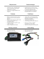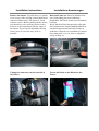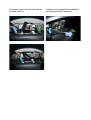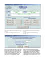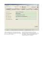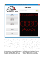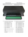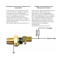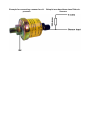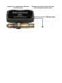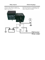
1
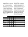
User's Manual
Benutzerhandbuch
(Version 2012-03-21)
Thanks for buying the FIS-Control. Please note
the following safety informations and the legal
disclaimer.
Danke für den Kauf des FIS-Controls. Bitte
beachte unbedingt die folgenden
Sicherheitshinweise und den
Haftungsausschluss.
Safety information
Sicherheitshinweise
The FIS-Control is intended to be installed in a
vehicle. Therefore it is connected to the board
voltage and other electrical devices. The
installation has to be done by an expert. A
mistake may result in short circuits or damages
that potentially can lead to misbehavior of
systems in the vehicle.
Das FIS-Control ist dafür bestimmt, ins
Fahrzeug eingebaut zu werden. Dabei wird es
mit Bordspannung und anderen elektrischen
Geräten verbunden. Der Einbau darf nur durch
Fachleute erfolgen. Ein Fehler bei der
Installation kann zu Kurzschlüssen und
Beschädigungen führen und eventuell ein
Fehlverhalten von Systemen im Fahrzeug nach
sich ziehen.
Lasse dich während der Fahrt nicht von den
Anzeigen des FIS-Controls ablenken. Bediene
es nur, wenn die aktuelle Verkehrssituation es
zulässt.
Das FIS-Control baut über die DiagnoseSchnittstelle Verbindungen zu Steuergeräten im
Fahrzeug auf. Obwohl die Steuergeräte so
ausgelegt sein sollten, dass durch eine aktive
Diagnose-Verbindung kein Fehlverhalten
auftritt, kann dies nicht ausgeschlossen werden.
Also benutze das FIS-Control nicht in riskanten
Situationen und verbinde es nicht mit
sicherheitsrelevanten Steuergeräten, es sei
denn, du weißt was du tust.
Don't let the FIS-Control distract you while
driving.
Operate the FIS-Control only when the traffic
situation allows this.
The FIS-Control will establish diagnosisconnections to ECUs in your car. Although all
ECUs should be built in a way, that this has no
impact to normal operation, it can not be
absolutely certain that there will be no
abnormal behavior or malfunction. So better
don't use the FIS-Control in risky situations
and don't connect it to safety relevant ECUs
unless you know what you are doing.
Legal disclaimer
Haftungsausschluss und
Rechtliches
I assume no responsibility for damages that are
caused by the installation or the use of the FISControl.
Even if properly installed, I don't give a
guaranty that it will function flawlessly under
all circumstances.
In some countries modifications to a car have
to be approved by the authorities. In this case it
can be illegal to install or use the FIS-Control
when driving on public roads.
Ich übernehme keine Haftung für Schäden die
aus dem Einbau oder dem Betrieb des FISControls entstehen.
Selbst bei fachgerechter Installation kann ich
keine Garantie für einen unter allen Umständen
fehlerfreien Betrieb geben.
Eventuell erlischt in deinem Land durch
Modifikationen am Fahrzeug die
Straßenzulassung. In diesem Fall ist die
Teilnahme am öffentlichen Straßenverkehr
nach Einbau des FIS-Control unter Umständen
unzulässig.
Requirements
•
•
Instrument cluster with DIS-display
(Driver Information System) that
supports the 3-wire-bus
ECUs have to support KWP1281 for
diagnosis.
Voraussetzungen
•
•
Features
•
•
•
•
•
Display of all measurement values of
the ECUs in the car (not restricted to
OBD II)
Display of the diagnostic trouble codes
Line graph-display for every
measurement value
Converter "K-Line to UART" (VAGCOM compatible)
Menus in English and German
Funktionen
•
•
•
•
•
Delivery contents
•
•
FIS-Control main unit
Plug'n'play cable harness
Kombiinstrument mit FIS-Anzeige
(Fahrer-Informations-System), das per
3-Leiter-Bus angesteuert wird
Steuergeräte müssen das DiagnoseProtokoll KWP1281 unterstützen
Anzeige aller von den Steuergeräten
angebotenen Messwertblöcken (nicht
beschränkt auf OBD II)
Anzeige der Fehlerspeicher
Linien-Diagramm für jeden Messwert
Konverter „K-Line zu UART“
(kompatibel zu VAG-COM)
Deutsche und Englische Menüsprache
Lieferumfang
•
•
FIS-Control Steuergerät
Plug'n'play Kabelsatz
Installation instructions
Installations-Anweisungen
Remove the cluster. Typically there is a plastic
cover on top of the steering console than can be
removed without tools. The cluster is fixed
with two screws. Before pulling out the cluster,
you should cover the steering console with a
towel to avoid scratching it with the edges of
the cluster. If you have an adjustable steering
wheel, move it out of the way as far as
possible.
Baue den Tacho aus. Dazu ist üblicherweise
eine Verkleidung über dem Lenkstock
abzuhebeln. Der Tacho ist mit zwei Schrauben
befestigt.
Bevor man den Tacho herauszieht, sollte man
den Lenkstock mit einem Handtuch abdecken,
um ihn nicht mit den Kanten des Tachos zu
zerkratzen. Wenn du ein verstellbares Lenkrad
hast, dann stelle es so ein, dass es möglichst
wenig im Weg ist.
Unplug the connectors on the backside of
the cluster.
Trenne die Kabel an der Rückseite des
Tachos.
Extend the original cable harness with the
provided cable set.
Verlängere den Original-Tachokabelbaum
mit dem mitgelieferten Kabelsatz.
Connect the FIS-Control.
The cable set consists of two or three separate
cables. The endings of the cables that lead to
the FIS-Control are marked with different
colors. The sockets on the FIS-Control are
labelled (A, B, C and D).
The mapping is shown in the following table.
The columns represent the colors of the
connectors on the backside of the cluster and
the colors of the cable that go to the FISControl.
Example: for the Audi TT the black end of the
blue cable goes to the socket A of the FISControl. The yellow end of the blue cable is not
needed (don't mix it up with the yellow end of
the green cable). The yellow end of the green
cable goes to the socket B. The cable endings
of the gray cable go to socket C and D. The red
connector is not needed.
Cluster
FIS-Control
Blue connector
Schließe das FIS-Control an.
Der Kabelsatz besteht je nach Fahrzeug aus
zwei oder drei Kabeln. Die Kabelenden, die
zum FIS-Control gehen sind farblich kodiert.
Am FIS-Control sind vier Buchsen (A, B, C
und D) gekennzeichnet.Die Zuordnung kann
der folgenden Tabelle entnommen werden. Die
Spalten stehen für die Farben der Anschlüsse
auf der Tacho-Rückseite, bzw. für die farbliche
Kodierung der Kabelenden, die zum FISControl gehen. Beispiel: beim Audi TT kommt
das schwarz markierte Ende des blauen Kabels
in die Buchse A des FIS-Controls. Das gelbe
Ende des blauen Kabels wird nicht benötigt
(bitte nicht mit dem gelben Ende des grünen
Kabels verwechseln). Das gelbe Ende des
grünen Kabels kommt in Buchse B. Die
Kabelenden des grauen Kabels kommen in
Buchse C und D. Vom roten Anschluss des
Tachos werden keine Kabel benötigt.
Green connector
Gray connector
Red connector
black
yellow
black
yellow
red
black
red
black
red
Audi A3/S3 (1998 - 1999)
A
B
-
-
-
-
-
C
D
Audi A3/S3 (>2000)
A
-
-
B
-
C
D
-
-
Audi A4/S4 (1998 - 1999)
A
B
-
-
-
-
-
C
D
Audi A4/S4/RS4 (>2000)
A
-
-
B
-
C
D
-
-
Audi A6 (<1999)
A
B
-
-
-
-
-
C
D
Audi A6 (>2000)
A
-
-
B
-
C
D
-
-
Audi TT
A
-
-
B
-
C
D
-
-
VW Golf (<2002)
A
B
C
-
-
-
-
-
D
VW Golf (>2002)
A
B
C
-
D
-
-
-
-
VW Passat (<2001)
A
B
C
-
-
-
-
-
D
VW Passat (>2001)
A
B
C
-
D
-
-
-
-
VW T4
A
B
C
-
-
-
-
-
D
VW Sharan (>2000)
A
B
C
-
D
-
-
-
-
Seat Alhambra (>2000)
A
B
C
-
D
-
-
-
-
Skoda Superb
A
B
C
-
D
-
-
-
-
Configuration of the
instrument cluster
In order to have the output of the FIS-Control
displayed on the cluster it may be necessary to
change the software coding of the cluster.
The coding has to be set in a way that the
cluster is aware of a navigation system (as the
FIS-Control emulates such a device) that
outputs data on the cluster screen.
Clusters with CAN-bus support also have to be
configured to accept the data sent via the 3wire-bus and not via CAN-bus.
Konfiguration des
Kombiinstruments
Damit die Ausgabe vom FIS-Control auf dem
Tacho dargestellt werden kann, muss dieser
eventuell umkodiert werden.
Die Kodierung muss so eingestellt werden,
dass der Tacho weiß, dass ein NavigationsSystem (denn als solches verhält sich das FISControl) Daten auf dem Tacho-Display
darstellen will.
Bei Tachos mit CAN-Bus muss zudem
konfiguriert sein, dass die Datenübertragung
vom FIS-Control nicht über den CAN-Bus,
sondern per 3-Leiter-Bus erfolgt.
The coding can either be done at your repair
shop. Or it can be done by yourself with a
laptop and an OBD-dongle.
Das Umkodieren kann entweder von einer
Werkstatt mit einem Diagnosetester erledigt
werden, oder mit Hilfe eines Laptops und eines
OBD-Interfaces auch selbst gemacht werden.
The FIS-Control can be used as OBD-dongle
via its RS-232 interface or via bluetooth. All
you need is a laptop with either one of these
interfaces and the appropriate software tool.
There are two OBD diagonstic tools available
for free download that can be used: VCDS-lite
and WBH-Diag.
Das FIS-Control kann über seine RS-232Schnittstelle und per Bluetooth als OBDInterface benutzt werden. Man benötigt also
nur ein Laptop, das eines der beiden genannten
Schnittstellen bereitstellt und eine
entsprechende Diagnose-Software. Die beiden
Programme VCDS-lite und WBH-Diag sind
kostenlos im Internet verfügbar.
VCDS-lite and WBH-Diag 0.89 can be used
for a wired connection via RS-232. To use a
wireless connection via bluetooth, WBH-Diag
1.00 (and above) is the right tool.
VCDS-lite und WBH-Diag 0.89 sind nur für
eine kabelgebundene Verbindung per RS-232
geeignet. Für die Nutzung über Bluetooth
eignet sich WBH-Diag ab Version 1.00.
To start the FIS-Control in "OBD-interface"mode, keep the Up-key pressed (for RS-232
connection) while turning on the ignition, or
hold the Down-key (for bluetooth).
Um das FIS-Control in den "OBD-Interface"Modus zu versetzen ist beim Einschalten der
Zündung entweder die Hoch-Taste (für
Verbindung via RS-232) oder die Runter-Taste
(für Bluetooth) gedrückt zu halten.
There will be no status screen displayed by the
FIS-Control on the cluster screen. To check if
the FIS-Control actually is in OBD-mode, try
to operate the boardcomputer with the buttons
of the wiper stalk. This shouldn't be possible in
this case.
Es wird keine Statusanzeige vom FIS-Control
auf dem Tacho-Display erfolgen. Ein Zeichen
dafür, dass sich das FIS-Control tatsächlich im
OBD-Modus befindet ist, dass der
Bordcomputer nun nicht mehr über die Tasten
des Lenkstockhebels bedienbar ist.
Soft coding with VCDS-lite
Kodierung mit VCDS-lite
VCDS-lite can be downloaded for free directly
from the developer's website: http://www.rosstech.com/vcds-lite/download/index.html
VCDS-lite kann kostenlos direkt beim
Hersteller Ross-Tech runtergeladen werden:
http://www.ross-tech.com/vcdslite/download/index.html
Only use a battery powered laptop to connect
to the FIS-Control. Use a straight serial cable
and connect to a "real" serial port if possible. If
your laptop doesn't have a serial RS-232 port
anymore, you might try a serial-to-USB
adaptor. But some of them will cause
connection problems or will not work at all. I
have positive experience with devices that are
using the FTDI chipset.
Das Laptop sollte nur im Akkubetrieb mit dem
FIS-Control verbunden werden. Idealerweise
verbindet man das FIS-Control mittles eines
1:1-Kabels mit einer "echten" seriellen
Schnittstelle. Verfügt das Laptop über keinen
seriellen RS-232-Anschluss mehr,
funktionieren prinzipiell auch Seriell-auf-USBAdapter. Allerdings kommt es mit einigen zu
Verbindungsproblemen. Gute Erfahrungen
habe ich mit Geräten mit FTDI-Chipsatz
gemacht.
After starting VCDS-lite you first have to
perform a connection test. Click the button
"Option" on the main screen.
Nach dem ersten Start von VCDS-lite wird
zunächst ein Verbindungstest durchgeführt.
Dazu wählt man im Hauptbildschirm die
Schaltfläche "Options".
On the next screen choose the correct COMport. If the port is unkown or not selectable,
have a look at the Windows device manager.
There you can see the serial ports of your
laptop and change the port assignment.
Im nächsten Bild wählt man den COM-Port der
verwendeten Schnittstelle. Ist der Port nicht
bekannt, oder nicht auswählbar kann man im
Windows Geräte-Manager nachschauen und
dort auch die Zuweisung des Ports ändern.
Click "Test" to verify the connection to the
FIS-Control.
Checklist:
1. Ignition is turned on
2. FIS-Control is in "OBD-interface"-mode
3. cable connection is ok
4. correct COM port is selected
Über die Schaltfläche "Test" kann die
Verbindung zum FIS-Control überprüft werden.
Checkliste:
1. Zündung an
2. FIS-Control im "OBD-Interface"-Modus
3. Kabelverbindung in Ordnung
4. Richtiger COM-Port ausgewählt
If the test finished successfully, click "Save".
VCDS-lite is ready to use now.
Nach erfolgreichem Test klickt man auf "Save".
VCDS-lite ist jetzt einsatzbereit.
To check/change the software coding of your
cluster, click "Select" in the main screen of
VCDS and choose "17-Instruments" in the
control module list.
Um die Kodierung des Tachos zu
prüfen/ändern, wählt man im VCDSHauptmenü "Select" und in der Liste der
Steuergeräte "17-Instruments".
The currect coding is shown in the box "Soft.
Coding".
To change the coding, click "Recode – 07".
Die aktuelle Kodierung steht im Feld "Soft.
Coding".
Um die Kodierung zu ändern wählt man
"Recode – 07".
If the current coding is less than "16000", you
have to add "16000" to the current value. For
example: If "00044" is the currently active
coding, it has to be changed to "16044". You
don't need to change the WorkShop Code.
Click "Do It!" to accept the new coding
Sollte die aktuelle Kodierung kleiner als
"16000" sein, so muss auf den aktuellen Wert
"16000" addiert werden. Beispiel: Ist bisher
"00044" kodiert, so muss dieser auf "16044"
geändert werden. Der WorkShop Code braucht
nicht verändert werden. Mittels "Do It!" wird
settings.
die Kodierung vorgenommen.
For clusters with CAN-bus it might be
necessary to also update the list of active CAN
devices. For Audi this usually is done by
setting the adaptation channel 62 to "0". For
VW you might have to recode the software
coding of the CAN-gateway (control module
19) with the same value that is currently set.
Bei CAN-Bus Tachos ist zusätzlich zur
Kodierung eventuell die sogenannte Verbauliste
anzupassen. Bei vielen Audi ist dazu der
Adaptionskanal 62 auf "0" zu ändern. Bei VW
aktualisiert sich die Verbauliste, indem man das
CAN-Gateway (Steuergerät 19) mit dem
bereits gesetzten Wert neu kodiert.
Soft coding with WBH-Diag
Kodierung mit WBH-Diag
WBH-Diag can be donwloaded for free directly
from the website of the developer Florian
Schäffer:
http://www.blafusel.de/obd/obd2_wbhdiag.htm
l
WBH-Diag kann kostenlos direkt beim
Entwickler Florian Schäffer runtergeladen
werden:
http://www.blafusel.de/obd/obd2_wbhdiag.htm
l
There are two versions available. The older
version 0.89 is (like VCDS-lite) intended for a
wired connection. Therefore the FIS-Control
has to be connected woth a straight serial cable
to the RS-232 port of yur laptop.
Von der Software gibt es zwei Versionen. Die
ältere Version 0.89 ist wie VCDS-lite für eine
kabelgebundene Diagnose gedacht. Das FISControl muss also mit einem seriellen 1:1Kabel mit der RS-232-Schnittstelle des Laptops
verbunden werden.
Die neueren Versionen von WBH-Diag
funktionieren dagegen über Bluetooth.
Die Bedienung beider Versionen ist dabei
weitestgehend identisch.
The newer versions of WBH-Diag can be used
via bluetooth.
Operation of both versions is almost identical.
Hint: In the program folder of WBH-Diag there
is a config file called "wbh-diag.ini". You can
set the language of the software: "Sprache=de"
German) or "Sprache=en" (English). Also it is
possible to define the COM port here. To
disable the advertisment message that pops up
on every program start, set "Splash=nein".
Info: Im Ordner von WBH-Diag befindet sich
die Konfigurationsdatei "wbh-diag.ini". Dort
kann man die Sprache der Software einstellen:
"Sprache=de" oder "Sprache=en". Außerdem
lässt sich der richtige COM-Port voreinstellen.
Auf Wunsch kann man die Werbeeinblendung,
die sonst bei jedem Programmstart erfolgt,
deaktivieren: "Splash=nein".
After starting the tool, select the control unit
"023 (17) – Instruments" and the correct COM
port. Now click "Connect".
Nach dem Start der Software sollte das
Steuergerät "023 (17) Kombiinstrument" sowie
der richtige COM-Port ausgewählt werden.
Nun klickt man auf "Verbinden".
The coding of the cluster can be changed in the
tab "Software Config".
If the current coding is less than "16000", you
have to add "16000" to the current value. For
example: If "00044" is the currently active
coding, it has to be changed to "16044".
Die Kodierung des Tachos wird in der Lasche
"Softwarekonfiguration" geändert.
Sollte die aktuelle Kodierung kleiner als
"16000" sein, so muss auf den aktuellen Wert
"16000" addiert werden. Beispiel: Ist bisher
"00044" kodiert, so muss dieser auf "16044"
geändert werden.
For clusters with CAN-bus it might be
necessary to also update the list of active CAN
devices. For Audi this usually is done by
setting the adaptation channel 62 to "0". For
VW you might have to recode the software
coding of the CAN-gateway (control module
19) with the same value that is currently set.
Bei CAN-Bus Tachos ist zusätzlich zur
Kodierung eventuell die sogenannte Verbauliste
anzupassen. Bei vielen Audi ist dazu der
Adaptionskanal 62 auf "0" zu ändern. Bei VW
aktualisiert sich die Verbauliste, indem man das
CAN-Gateway (Steuergerät 19) mit dem
bereits gesetzten Wert neu kodiert.
When setting the adaptation channel you might
see an error message, telling that the new value
was not accepted by the control module. This
message can be ignored. To check that the
value was accepted, have a look at the current
value. If this is the value you wanted to set, the
coding was successful.
Bei Einstellen des Adaptionskanals kann
fälschlicherweise eine Fehlermeldung
auftauchen, dass der gewünschte Wert nicht
übernommen werden konnte. Dieser Fehler
kann ignoriert werden. Ob der Wert doch
übernommen wurde, lässt sich am "aktuellen
Wert" ablesen. Ist es der gewünschte Wert, hat
die Kodierung doch funktioniert.
Hint: WBH-Diag 0.89 can be used without any
restriction when using the FIS-Control as
OBD-dongle. Via bluetooth only the following
functions are available:
- Control Unit Data
- Software Config
- Channel Adaption
- Measure Blocks
- Error Codes
- Clear error codes
Info: WBH-Diag 0.89 kann über das FISControl in vollem Umfang genutzt werden.
Über Bluetooth stehen nur folgende Funktionen
zur Verfügung:
- Steuergeräte-Infos
- Softwarekonfiguration
- Kanalanpassung
- Meßwerte
- Fehlercodes
- Fehlercodes löschen
Operating the FIS-Control
Bedienung des FIS-Controls
The main menu
Das Hauptmenü
After the ignition is switched
on, the FIS-Control is inactive
at first and the standard boardcomputer is displayed on the
DIS screen. To activate the
FIS-Control, perform a
longpress (about 2 seconds) on
the up-key. Now the main
menu gets visible. You can move the marker
with the up/down-key. To select a menu item,
mark the item and press the set-key.
Nach dem Einschalten der
Zündung befindet sich das
FIS-Control zunächst im
inaktiven Zustand. Es wird
also der gewohnte
Bordcomputer angezeigt.
Aktiviert wird das FIS-Control
durch einen Langdruck (etwa 2
Sekunden) auf die Hoch-Taste. Dadurch
erscheint das Hauptmenü. Nun lässt sich durch
Drücken der Hoch- bzw. Runter-Taste der
gewünschte Menüpunkt markieren und
schließlich mit der Auswahl-Taste aufrufen.
Wird das Hauptmenü verlassen, so ist der
serienmäßige Bordcomputer wieder sichtbar.
After the user quits the main menu, the
standard board-computer is seen again.
The settings menu
Das Einstellungs-Menü
With the menu item “ECU
ADDRESS” the control unit is
selected, that will be connected
when starting a measurement.
The most interesting values
will come from the engine
control unit. It has the number
1. Of course all other control
units are also available. For most (but not all) a
label will be shown. The address “0” has a
special meaning. This will select the sensors
that are connected to the inputs of the FISControl.
Über den Menüpunkt
„STEUERGERÄT“ wird das
Steuergerät ausgewählt, zu
dem eine OBD-Verbindung
hergestellt werden soll. Die
interessantesten Messwerte
liefert sicherlich das
Motorsteuergerät. Es hat die
Nummer 1. Es lassen sich natürlich auch alle
anderen Steuergeräte-Nummern auswählen. Für
die meisten (aber nicht alle) wird die
Bezeichnung angezeigt. Eine besondere
Funktion hat das Steuergerät „0“. Dieses wählt
die Sensoren, die direkt an das FIS-Control
angeschlossen sind.
Die gemachten Einstellungen lassen sich über
„SPEICHERN“ im Speicher des FIS-Controls
ablegen. Sie werden beim nächsten Start
automatisch wieder geladen.
The settings can be stored to the internal
memory of the FIS-Control with “SAVE
SETTINGS”. They are loaded automatically
on each startup.
Reading the measurement blocks
After the setup is done, the
reading can be started. The
FIS-Control will connect to the
chosen ECU and show one
measurement block.
In the first line of the display
the current ECU-number and the currently
selected block are indicated.
Each measurement block consists of up to four
separate values.
The values are refreshed between 2 and 5 times
per second. The actual speed depends on the
ECU and the number of transmitted values in
the current measurement block.
With the up/down-button you can skip through
all of the 255 possible measurement blocks
Selecting of block „0“ is not supported.
To end the measuring, press
the set-button.
In the following screen you
can either go back to the main
menu, or select a value for
showing a line graph.
Lesen der Messwertblöcke
Nachdem alle Einstellungen
vorgenommen wurden, kann
das Auslesen gestartet werden.
Das FIS-Control verbindet sich
zum Steuergerät und zeigt
danach einen Messwertblock
an.
In der obersten Zeile wird die
Nummer des aktuellen Steuergerätes und der
momentan ausgewählte Messwertblock
angezeigt.
Jeder Messwertblock besteht aus bis zu vier
Einzelwerten.
Die Aktualisierungsrate der Messwerte liegt
zwischen 2 und 5 Messungen pro Sekunde. Die
tatsächliche Geschwindigkeit ist abhängig vom
Steuergerät und der Anzahl der übermittelten
Werte pro Block.
Mit der Hoch-/Runter-Taste kann durch die 255
möglichen Blöcke geblättert werden.
Die Auswahl von Block „0“ ist nicht
unterstützt.
Mit der Auswahl-Taste lässt
sich die laufende Messung
beenden. Auf dem folgenden
Bildschirm kann man entweder
ins Hauptmenü zurückkehren,
oder einen Messwert
auswählen, der dann in einem
Linien-Diagramm gezeichnet
wird.
Boost
Ladedruck
The control units in VAG cars typically don't
measure the actual boost pressure, but the MAP
(manifold abolute pressure). To get the boost
pressure like normal boost gauges are showing
it, the ambient pressure (about 1 Bar) has to be
substracted from the MAP reading. The FISControl can do this.
VAG-typisch erfasst das Motorsteuergerät den
Turbo-Ladedruck nicht so, wie ihn übliche
Ladedruckanzeigen darstellen. Stattdessen wird
der MAP-Wert (manifold abolute pressure),
also der Absolutdruck im Saugrohr gemessen.
Um den Ladedruck zu erhalten ist vom
Absolutdruck der aktuelle Umgebungsdruck
(ungefähr 1 Bar) abzuziehen. Dies kann das
FIS-Control übernehmen.
Dazu ist im Einstellungsmenü der Punkt
"Ladedruck" zu wählen. Dort kann eingestellt
werden, von welchem Steuergerät der MAPWert kommt (üblicherweise vom
Motorsteuergerät) und in welchem
Messwertblock er sich befindet. Die Anzeige
Therefore there is the option "boost" in the
settings menu. You can select the control unit
that provides the MAP reading (usually the
engine control unit) and in which measurement
group the value is found. The pressure is
displayed in the unit "mbar" by default, but this
can be changed here to BAR. With the scale
option you can choose if the value shall be
shown as absolute or relative (gauge) pressure.
Line graph
The measurements of one
single value can be shown in a
line graph. The speed of the
measurement is once again
given by the ECU.
The scale of the line graph can
be configured in the settingsmenu. The upper and lower
limits have to be defined
always. Also two horizontal
marker lines can be
configured.
Hint: If the lower marker line is set to the same
value as the lower limit, this will give a solid
line instead of a dotted one. This is helpful for
displays that don't show a lower borderline by
themselves.
If not both marker lines are
needed, they can be set outside
of the visible value range.
The settings can be done in
four separate presets.
During the measurement the wanted preset can
be selected with the up-button. The set-key
returns to the measuring-block-mode.
erfolgt standardmäßig in Millibar, lässt sich
aber hier auf BAR umstellen. Über "Skala"
kann gewählt werden, ob der Druck absolut
oder relativ angezeigt werden soll.
Linien-Diagramm
Der zeitliche Verlauf eines
einzelnen Messwertes kann
grafisch mitprotokolliert
werden. Die Geschwindigkeit
der Messung wird wieder
maßgeblich vom Steuergerät
bestimmt.
Die Skalierung des Diagramms
lässt sich im EinstellungsMenü vornehmen. Dabei lässt
sich der Maximal- und
Minimalwert der Skala
vorgeben und zudem noch bis
zu zwei horizontale
Orientierungslinien definieren.
Hinweis: Wenn die untere Hilfslinie auf den
selben Wert gesetzt wird wie der untere
Skalenwert, so wird eine durchgezogene Linie
statt einer gestrichelten angezeigt. Das ist
sinnvoll bei Displays, die von sich aus keine
untere Abgrenzungslinie anzeigen.
Möchte man nur eine, oder gar
keine Hilfslinie einblenden, so
kann man sie außerhalb des
sichtbaren Wertebereichs
platzieren.
Die Vorgaben lassen sich
jeweils in vier getrennten
Presets vornehmen.
Während das Diagramm gezeichnet wird, kann
man mit der Hoch-Taste durch die eingestellten
Wertebereiche blättern. Mit der Auswahl-Taste
kommt man zurück zum MesswertblockModus.
Stopwatch timer
In the max-/min-view of a running
measurement a stopwatch timer can be
activated by pressing the set-key. This sets the
stopwatch to „0.00“. Now the stopwatch is
aimed and is triggered when the current
measuring value passes the first marker line.
The timer is stopped when the value reaches
the second marker line.
Tip: Even though the timer has to be activated
in the max-/min-view, the timer keeps running
even in the other screens.
Diagnostic Trouble Codes
This will read the DTCs from
the currently selected ECU.
The trouble codes will be
displayed in hexadecimal
notation. Up to four errors can
be shown on one screen, so
you can use the UP/DOWNbuttons to select other pages.
Each DTC consists of two numbers. The first
number tells, what error occurred. The second
number adds some more details to the error. An
asterisk behind the code tells that the problem
was intermittent.
More informations about the DTCs can be
found on the internet
(http://www.gerritspeek.nl/vagcom_foutcodeslijst-du.html).
Stoppuhr
Befindet man sich in der Max-/Min-Ansicht
einer laufenden Messung, kann man durch
Druck auf die Auswahl-Taste eine Stoppuhr
aktivieren. Die Stoppuhr wird dabei zunächst
auf „0.00“ gesetzt. Die Zeit beginnt dann zu
laufen, wenn der aktuelle Messwert die erste
Orientierungslinie überschreitet und stoppt,
sobald die zweite Hilfslinie erreicht wird.
Tipp: Auch wenn die Stoppuhr in der
Max-/Min-Ansicht gestartet werden muss, so
bleibt die Stoppuhr auch in den anderen
Ansichten aktiv.
Fehlerspeicher
Hiermit lässt sich der
Fehlerspeicher des aktuell
gewählten Steuergerätes
auslesen. Es werden bis zu vier
Fehler pro Seite angezeigt. Mit
der Hoch-/Runter-Taste kann
durch die Seiten geblättert
werden.
Jeder Fehlercode besteht aus zwei Zahlen. Die
erste gibt den Fehler selbst an. Die zweite gibt
zusätzliche Informationen. Ein Sternchen hinter
der Fehlernummer zeigt an, dass es sich um
einen zeitweisen Fehler handelt.
Mehr Informationen zu den Fehlercodes findet
man im Internet
(http://www.gerritspeek.nl/vagcom_foutcodeslijst-du.html).
VAG-COM
VAG-COM
The FIS-Control has
everything to be used as OBDInterface for a PC. Therefore it
can pass-through serial data
from the UART to the K-Line.
This works with old versions
of VAG-COM and VCDS-Lite.
Das FIS-Control bringt alles
mit, um es als OBD-Interface
für einen PC verwenden zu
können. Dazu schleift es den
UART auf die K-Line durch.
Somit funktioniert es mit alten
Versionen von VAG-COM und
VCDS-Lite.
Info: The VAG-COM-mode can be also
Info: Der VAG-COM-Modus lässt sich
activated by pressing the up-key while
alternativ aktivieren, wenn während des
switching on the ignition. In this case there is
Einschaltens der Zündung die Hoch-Taste
nothing displayed on the display. To use the
gehalten wird. In diesem Fall findet keine
FIS-Control in normal mode, the ignition has to Anzeige auf dem Kombiinstrument statt. Um
be switched off and on again.
das FIS-Control wie gewohnt nutzen zu
können, ist die Zündung aus- und wieder
einzuschalten.
Mask feature
Maskierungs-Funktion
Every control unit is capable of providing up to
256 different measuring groups. But normally
not all of them are used and even less really
provide interesting data. During an ongoing
measurement, the user can browse through the
groups using the up/down-key.With the mask
feature the unwanted groups can be hidden, so
that you don't have to skip them each time
when going though the groups.The mask
feature can be configured in the settings menu.
First the control unit has to be selected. Now
you can set each group as visible (checkmark
set) or hidden (checkmark unset).
Don't forget to save the settings with “SAVE
SETTINGS” when you are done.
Jedes Steuergerät kann prinzipiell bis zu 256
verschiedene Messwertblöcke bereitstellen.
Allerdings sind davon meist nicht alle benutzt
und noch weniger davon wirklich interessant.
Während einer Messung kann durch Drücken
der Hoch- bzw. Runter-Taste durch die Blöcke
geblättert werden. Damit dabei nicht jedes mal
alle Messwertblöcke durchgeklickt werden
müssen, lassen sich die uninteressanten
Messwertblöcke ausblenden.
Dazu dient die Maskierungs-Funktion im
Einstellungsmenü. Zunächst muss das
gewünschte Steuergerät ausgewählt werden.
Nun kann über den Menüpunkt
„MASKIERUNG“ für jeden Messwertblock
eingestellt werden, ob er sichtbar (Häkchen
gesetzt) oder versteckt (Häkchen entfernt) sein
soll.
Nicht vergessen, die Änderungen zu speichern.
Startlogo
Startlogo
The FIS-Control can show a customizable
welcome screen when the ignition is turned on.
In the settings menu you can pick one of nine
logos. But first these logos have to be provided.
There is a windows tool that allows to generate
the collection of startlogos.
Das FIS-Control kann beim Einschalten der
Zündung einen benutzerdefinierbaren
Startbildschirm anzeigen. Dazu lässt sich im
Einstellungsmenü eines von bis zu neun
Motiven auswählen. Diese müssen aber
zunächst zusammengestellt werden. Dazu
existiert ein Windows-Programm.
Als erstes müssen die Bilder aber erzeugt
werden. Man kann sich entweder Vorlagen aus
dem Internet laden, oder z.B. mit Paint selbst
eines malen. Die Bilder müssen eine Auflösung
von 64x88 oder 64x48 Pixeln haben und im
TIFF-Format gespeichert werden.
First the startlogos have to be created. You can
either load some templates from the internet or
draw your own, for example with Paint. The
images have to have a resolution of 64x88 or
64x48 pixels and have to be stored in the TIFF
format.
With the "Startlogo for FIS-Control" tool you
can build the startlogo-collection that can be
transferred to the FIS-Control.
First select one empty slot on the left, then
choose a valid TIFF file with a startlogo. A
preview of the logo will be shown. When you
added your logos to the collection, you can
"Save file". The filename doesn't matter. Just
remember where you saved the file.
Now connect you laptop to the FIS-Control via
a serial connection or bluetooth as described in
the chapter "Software update". Instead of
starting the FIS-Control in software loadig
Mit dem "Startlogo for FIS-Control"Programm kann die Startlogo-Sammlung für
das FIS-Control zusammengestellt werden.
Zunächst wählt man einen der neun "Slots" auf
der linken Seite. Nun wählt man eine gültige
TIFF-Datei. Eine Vorschau des Startlogos wird
angezeigt. Sind alle Startlogos hinzugefügt
kann die Sammlung mit "Save file"
abgespeichert werden. Der Dateiname ist egal,
Hauptsache man merkt sich, wo man die Datei
ablegt.
Nun wird das Laptop über die serielle
Schnittstelle oder per Bluetooth mit den FISControl verbunden, so wie es im Kapitel
"Software-Aktualisierung" beschrieben ist.
mode, just go to the settings menu and select
the "Flash Memory" options. Select "Load
Startlogo" and choose the used connection
type. Then send the startlogo file to the FISControl using HyperTerminal.
Allerdings wird das FIS-Control dann nicht in
den Softwarelade-Modus versetzt. Stattdessen
wählt man im Einstellungsmenü den Punkt
"Flash Speicher" und dort "Lade Startlogo".
Die Startlogo-Datei kann dann mit
HyperTerminal an das FIS-Control gesendet
werden.
External sensors
Externe Sensoren
The FIS-Control offers inputs for several
sensors.
Das FIS-Control bietet Eingänge für
verschiedene Sensoren.
The connector block has the following layout:
• 5 volts (output to supply the sensors)
• GND (ground for the sensors)
• Sensor 1 (analog input, 0-5 volts)
• Sensor 2 (analog input, 0-5 volts)
• Sensor 3 (analog input, 0-5 volts)
• Sensor 4 (analog input, 0-5 volts)
• Sensor 5 (analog input, 0-5 volts)
• Sensor 6 (analog input, 0-5 volts)
• Sensor 7 (analog input, 0-5 volts)
• Sensor 8 (digital input)
• EGT1+ (positive input for the first EGT
sensor)
• EGT1- (negative input for the first EGT
sensor)
• EGT2+ (positive input for the second
EGT sensor)
• EGT2- (negative input for the second
EGT sensor)
Der Anschlussblock hat die folgende Belegung:
• 5 Volt (zur Versorgung der Sensoren)
• GND (Masse für die Sensoren)
• Sensor 1 (Analog-Eingang, 0-5 Volt)
• Sensor 2 (Analog-Eingang, 0-5 Volt)
• Sensor 3 (Analog-Eingang, 0-5 Volt)
• Sensor 4 (Analog-Eingang, 0-5 Volt)
• Sensor 5 (Analog-Eingang, 0-5 Volt)
• Sensor 6 (Analog-Eingang, 0-5 Volt)
• Sensor 7 (Analog-Eingang, 0-5 Volt)
• Sensor 8 (Digital-Eingang)
• EGT1+ (positiver Eingang für den
ersten Abgastemperatur-Sensor)
• EGT1- (negativer Eingang für den
ersten Abgastemperatur-Sensor)
• EGT2+ (positiver Eingang für den
zweiten Abgastemperatur-Sensor)
• EGT2- (negativer Eingang für den
zweiten Abgastemperatur-Sensor)
Example for connecting a sensor for oiltemperature
A typical sensor for oil-temperatur (like the
VAG “1H0 919 563”) changes its resistance
according to the measured temperature.
To measure resistances with the FIS-Control
there is one additional part needed: a
measurement resistor (I suggest precision
resistors with a tolerance of 0.1%). Together
with the resistance of the sensor this forms a so
called voltage divider.
Here is how it looks like for the 1H0 919 563:
Beispiel zum Anschluss eines
Öltemperatur-Sensors
Typischerweise haben Öltemperatur-Sensoren
(wie der VAG “1H0 919 563”) einen
Widerstand, der sich in Abhängigkeit zur
gemessenen Temperatur ändert. Um mit dem
FIS-Control Widerstände erfassen zu können,
ist ein zusätzliches Bauteil notwendig: ein
Messwiderstand (ich empfehle PräzisionsWiderstände mit einer Toleranz von 0,1%).
Zusammen mit dem Widerstand des Sensors
entsteht dadurch ein sogenannter
Spannungsteiler.
So sieht es für den 1H0 919 563 aus:
Example for connecting a sensor for oilpressure
Beispiel zum Anschluss eines ÖldruckSensors
Example for connecting the Zeitronix
Zt-3 AFR sensor
Beispiel zum Anschluss des Zeitronix
Zt-3 Breitband-Lambdasensors
Relay outputs
The FIS-Control offers four outputs for
automotive relays. This is useful to switch
lights or other devices.
Relais-Ausgänge
Das FIS-Control bietet vier Ausgänge für KFZRelais. Das ist hilfreich um Beleuchtung oder
andere Verbraucher zu schalten.
Firmware updates
Software-Aktualisierung
The FIS-Control can be updated to newer
firmware that offers new features or has
improvements and bugfixes.
You may either use the serial port or a wireless
bluetooth connection to transfer the firmwarefile to the FIS-Control.
Die Software des FIS-Controls kann
aktualisiert werden. Die neue Software kann
neue Funktionen bieten oder Verbesserungen
und Fehlerkorrekturen.
Man kann das FIS-Control entweder mit einem
seriellen Kabel oder kabellos per Bluetooth mit
einem Laptop verbinden.
WARNING: Only use a battery powered laptop
in the car. If you would use a power adapter,
two different grounds would be connected. The
ground of the car and the ground of the power
outlet. This could result in a high equalizing
current... avoid this.
WICHTIG: Notebook im Auto nur per Akku
oder zur Not am Zigarettenanzünder betreiben.
Beim Betrieb mit dem normalen Netzteil an
einer 230V-Steckdose würde man nämlich zwei
(eventuell deutlich) unterschiedliche Massen
zusammenschalten, die Masse von der
Steckdose mit der Karosserie-Masse. Da kann
dann für einen kurzen Moment ein ziemlich
großer Ausgleichsstrom fließen... das sollte
man vermeiden.
There is a video tutorial for software loading:
Eine Video-Anleitung zum Softwareladen gibt
es hier:
http://youtu.be/jW1F5ZEpewQ
http://youtu.be/JDC2zlA0mSw
http://youtu.be/jW1F5ZEpewQ
http://youtu.be/JDC2zlA0mSw
If the firmware shall be loaded via the serial
port, you'll need a laptop with a RS232interface or an USB-serial-adaptor.
Use a 9-pin straight cable. The also available
null-modem cables don't work here.
Soll die Software über die serielle Schnittstelle
geladen werden, benötigt man einen Laptop mit
RS232-Schnittstelle oder mit einem USB-aufSeriell-Adapter.
Als Anschlusskabel ist ein 9-poliges 1:1-Kabel
geeignet. Sogenannte Nullmodem-Kabel
funktionieren nicht.
Step 1:
To update the firmware, the FIS-Control has to
be started in software loading mode. This is
done by press and holding the set-button of the
wiper stalk while the ignition is switched on.
If the FIS-Control is in the correct mode, it
shouldn't be possible to control the
boardcomputer of the cluster with the wiper
stalk buttons.
Schritt 1:
Zum Aktualisieren der Firmware muss das FISControl im Softwarelade-Modus gestartet
werden. Dazu hält man die Auswahltaste am
Lenkstockhebel gedrückt, während man die
Zündung einschaltet. Befindet sich das FISControl jetzt im richtigen Modus, dürfte der
Bordcomputer nicht mehr auf Tastendrücke
vom Lenkstockhebel reagieren.
Step 2 (only needed for bluetooth):
Let the laptop search for bluetooth devices in
range. A device "FIS-CONTROL" should be
found. Pair the FIS-Control with the laptop.
The needed PIN number is "1234".
Schritt 2 (nur notwendig bei Bluetooth):
Suche mit dem Laptop nach Bluetooth-Geräten
in Reichweite. Das Gerät "FIS-CONTROL"
sollte gefunden werden. Kopple das FISControl mit dem Laptop. Dazu ist eine PINNummer einzugeben. Sie lautet: "1234".
Nun sollte das Betriebsystem der Bluetooth-
The operating system should assign a COM-
port to the new connection.
Verbindung einen COM-Port zuweisen.
Step 3:
Start HyperTerminal (this tool comes with
Windows XP: Start -> Programs -> Accessories
-> Communications ) or an other terminal tool,
like TeraTerm or ZOC.
Choose the correct COM port. If you are using
the serial interface, do the following settings:
Schritt 3:
Starte das HyperTerminal (bei Windows XP
vorinstalliert: Start -> Programme -> Zubehör
-> Kommunikation) oder ein anderes TerminalProgramm, wie z.B. TeraTerm oder ZOC.
Wähle den richtigen COM-Port. Bei Nutzung
der seriellen Schnittstelle ist zudem folgendes
einzustellen:
Bits pro Sekunde: 115200
Datenbits: 8
Parität: Keine
Stoppbits: 1
Flusssteuerung: Keine
Bei funktionierender Verbindung sollte jetzt im
Sekundentakt der Buchstabe "C" im Fenster
des Terminal-Programms erscheinen.
Bits per second: 115200
Data bits: 8
Parity: None
Stop bits: 1
Flow control: None
If the connection is established successfully,
you should see the character "C" printed to the
terminal windows about every second.
Step 4:
Now the firmware can be transferred to the
FIS-Control. Select "Transfer" -> "Send File"
in the menu bar of HyperTerminal.
Now choose the firmware file and the set the
transfer protocoll to "Xmodem". Now "Send".
The transfer should take no longer than 5
minutes. If the transfer is successful,
HyperTerminal just closes the transfer window.
This means that everything was ok.
Step 5:
Switch the ignition off and on again. In the
"ABOUT" menu of the FIS-Control you can
see the date of the active firmware version.
This should match to the software you just
loaded.
Schritt 4.
Nun kann die Firmware an das FIS-Control
gesendet werden. Im Hyperterminal wählt man
dazu in der Menüleiste "Übertragung" ->
"Datei senden".
Nun kann die Firmware-Datei ausgewählt
werden. Als Protokoll ist "Xmodem" zu
wählen. Nun "Senden".
Die Übertragung sollte nich länger als 5
Minuten dauern. Ist die Übertragung
erfolgreich, schließt sich beim HyperTerminal
das Übertragungsfenster einfach wieder. Das ist
ein Zeichen dafür, dass alles geklappt hat.
Schritt 5:
Zündung aus und wieder einschalten. Im
"ÜBER"-Menü vom FIS-Control kann man
sich das Datum der aufgespieltzen Firmware
anschauen. Dort sollte jetzt das Datum der
neuen Firmware stehen.