1
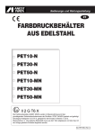
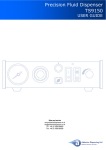
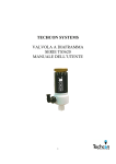
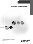
Contents
Techcon Systems
TS941 Spool Valve
1. Specifications........................................................................................... 4
2. Unpacking and inspection....................................................................... 5
User Guide
Benutzerhandbuch
Manuel d’utilisation
Valvola a spola TS941 Manuale d'uso
3. Description ............................................................................................... 5
4. Theory of operation.................................................................................. 5
5. Setup instructions.................................................................................... 6
6. Typical system setup ............................................................................... 6
7. Trouble shooting ...................................................................................... 7
8. Maintenance and cleaning....................................................................... 7
9. Spare parts and accessories................................................................... 9
10. Warranty.................................................................................................. 10
www.okinternational.it
Techcon Systems is an OK International Brand
Copyright © All Rights Reserved • TS941 Rev 04/04
2
2. Unpacking and inspection
1. Specifications
TS941
TS941A
4.7” length X 1.5” diameter
4.7” length X 1.5” diameter
(119.4mm X 38.1 mm)
(119.4mm X 38.1 mm)
Weight
1.6lb (0.728kg)
1.61lb (0.731kg)
Fluid Inlet Port
3/8”NPT female
1/4”NPT female
Fluid Outlet Port
1/4" NPT female
1/4" NPT female
Size
Carefully unpack the valve and examine the items contained in the carton.
These will include:
•
Valve Assembly
•
User Guide
• Valve Air Hose
3. Description
Air Inlet Port
1/4" NPT female
1/4" NPT female
Auxiliary Air Inlet Port
1/8” NPT
1/8” NPT
Minimum Air Pressure
70 psi
70 psi
Required
(4.8 bar)
(4.8 bar)
Maximum Fluid Pressure
2,500 psi (172 bar)
2,500 psi (172 bar)
Operating Frequency
Exceed 400 cycles/min.
Exceed 400 cycles/min.
Wetted Parts
Fluid housing (Stainless
Fluid housing (Stainless
steel), Valve spool
steel), Valve spool
(Hard Chrome plated
(Hard Chrome plated
Stainless Steel), Upper and
Stainless Steel), Upper and
Lower Seals (UHMWPE
Lower Seals (UHMWPE
Seal with EPR o-ring)
Seal with EPR o-ring)
The TS941 spool valve is based on a balanced spool design for a fast “ON/OFF”
dispensing action. The hardened spool slides in reinforced UHMWPE seals and it
suitable for use with fluids having viscosity of 100 to over 3,000,000 cps at pressure up
to 2,500 psi. An internal spring return makes the valve fully adaptable for use with
Techcon Systems time/pressure controllers.
4. Theory of operation
The TS941 valve is a normally closed spool valve. When air pressure is applied at air
inlet port (1), the spool assembly (2) moves forward to the open position, allowing the
fluid to flow from the fluid inlet port (3) to the fluid outlet port (4). Relieving the input air
pressure allows the return spring (5) to pull the spool assembly back in the close
position, stopping the fluid flow. During the closing position, the spool movement
creates a “suck-back” anti-drip feature.
An Oil chamber (6) is provided above the upper seal to create an additional liquid seal
that will prevent moisture from being carried on the spool.
The auxiliary air inlet port (7) is provided so that the valve may be connected for air
closing with or without the spring.
Open Position
Closed Position
Techcon Systems is an OK International Brand
Copyright © All Rights Reserved • TS941 Rev 04/04
Techcon Systems is an OK International Brand
Copyright © All Rights Reserved • TS941 Rev 04/04
3
4
5. Setup instructions
7. Trouble shooting
3
• Connect the fluid reservoir feed tube (1) to the valve inlet
port (2).
• Connect the valve airline (3) to the valve controller or
other pneumatic device that is used to control the valve.
• Connect appropriate nozzle or dispensing tip (4) to the
fluid outlet port.
• Set the valve controller pressure at 70 psi (4.8 bar)
• Set the fluid reservoir pressure. Do not exceed 2,500 psi
(172 bar)
• Make sure all connections are tight
• Place container under the valve outlet and activate the
valve until the fluid flows steady.
1
PROBLEM
No Fluid Flow
POSSIBLE CAUSE
Fluid pressure too low
CORRECTION
Increase fluid pressure
Operating pressure too low
Increase air pressure to 70 psi
(4.8 bar)
Replaced tip
Replaced tip
Dispense tip clogged
2
Inconsistent Fluid Flow
Fluid cured in valve chamber
Clean valve thoroughly
Fluid pressure fluctuating
Air trapped in fluid housing
Make sure fluid pressure is
constant
Increased valve pressure to
70 psi (4.8 bar)
Check to make sure the valve
controller is providing a
consistent output
Purge valve
Air trapped in fluid housing
Purge valve
Lower seal damaged or worn
Replace lower seal
Spool damaged
Replace spool
Inlet air fitting is too long,
pushing the spool in the
opened position
Upper seal damaged or worn
Replace air fitting
Valve operating pressure is
too low
Valve open time is not
consistent
The amount of fluid that flows through the valve is
determined by:
• Valve open time
• Fluid reservoir pressure
• Dispensing tip size
4
NOTE: Techcon makes an available an adjustable “suckback” cap part number 934-003-000
Fluid Drools After
The Valve Closes
But Eventually Stops
Steady Drip
6. Typical system setup
PLANT AIR MUST BE PROPERLY
FILTERED AND DRY. IF NOT, SPECIFY
A 5-MICRON FILTER REGULATOR.
Fluid Leaks Out Of The
Oil Port
Replaced upper seal
8. Maintenance and cleaning
Normally, purging the valve with appropriate flush material or solvent after use is
sufficient for cleaning. However some material may cause a buildup in the valve
chamber, in this case periodic and thorough cleaning will be required.
TS941
SPOOL VALVE
CAUTION: Make sure the fluid pressure is released before disassemble the valve.
TECHCON SYSTEMS TS5130
CONTROLLER OR EQUIVALENT
FLUID FEED SYSTEM
MATERIAL
CONSTANT AIR
1)
Release fluid pressure
2)
Disconnect fluid line
3)
Disconnect valve air line
4)
Remove end cap (1)
5)
Pull out Piston/valve spool assembly (4 )
6)
Remove the spring from air cylinder (2 )
PULSED AIR
Techcon Systems is an OK International Brand
Copyright © All Rights Reserved • TS941 Rev 04/04
Techcon Systems is an OK International Brand
Copyright © All Rights Reserved • TS941 Rev 04/04
5
6
9. Spare parts and accessories
7)
Remove socket head cap screws (10)
8)
Separate material outlet block (9), material inlet block (6) and air cylinder (3).(clean
these parts if necessary)
9)
Replace o-rings (13) on the spool shaft, material outlet block (8) and air cylinder (12)
SPARE PARTS
PART NUMBER
934-SEALKIT
941-VALVEKIT
DESCRIPTION
Seal repair kit (include O-rings, upper and lower seals)
Valve repair kit (include seal repair kit plus valve spool)
if worn or damaged.
ALTERNATIVE SEALS
10) Remove lower seals (7) out of the outlet block and upper seal (5) out of the air
cylinder using a small screw driver
11) Clean seal seats and carefully install new seals. It is important that seals should be
replaced in the same orientation to prevent leaks and accelerated wear.
Techcon Systems offers other custom seal materials for different applications.
The standard seals installed in the valve is made of UHMWPE with EPR o-ring.
The following seals are available:
PART NUMBER
TSD400-56
TSD400-58
TSD400-49
12) Lubricate O-rings with “Parker-o-lube” or similar grease
13) Assemble Material outlet block, Material inlet block and Air cylinder.
DESCRIPTION
Teflon®® seal with EPR expander O-ring
Teflon®® seal with Viton expander O-ring
Teflon®® seal with stainless steel expander spring
14) Thread Socket head cap screws into assembled valve. Tighten uniformly to ensure
ACCESSORIES
proper valve alignment.
PART NUMBER
TSD700-1
TSD700-2
15) Insert the spring back into the air cylinder.
16) Insert Piston/valve spool into valve body.
DESCRIPTION
Oiler cup, 90 degrees
Oiler cup, straight
17) Install air fitting to end cap.
18) Install End cap to air cylinder. (HAND TIGHTEN ONLY)
DISPENSING NOZZLES
• All dimensions listed are nominal
and for reference only
• Material: Polyethylene
1
2
3
4
5
6
7
8
9
Part Numer
13
12
11
10
TS216PK (50)
TS216-1000 (1000)
TS218PK (50)
TS218-1000 (1000)
TS416PK (50)
TS416-1000 (1000)
TS418PK (50)
TS418-1000 (1000)
TS432PK (50)
TS432-1000 (1000)
TS490PK (50)
TS490-1000 (1000)
TS616PK (50)
TS616-1000 (1000)
TS618PK (50)
TS618-1000 (1000)
A
(O.D.)
.44"
B
(Length)
2.6"
C
(Orifice)
.063"
.44"
2.6"
.125"
.44"
4.0"
.063"
.44"
4.0"
.125"
.44"
4.0"
.031"
.44"
4.0"
.094"
.44"
6.0"
.063"
.44"
6.0"
.125"
Note: TS416 and TS418 nozzles can also be ordered with 30, 45, 80 and 90 degree bends.
Techcon Systems is an OK International Brand
Copyright © All Rights Reserved • TS941 Rev 04/04
Techcon Systems is an OK International Brand
Copyright © All Rights Reserved • TS941 Rev 04/04
7
8
Inhalt
TIP ADAPTER
TSD931-14 – Polypropylene
918-006-000 – Metal (Brass/Stainless Steel)
1. Spezifikationen....................................................................................... 4
2. Auspacken und Überprüfen .................................................................. 5
3. Beschreibung ......................................................................................... 5
4. Funktionsweise ...................................................................................... 5
VALVE BRACKET
5. Setup-Anleitung ..................................................................................... 6
T1000268
6. Typisches System Setup ....................................................................... 6
7. Fehlersuche ............................................................................................ 7
8. Wartung und Reinigung......................................................................... 7
9. Ersatzteile und Zubehör ........................................................................ 9
10. Garantie................................................................................................. 10
10. Warranty
Manufacturer warrants this product to the original purchaser for a period of one (1) year from
date of purchase to be free from defects in material and workmanship, but not against
damages by misuse, negligence, accident, faulty installations and instructions. Manufacturer
will repair or replace (at factory’s option), free of charge, any component of the equipment
thus found to be defective, on return of the component. “PREPAID” to the factory during the
warranty period. In no event shall any liability or obligation of the Manufacturer arising from
this warranty exceed the purchase price of the equipment. This warranty is only valid if the
defective product is returned as a complete assembly without physical damage. The
Manufacturer’s liability, as stated herein, cannot be altered or enlarged except by a written
statement signed by an officer of the company. In no event shall the Manufacturer be liable
for consequential or incidental damages.
Manufacturer reserves the right to make engineering product modifications without notice.
RETURN PROCEDURE
Please contact your local Techcon Systems Representative for return procedures and
policies.
Techcon Systems is an OK International Brand
Copyright © All Rights Reserved • TS941 Rev 04/04
Techcon Systems is an OK International Brand
Copyright © All Rights Reserved • TS941 Rev 04/04
9
10
2. Auspacken und Überprüfen
1. Spezifikationen
Größe
TS941
TS941A
4,7” Länge X 1,5”
4,7” Länge X 1,5”
Durchmesser
Durchmesser
(119,4 mm X 38,1 mm)
(119,4 mm X 38,1 mm)
Gewicht
1,6lb (0,728 kg)
0,73kg (0,731kg)
Materialeinlass
3/8”NPT Innengewinde
1/4”NPT Innengewinde
Materialauslass
1/4" NPT Innengewinde
1/4" NPT Innengewinde
Drucklufteingang
1/4" NPT Innengewinde
1/4" NPT Innengewinde
Zusätzlicher Drucklufteingang
1/8” NPT
1/8” NPT
Mindest-Luftdruck
70 psi
70 psi
(4,8 bar)
(4,8 bar)
Maximaler Materialdruck
2.500 psi (172 bar)
2.500 psi (172 bar)
Betriebsfrequenz
Mehr als 400 Zyklen/min.
Mehr als 400 Zyklen/min.
Benetzte Teile
Gehäuse (Edelstahl),
Gehäuse (Edelstahl),
Kolbenventil
Kolbenventil
(hartverchromter Edelstahl),
(hartverchromter Edelstahl),
obere und untere Dichtung
obere und untere Dichtung
(UHMWPE Dichtung mit
(UHMWPE Dichtung mit
EPR O-Ring)
EPR O-Ring)
LUFTEINGANG
1/4 NPT
ABLUFTÖFFNUNG
1/4 NPT
MATERIALEINLASS
3/8 NPT
Packen Sie das Ventil vorsichtig aus, und überprüfen Sie die im Karton enthaltenen
Einheiten.
Dazu gehören:
•
Ventileinheit
•
Benutzerhandbuch
• Ventil-Druckluftschlauch
3. Beschreibung
Das TS941-Hochdruck-Kolbenventil wurde so konstruiert, dass der Kolben das Ventil
sehr schnell öffnet – und wieder schließt, was einen hohen Dosierzyklus sicherstellt. Es
weist ein Rückhaltevakuum auf, mit dem Nachtropfen vermieden und beim Schließen
ein sauberer Abriss gewährleistet wird.. Der gehärtete Kolben läuft in verstärkten
UHMWPE-Dichtungen und eignet sich für Dosiermedien, die über eine Viskosität von
100 bis mehr als 3.000.000 cps bei einem Druck bis zu 172 bar / 2.500 psi verfügen.
Das Ventil ist optimal für den Einsatz von Techcon Controllern ausgelegt.
4. 4. Funktionsweise
Das TS941-Ventil ist ein geschlossenes Kolbenventil. Durch den Drucklufteingang wird
dem Ventil Druckluft (1) zugeführt. Dadurch bewegt sich die Kolbeneinheit (2) nach
vorn in die geöffnete Stellung, so dass das Dosiermedium vom Materialeinlass (3) zum
Ausgang (4) fließt. Durch Unterbrechung der Druckluftzufuhr zieht die Feder (5) die
Kolbeneinheit zurück in die geschlossene Stellung, und unterbricht so das Austreten
des Mediums. Durch den Rückzug des Kolbens entsteht ein Rückhaltevacuum, mit
dem Nachtropfen vermieden wird.
Über der oberen Dichtung befindet sich eine Ölkammer, die als eine sogenannte
„Flüssigdichtung“ fungiert. Diese verhindert, dass Feuchtigkeit an den Kolben gelangt.
Der zusätzliche Drucklufteingang (7) dient dazu, das Ventil optional mit oder ohne
Feder, schneller schließen zu können.
Geöffnete Stellung
MATERIALAUSLASS
1/4 NPT
Geschlossene Stellung
ÖLANSCHLUSS 1/8 NPT
Techcon Systems is an OK International Brand
Copyright © All Rights Reserved • TS941 Rev 04/04
Techcon Systems is an OK International Brand
Copyright © All Rights Reserved • TS941 Rev 04/04
11
12
5. Setup-Anleitung
7. Fehlersuche
3
• Verbinden Sie die Schlauchleitung des Mediumbehälters (1)
(z.B. Kartusche) mit dem Ventileingang (2).
• Verbinden Sie den Drucklluftschlauch (3) mit dem Controller
oder einer anderen pneumatischen Kontrolleinheit, die zur
Steuerung des Ventils dient.
• Verbinden Sie die entsprechende Düse oder Dosiernadel (4)
mit dem Materialauslass.
• Stellen Sie den Druck am Controller auf 70 psi (4,8 bar) ein.
• Bestimmen Sie den Druck der Materialzufuhrleitung.
Überschreiten Sie nicht 2.500 psi (172 bar).
• Achten Sie darauf, dass alle Verbindungen fest sitzen.
• Platzieren Sie einen Behälter unter dem Ventilausgang and
aktivieren Sie das Ventil, bis das Dosiermedium konstant
fließt.
Die Dosiermenge, die durch das Ventil fließt, wird bestimmt
durch:
• Die Ventilöffnungszeit
• Den Materialdruck
• Die Größe der Dosiernadel
1
PROBLEM
Kein Materialfluß
MÖGLICHE URSACHE
Materialdruck zu niedrig
BESEITIGUNG
Materialdruck erhöhen
Betriebsdruck zu niedrig
Luftdruck auf 70 psi (4,8 bar)
erhöhen
Dosiernadel ersetzen
Dosiernadel verstopft
Medium in Ventilkammer
verhärtet
Schwankender Materialdruck
2
Ungleichmäßiger
Materialfluß
Ventil gründlich reinigen
Luft im Materialgehäuse
Sicherstellen, dass der
Materialdruck konstant ist
Ventildruck auf 70 psi (4,8
bar) erhöhen
Sicherstellen, dass der
Controller konstant Druckluft
liefert.
Ventil reinigen
Luft im Materialgehäuse
Ventil reinigen
Untere Dichtung beschädigt
oder abgenutzt
Untere Dichtung ersetzen
Kolben beschädigt
Kolben ersetzen
Gewinde des
Drucklufteinlassadapter ist zu
lang, so dass Kolben in
geöffnete Stellung gedrückt
wird
Obere Dichtung beschädigt
oder abgenutzt
Drucklufteinlassadapter
ersetzen
Betriebsdruck des Ventils zu
niedrig
Ventilöffnungszeit nicht
gleichmäßig
4
Medium fließt weiter,
nachdem das Ventil
geschlossen wurde,
stoppt jedoch allmählich
HINWEIS: Techcon stellt optional eine einstellbare „VakuumRückhalte“-Kappe, Teilenummer 934-003-000, zur Verfügung.
6. Typisches System Setup
Stetiges Tropfen
PLANT AIR MUST BE PROPERLY
DRUCKLUFT
MUSS ORDNUNGSGEMÄSS GEFILTERT UND TROCKEN SEIN.
FILTERED AND DRY. IF NOT, SPECIFY
WENNA 5-MICRON
NICHT, MONTIEREN
SIE EINEN 5-MICRON FILTERREGLER.
FILTER REGULATOR.
Medium tritt aus dem
Ölkanal aus
TS941
KOLBENVENTIL
SPOOL VALVE
Obere Dichtung ersetzen
8. Wartung und Reinigung
Normalerweise reicht es aus, das Ventil mit einem geeigneten Spülmittel oder einer
Lösung zu säubern. Bestimmte Medien führen jedoch zu Ablagerungen in der
Ventilkammer; in diesem Fall ist eine regelmäßige und gründliche Reinigung
erforderlich.
TECHCON SYSTEMS TS5130
CONTROLLER OR EQUIVALENT
CONTROLLER
ODER ÄHNLICHES
FLUID FEED SYSTEM
DRUCKTANK
ACHTUNG: Achten Sie darauf, dass der Materialdruck abgebaut wurde, bevor Sie das
Dosiermedium
MATERIAL
Ventil demontieren.
Konstante
Druckluft
CONSTANT
AIR
Gepulste
Druckluft
PULSED AIR
Techcon Systems is an OK International Brand
Copyright © All Rights Reserved • TS941 Rev 04/04
Techcon Systems is an OK International Brand
Copyright © All Rights Reserved • TS941 Rev 04/04
13
14
9. Ersatzteile und Zubehör
1)
Reduziere Sie den Materialdruck
2)
Lösen Sie die Materialleitung
3)
Lösen Sie die Druckluftleitung
4)
Entfernen Sie die Abschlusskappe (1)
5)
Ziehen Sie die Kolben-/Ventilkolbeneinheit (4) heraus
6)
Entfernen Sie die Feder vom Luftzylinder (2)
7)
Entfernen Sie die Inbusschrauben (10)
8)
Trennen Sie die Ventilkopf (9), Materialeingangsgehäuse (6) und den Druckluftzylinder
(3). (Reinigen Sie diese Komponenten, falls erforderlich)
9)
Ersetzen Sie die O-Ringe (13) auf der Ventilschaft, des Ventilkopfes(8) und dem
Druckluftzylinder (12), falls diese abgenutzt oder beschädigt sind.
ERSATZTEILE
TEILENUMMER
934-SEALKIT
934-VALVEKIT
BESCHREIBUNG
Dichtungsreparatursatz (einschließlich O-Ringe, obere
und untere Dichtungen)
Ventil-Reparatursatz (einschließlich
Dichtungsreparatursatz und Ventilkolben)
ALTERNATIVE DICHTUNGEN
Techcon Systems bietet andere gängige Dichtungswerkstoffe für unterschiedliche
Anwendungen an.
Die Standard-Dichtungen, die im Ventil eingebaut sind, bestehen aus UHMWPE mit
EPR O-Ring.
Folgende Dichtungen stehen zur Verfügung:
TEILENUMMER
TSD400-56
TSD400-58
TSD400-49
10) Entfernen Sie die unteren Dichtungen (7) vom Ventilkopf und die obere Dichtung (5)
vom Druckluftzylinder mit Hilfe eines kleinen Schraubendrehers
11) Reinigen Sie den Dichtungssitz, und setzen Sie neue Dichtungen ein. Es ist wichtig,
dass Dichtungen in der gleichen Ausrichtung eingesetzt werden, um Leckagen und
eine beschleunigte Abnutzung zu vermeiden.
BESCHREIBUNG
Teflon®-Dichtung mit EPR Expander-O-Ring
Teflon®-Dichtung mit Viton Expander-O-Ring
Teflon®-Dichtung mit Edelstahl-Expanderfeder
ZUBEHÖR
TEILENUMMER
TSD700-1
TSD700-2
12) Schmieren Sie die O-Ringe mit „Parker O-Lube“ oder einem ähnlichen Schmiermittel
BESCHREIBUNG
Ölbuchse, 90 Grad
Ölbuchse, gerade
1/8 NPT
1/8 NPT
13) Montieren Sie den Ventilkopf, Materialeingangsgehäuse und den Druckluftzylinder.
DISPENSDÜSEN
14) Schrauben Sie die Inbusschrauben in denVentilkopf. Ziehen Sie die Schrauben
gleichmäßig an, so dass das Ventil ordnungsgemäß ausgerichtet ist.
•
•
Alle aufgelisteten Abmessungen sind Nennwerte
und gelten ausschließlich zu Referenzzwecken
Material: Polyethylen
15) Setzen Sie die Feder wieder in den Druckluftzylinder ein.
Artikelnummer
1
2
3
4
5
6
7
8
9
Hinweis: TS416 und TS418 Düsen können auch mit 30,
45, 80 und 90 Grad Krümmung bestellt werden.
MATERIALAUSLASSADAPTER
TSD931-14 – Polypropylen _ NPT Luer Lock
918-006-000 – Metall (Messing/Edelstahl) _ NPT Luer Lock
13
12
11
10
Techcon Systems is an OK International Brand
Copyright © All Rights Reserved • TS941 Rev 04/04
Techcon Systems is an OK International Brand
Copyright © All Rights Reserved • TS941 Rev 04/04
15
16
VENTILTRÄGER
T1000268
Sommaire
1. Spécifications......................................................................................... 4
10. EINGESCHRÄNKTE GARANTIE
2. Déballage et contrôle ............................................................................. 5
Der Hersteller übernimmt gegenüber dem Originalkäufer für dieses Produkt eine Garantie für
Material- und Verarbeitungsfehler für den Zeitraum von einem (1) Jahr ab Kaufdatum,
ausgeschlossen hiervon sind jedoch Schäden durch Missbrauch, Fahrlässigkeit, Unfall,
fehlerhafte Installationen und Anweisungen. Der Hersteller repariert oder ersetzt nach
eigenem Ermessen kostenlos alle fehlerhaften Bestandteile des Gerätes, nachdem dieses
auf Kosten des Erstkäufers während der Garantiezeit an den Hersteller zurückgesendet
wurde. Jegliche Haftung oder Verpflichtung seitens des Herstellers, die aus dieser
Gewährleistung resultiert, ist auf den Kaufpreis des Ventils beschränkt. Diese Gewährleistung
gilt nur, wenn das fehlerhafte Produkt als komplette Einheit ohne physikalischen Schaden
zurückgesendet wird. Die hier beschriebene Haftung des Herstellers kann nur durch eine
schriftliche Erklärung, die von einem Mitarbeiter der Firma unterschrieben wurde, geändert
oder erweitert werden. Der Hersteller haftet unter keinen Umständen für Folgeschäden oder
zufällige Schäden. Vor Sendung einer fehlerhaften Einheit ans Werk wird eine
Rücksendegenehmigung von OK International GmbH benötigt.
Der Hersteller behält sich das Recht vor, technische Produktänderungen ohne
Vorankündigung vorzunehmen.
3. Description ............................................................................................. 5
4. Principe de fonctionnement .................................................................. 5
5. Instructions de montage........................................................................ 6
6. Configuration système typique............................................................. 6
7. Dépannage.............................................................................................. 7
8. Maintenance et nettoyage ..................................................................... 7
9. Pièces détachées et accessoires.......................................................... 9
10. Garantie................................................................................................. 10
Techcon Systems is an OK International Brand
Copyright © All Rights Reserved • TS941 Rev 04/04
Techcon Systems is an OK International Brand
Copyright © All Rights Reserved • TS941 Rev 04/04
17
18
1. Spécifications
Dimensions
TS941
TS941A
Longueur 4,7" X diamètre
Longueur 4,7" X diamètre
1,5" (119,4mm X 38,1 mm)
1,5" (119,4mm X 38,1 mm)
Poids
1.6 lb (728 g)
1.61 lb (731 g)
Raccord d'entrée du fluide
3/8”NPT femelle
1/4”NPT femelle
Raccord de sortie du fluide
1/4”NPT femelle
1/4”NPT femelle
Raccord d'entrée d'air
1/4”NPT femelle
1/4”NPT femelle
Raccord d'entrée d'air
1/8”NPT
1/8”NPT
Pression minimale d'air
70 psi
70 psi
nécessaire
(4,8 bar)
(4,8 bar)
Pression maximale du fluide
2,500 psi (172 bar)
2,500 psi (172 bar)
Fréquence de
Plus de 400 cycles/min.
Plus de 400 cycles/min.
Corps (acier inox),
Corps (acier inox),
Piston (acier inoxydable
Piston (acier inoxydable
chromé dur), joints supérieur
chromé dur), joints supérieur
et inférieur (joint UHMWPE
et inférieur (joint UHMWPE
avec joint torique EPR)
avec joint torique EPR)
auxiliaire
fonctionnement
Matériaux
RACCORD
D’ENTREE D’AIR
1 / 4 NPT
RACCORD DE SORTIE
D’AIR
1 / 8 NPT
RACCORD D’ENTREE
DE FLUIDE
3 / 8 NPT
RACCORD D’ENTREE D’HUILE
1 / 8 NPT
Techcon Systems is an OK International Brand
Copyright © All Rights Reserved • TS941 Rev 04/04
Techcon Systems is an OK International Brand
Copyright © All Rights Reserved • TS941 Rev 04/04
19
20
RACCORD DE SORTIE
DE FLUIDE
1 / 4 NPT
2. Déballage Et Contrôle
5. Instructions De Montage
3
Déballez soigneusement la valve et examinez soigneusement les éléments contenus dans
le carton.
Ces éléments sont les suivants :
•
Valve
•
Guide de l'utilisateur
• Tuyau d'air de la valve
3. Description
La valve à piston TS941 est commandée pneumatiquement, assurant une action rapide
“OUVERTE/FERMEE” de dosage. Le piston glisse à l'intérieur d'un joint UHMWPE renforcé,
et permet l'utilisation de fluides d'une viscosité de 100 à plus de 3 000 000 cps, sous une
pression allant jusqu'à 2 500 psi. Un ressort de rappel interne rend la valve totalement
adaptée à l'utilisation avec les contrôleurs temps/pression de Techcon Systems.
4. Principe De Fonctionnement
Au repos, la valve est fermée. Lorsque la pression d'air est appliquée au raccord d'entrée
d'air (1), le piston (2) se déplace en position avant, permettant au fluide de s'écouler du
raccord d'entrée du fluide (3) vers le raccord de sortie du fluide (4). La chute de pression de
l'entrée d'air permet au ressort de rappel (5) de ramener le piston en position fermée,
interrompant l'écoulement du fluide. En revenant en position fermée, le mouvement du
psiton crée un effet “suck-back” (ré-aspiration) anti-goutte.
Un huileur (6) peut être monté (option), l’huile créant une barrière pour les produits
sensibles à l’humidité.
Le raccord d'entrée d'air auxiliaire (7) permet de raccorder la valve à une commande de
fermeture, avec ou sans le ressort.
1
• Raccordez le tube d'alimentation venant du réservoir de
fluide (1) au raccord d'entrée de la valve (2).
• Raccordez la ligne d'air de la valve (3) au contrôleur de
valve ou à l'équipement pneumatique utilisé pour commander
la valve.
• Connectez la buse appropriée ou l’aiguille de dosage (4) au
raccord de sortie de fluide.
• Réglez la pression de commande de la valve à 70 psi (4,8
bar)
• Établissez la pression dans le réservoir de fluide. Ne
dépassez pas 2 500 psi (172 bar).
• Assurez-vous que tous les raccordements sont étanches.
• Placez un récipient sous la sortie de la valve et actionnez la
valve jusqu'à ce que le fluide s'écoule en continu.
La quantité de fluide qui s'écoule à travers la valve est
déterminée par :
• Le temps d'ouverture de la valve
• La pression du réservoir de fluide
• La taille de la tête de dosage
2
4
NOTE : Techcon fabrique un embout “suck-back” (ré-aspiration)
réglable sous la référence 934-003-000
6. Configuration Système Typique
PLANT AIR MUST BE PROPERLY
L’AIRFILTERED
D’ALIMENTATION
DOIT ETRE FILTRE ET SEC. SI CE N’EST PAS LE CAS, UTILISEZ UN
AND DRY. IF NOT, SPECIFY
REGULATEUR
5 FILTRES MICRONS
A 5-MICRON AVEC
FILTER REGULATOR.
Position Ouverte
TS941
VALVE
A
SPOOL VALVE
PISTON
TS941
Position Fermée
TECHCON SYSTEMS TS5130
CONTROLLER OR EQUIVALENT
TECHCON
SYSTEMS TS5130 OU EQUIVALENT
1
Produit
MATERIAL
AirCONSTANT
Permanent
AIR
AirPULSED
Pulsé AIR
Techcon Systems is an OK International Brand
Copyright © All Rights Reserved • TS941 Rev 04/04
Techcon Systems is an OK International Brand
Copyright © All Rights Reserved • TS941 Rev 04/04
21
22
FLUID FEED SYSTEM
SYSTEME D'ALIMENTATION
DU FLUIDE
7. Dépannage
PROBLEME
Le fluide ne s'écoule pas
Écoulement irrégulier du
fluide
CAUSE POSSIBLE
La pression de fluide est trop
basse
CORRECTION
Augmenter la pression du
fluide
La pression de commande est
trop basse
La tête de dosage est
bouchée
Le fluide a séché dans le
corps de la valve
Augmenter la pression d'air à
70 psi (4,8 bar)
Remplacer la tête
La pression du fluide est
fluctuante
La pression de commande de
la valve est trop basse
La durée d'ouverture de la
vanne est irrégulière
Vérifier que la pression est
constante
Augmenter la pression d'air à
70 psi (4,8 bar)
Vérifier que le contrôleur de
vanne fournit une sortie
régulière
Purger la valve
De l'air est piégé dans le
circuit de fluide
Du fluide suinte après
que la valve est fermée,
mais s'arrête parfois
Nettoyer soigneusement la
valve
De l'air est piégé dans le
circuit de fluide
Purger la valve
Le joint inférieur est
endommagé ou usé
Remplacer le joint inférieur
Le piston est endommagée
Le raccord d'entrée d'air est
trop long, et pousse l'aiguille
en position ouverte
Le joint supérieur est
endommagé ou usé
Remplacer le piston
Remplacer le raccord d'air
4)
Retirez l’embout (1)
5)
Retirez le piston/l'aiguille (4) de la valve
6)
Retirez le ressort du cylindre pneumatique (2)
7)
Retirez les vis de fixation de la tête (10)
8)
Séparez le bloc de sortie du produit (9), le bloc d'entrée du produit (6) et le cylindre
pneumatique (3)
9)
Remplacez les joints toriques (13) du piston, le bloc de sortie du produit (8) et le
cylindre pneumatique (12), s'ils sont usés ou endommagés.
10) Retirez le joint inférieur (7) de bloc de sortie et le joint supérieur (5) du cylindre
pneumatique au moyen d'un petit tournevis.
11) Nettoyez les portées de joints et mettez en place de nouveaux joints. Il est important
de remettre les joints en place avec la même orientation pour éviter les fuites et une
usure accélérée.
12) Lubrifiez les joint toriques avec du “Parker-o-lube”, ou avec une graisse similaire.
13) Remontez le bloc de sortie du produit, le bloc d'entrée du produit et le cylindre
pneumatique.
14) Remettez en place les vis de maintien de la tête dans le corps de la valve. Serrez de
manière uniforme pour assurer un bon alignement de la valve.
15) Remettez le ressort dans le cylindre pneumatique.
La valve fuit
constamment
Du fluide s'écoule par le
raccord d'huile
1
2
3
4
5
6
7
8
9
Remplacer le joint supérieur
8. Maintenance et nettoyage :
Normalement, il suffit de purger la valve avec un produit de rinçage ou un solvant approprié après
usage pour la nettoyer. Cependant, certains produits peuvent provoquer des dépôts dans le
corps de la valve. Dans ce cas, un nettoyage périodique minutieux peut être nécessaire.
ATTENTION : Vérifiez que la pression du fluide est éliminée avant de démonter la valve.
13
1)
Évacuez la pression du fluide
2)
Déconnectez la ligne de fluide
3)
Déconnectez la ligne d'air de commande de la valve
12
Techcon Systems is an OK International Brand
Copyright © All Rights Reserved • TS941 Rev 04/04
Techcon Systems is an OK International Brand
Copyright © All Rights Reserved • TS941 Rev 04/04
23
24
11
10
9. Pièces Détachées Et Accessoires
PIÈCES DÉTACHÉES
RÉFÉRENCE
941-SEALKIT
941-VALVEKIT
DESCRIPTION
Kit de réparation de joints (comprend les joints toriques,
le joint supérieur et le joint inférieur)
Kit de réparation de la valve (comprend le kit de
réparation des joints plus l'aiguille de valve)
SUPPORT DE VALVE
T1000268
AUTRES JOINTS
Techcon Systems propose des joints dans d'autres matériaux pour différentes
applications.
Les joints standards installés dans la valve sont fabriqués à partir de UHMWPE avec
des joints toriques EPR.
Les joints suivants sont disponibles :
RÉFÉRENCE
TSD400-56
TSD400-58
TSD400-49
DESCRIPTION
Joint Teflon® avec joint torique EPR à expansion
Joint Teflon® avec joint torique Viton à expansion
Joint Teflon® avec anneau d'expansion en acier
inoxydable
ACCESSOIRES
RÉFÉRENCE
TSD700-1
TSD700-2
DESCRIPTION
Huileur à 90 degrés
Huileur droit
10. GARANTIE LIMITÉE
Le fabricant garantit ce produit à l'acheteur original pour une période d'un (1) an à partir de la
date d'achat contre les défauts de matière et de fabrication, mais pas contre les dommages
liés à une mauvaise utilisation, une négligence, un accident, une installation ou des
instructions erronées. Le fabricant réparera ou remplacera (au choix de l'usine) gratuitement
les composants de l'équipement dont la défectuosité aura été prouvée, après retour du
composant en "Port payé" à l'usine, pendant la période de garantie. En aucun cas la
responsabilité ou les obligations du fabricant résultant de cette garantie ne pourront dépasser
le prix d'achat de l'équipement. La garantie ne s'applique que si le produit défectueux est
renvoyé complètement monté, sans présenter de dommage physique. La responsabilité du
fabricant, décrite ici, ne peut être modifiée ou élargie, sauf accord écrit signé par un
responsable de la société. En aucun cas le fabricant ne pourra être tenu responsable des
dommages accidentels ou consécutifs. Une autorisation de retour doit être demandée à
Techcon Systems avant de renvoyer une unité défectueuse à l'usine.
Le fabricant se réserve de procéder sans préavis à toute modification du produit ou de sa
fabrication.
Les retours sous garantie doit être envoyés à votre revendeur ou distributeur Techcon local
BUSES DE DOSAGE
•
•
Les dimensions listées ci-dessous sont nominales
et pour référence seulement
Matériaux: Polyéthylene
Référence
NB: Les buses TS416 et TS418 sont aussi disponibles
o
o
o
o
avec des angles coudés de 30 , 45 , 80 et 90 .
ADAPTATEUR POUR AICUILLES DE DOSAGE
TSD931-14 – Polypropylène
918-006-000 – Métal (laiton/acier inox)
Techcon Systems is an OK International Brand
Copyright © All Rights Reserved • TS941 Rev 04/04
Techcon Systems is an OK International Brand
Copyright © All Rights Reserved • TS941 Rev 04/04
25
26
1. Specifiche
Indice
Dimensioni
TS941
TS941A
4.7” di lunghezza X 1.5” di
4.7” di lunghezza X 1.5” di
diametro (119.4mm X 38.1
diametro (119.4mm X 38.1
mm)
mm)
1. Specifiche ............................................................................................... 4
Peso
1.6lb (0.728kg)
1.61lb (0.731kg)
2. Disimballaggio e controllo .................................................................... 5
Porta d’ingresso fluido
3/8”NPT femmina
1/4”NPT femmina
Porta di uscita fluido
1/4" NPT femmina
1/4" NPT femmina
3. Descrizione ............................................................................................. 5
4. Teoria di funzionamento........................................................................ 5
5. Istruzioni per l’installazione .................................................................. 6
6. Installazione tipica del sistema............................................................. 6
Porta d’ingresso aria
1/4" NPT femmina
1/4" NPT femmina
Porta d’ingresso aria per
1/8”NPT
1/8”NPT
Pressione dell’aria minima
70 psi
70 psi
richiesta
(4,8 bar)
(4,8 bar)
Pressione massima del fluido
2,500 psi (172 bar)
2,500 psi (172 bar)
Frequenza d’esercizio
Superiore a 400 cicli/min.
Superiore a 400 cicli/min.
Parti bagnate dal fluido
Camera ingresso fluido
Camera ingresso fluido
(acciaio inossidabile),
(acciaio inossidabile),
Camera uscita fluido
Camera uscita fluido
(acciaio inossidabile duro
(acciaio inossidabile duro al
cromato), guarnizioni
cromo), guarnizioni superiori
superiori ed inferiori
ed inferiori (guarnizione
(guarnizione UHMWPE con
UHMWPE con o-ring EPR)
ritorno
7. Localizzazione guasti............................................................................. 7
8. Manutenzione e pulizia .......................................................................... 7
9. Ricambi ed accessori............................................................................. 9
10. Garanzia ................................................................................................ 10
o-ring EPR)
PORTA
D’INGRESSO
DELL’ARIA
1/4 NPT
PORTA DI RITORNO
DELL’ARIA
1/4 NPT
PORTA D’INGRESSO
DEL MATERIALE
3/8 NPT
PORTA A TENUTA DELL’OLIO
Techcon Systems is an OK International Brand
Copyright © All Rights Reserved • TS941 Rev 04/04
Techcon Systems is an OK International Brand
Copyright © All Rights Reserved • TS941 Rev 04/04
27
28
PORTA D’USCITA DEL
MATERIALE
1/4 NPT
2. Disimballaggio E Controllo
5. Istruzioni Per L’installazione
3
Disimballare accuratamente la valvola ed esaminare gli articoli contenuti nella scatola.
Essa contiene:
•
gruppo valvola
•
guida dell’utente
•
tubo flessibile per aria compressa
3. Descrizione
La valvola a spola TS941 si basa su di un sistema a spola bilanciata che consente di
ottenere una rapida azione “ON/OFF” di dosaggio. La spola temprata scorre all’interno di
guarnizioni UHMWPE rinforzate ed è indicato per le applicazioni che prevedono l’uso di
fluidi dalla viscosità variabile da 100 a 3.000.000 cps e più, fino ad una pressione 172 Bar.
Il ritorno a molla interno rende la valvola perfettamente indicata per l’uso con le centraline
tempo/pressione Techcon Systems.
4. Teoria Di Funzionamento
La valvola TS941 è una valvola a spola normalmente chiusa. Immettendo aria compressa
nella porta d’immissione (1), la spola (2) si sposta in avanti in posizione aperta consentendo
in questo modo al fluido di scorrere dalla porta d’immissione del fluido stesso (3) a quella di
uscita (4). Quando la pressione dell’aria compressa viene scaricata, la molla (5) fa ritornare
la spola in posizione chiusa interrompendo il flusso del fluido. Il movimento della spola crea
un effetto di “risucchio” antigocciolamento.
Sopra alla guarnizione superiore vi è una camera d’olio (6) che serve a creare una barriera
per impedire che l’umidità venga trasportata dalla spola all’interno della camera. Inoltre
lubrifica la spola stessa.
1
• Collegare il tubo flessibile di alimentazione del fluido dal
serbatoio (1) alla porta d’ingresso della valvola (2).
• Collegare il tubo dell’aria della valvola (3) alla centralina o
ad altro dispositivo pneumatico utilizzato per comandare la
valvola stessa.
• Collegare un adeguato ugello (4) alla porta di uscita del
fluido.
• Regolare la pressione della centralina a 70 psi (4.8 bar)
• Regolare la pressione del serbatoio del fluido senza
superare 2.500 psi (172 bar)
• Controllare la tenuta di tutti gli allacciamenti
• Posizionare un contenitore sotto l’uscita della valvola ed
attivare quest’ultima fino a quando il fluido non fluisce
uniformemente.
2
La quantità di fluido che fluisce attraverso la valvola è
determinata da:
• tempo di apertura della valvola
• pressione del fluido
• dimensioni dell’ugello
4
NOTA: Techcon produce un dispositivo di regolazione del
risucchio (codice articolo 934-003-000) acquistabile a parte
6. Installazione Tipica Del Sistema
La porta ausiliare (7) è predisposta in modo che la valvola possa essere chiusa anche con
pressione d’aria
L’aria
compressa
deve
essere asciutta ed opportunamente filtrata. Nel caso adottare un regolatore di
PLANT
AIR MUST BE
PROPERLY
FILTERED AND
SPECIFY
pressione
conDRY.
filtroIF 5NOT,
micron.
A 5-MICRON FILTER REGULATOR.
Posizione aperta
Valvola
TS941 a
SPOOL
VALVE
spola
TS941
TECHCON SYSTEMS TS5130
CONTROLLER
ORcontrollo
EQUIVALENT
Centralina di
Posizione chiusa
FLUID FEED SYSTEM
Sistema di
alimentazione del fluido
TS5130 o equivalente
1
Materiale
MATERIAL Fluido
Aria
Costante
CONSTANT
AIR
Aria
Pulsata
PULSED
AIR
Techcon Systems is an OK International Brand
Copyright © All Rights Reserved • TS941 Rev 04/04
Techcon Systems is an OK International Brand
Copyright © All Rights Reserved • TS941 Rev 04/04
29
30
8. Manutenzione E Pulizia
7. Localizzazione Guasti
PROBLEMA
POSSIBILE CAUSA
CORREZIONE
Manca flusso di fluido
La pressione del fluido è
troppo bassa
Aumentare la pressione del
fluido
La pressione di comando è
troppo bassa
Aumentare la pressione
dell’aria a 70 psi (4.8 bar)
L’ago di dosaggio è ostruito
Sostituire l’ago
Fluido indurito nella camera
della valvola
Pulire accuratamente la
valvola
Pressione del fluido fluttuante
Rendere costante la
pressione del fluido
La pressione di comando
della valvola è troppo bassa
Aumentare la pressione della
valvola a 70 psi (4.8 bar)
Normalmente per pulire la valvola basta spurgarla con un materiale o solvente adeguato dopo
averla utilizzata. Tuttavia alcuni materiali possono provocare la formazione di depositi all’interno
della camera della valvola. In tal caso è richiesta un’accurata e periodica pulizia della valvola.
ATTENZIONE: accertarsi che la pressione del fluido sia scaricata prima di smontare la valvola.
1)
2)
3)
4)
5)
6)
7)
8)
9)
10)
Flusso irregolare del
fluido
11)
12)
13)
14)
Il tempo di apertura della
valvola non è costante
Controllare e fare in modo che
la centralina di controllo
assicuri un’erogazione
costante
Aria intrappolata nel fluido
all’uscita della valvola
Spurgare la valvola
Perdita temporanea di
fluido dopo la chiusura
della valvola
Aria intrappolata nel fluido
all’uscita della valvola
Spurgare la valvola
Ingrandire l’ago di dosatura
Gocciolamento costante
Guarnizione inferiore
danneggiata o usurata
Sostituire la guarnizione
inferiore
La spola è danneggiata
Sostituire la spola
La guarnizione superiore è
danneggiata o usurata
Sostituire la guarnizione
superiore
Fuoriuscita di fluido dalla
porta dell’olio
Techcon Systems is an OK International Brand
Copyright © All Rights Reserved • TS941 Rev 04/04
31
15)
16)
17)
18)
Scaricare la pressione del fluido
Scollegare il raccordo del fluido
Scollegare il raccordo dell’aria di comando della valvola
Togliere il cappuccio terminale (1)
Estrarre il pistone/il gruppo della spola (4 )
Togliere la molla dal cilindro pneumatico (2 )
Togliere le viti a brugola (10)
Separare e, se necessario, pulire il blocco d’uscita del materiale (9), il blocco
d’ingresso del materiale (6) ed il cilindro pneumatico (3).
Sostituire gli o-ring (13) dell’albero della spola , il blocco della porta di scarico del
materiale (8) ed il cilindro pneumatico (12) se usurati o danneggiati.
Estrarre le guarnizioni inferiori (7) dal blocco d’uscita e la guarnizione superiore (5) dal
cilindro pneumatico utilizzando un piccolo cacciavite
Pulire le sedi delle guarnizioni e montare con cura quelle nuove. E’ importante che le
guarnizioni di sostituzione siano orientate nello stesso senso in modo da prevenire
eventuali fuoriuscite ed una usura precoce.
Lubrificare gli o-ring con un grasso neutro
Montare il blocco della porta di uscita del materiale, il blocco della porta d’ingresso ed il
cilindro pneumatico.
Inserire le viti a brugola nella valvola montata. Stringerle in modo uniforme per
assicurare il corretto allineamento della valvola.
Reinserire la molla all’interno del cilindro pneumatico.
Inserire il pistone/la spola all’interno del corpo della valvola.
Montare il raccordo per l’aria sul cappuccio terminale.
Installare il cappuccio terminale sul cilindro pneumatico. (STRINGERE SOLO
MANUALMENTE)
1
2
3
4
5
6
7
Techcon Systems is an OK International Brand
13All Rights Reserved
12 • TS941 Rev 04/04 11
Copyright ©
32
8
9
10
9. Ricambi Ed Accessori
RICAMBI
CODICE ARTICOLO
934-SEALKIT
934-VALVEKIT
STAFFA PER VALVOLA
DESCRIZIONE
Kit di riparazione guarnizioni (contiene o-ring,
guarnizioni superiori ed inferiori)
Kit di riparazione valvola (contiene kit di riparazione per
guarnizioni più rocchetto)
T1000268
GUARNIZIONI ALTERNATIVE
10. GARANZIA LIMITATA
La Techcon Systems offre altri materiali di guarnizione realizzati su misura per diverse
applicazioni. La guarnizione standard installata nella valvola è fatta di UHMWPE con oring EPR.
Sono disponibili le seguenti guarnizioni:
CODICE ARTICOLO
TSD400-56
TSD400-58
TSD400-49
DESCRIZIONE
Guarnizione di Teflon® con o-ring EPR ad espansione
Guarnizione di Teflon® con o-ring Viton ad espansione
Guarnizione di Teflon® con molla ad espansione in
acciaio inossidabile
ACCESSORI
CODICE ARTICOLO
TSD700-1
TSD700-2
DESCRIZIONE
Tazza oliatore, 90 gradi
Tazza oliatore, diritta
Il produttore garantisce all’acquirente iniziale per un periodo di un (1) anno dalla data
d’acquisto che il prodotto in oggetto è esente da difetti materiali e di lavorazione. Il prodotto
tuttavia non è garantito contro danni derivanti da uso improprio, negligenza, incidenti ed
errate installazioni o istruzioni. Pertanto la casa produttrice provvederà alla riparazione o
sostituzione (a propria discrezione) gratuita di qualsiasi componente del dispositivo che risulti
essere difettoso una volta restituito. “PAGATO ANTICIPATAMENTE” alla fabbrica durante il
periodo di garanzia. In nessun caso la casa produttrice dovrà far fronte a responsabilità ed
obblighi derivanti dalla presente garanzia per importi superiori al prezzo d’acquisto del
dispositivo. La presente garanzia è valida solamente se il prodotto difettoso viene restituito
nella sua interezza e senza danni fisici. La responsabilità della casa produttrice definita in
questi termini non può essere modificata o ampliata in alcun modo se non tramite
dichiarazione scritta controfirmata da un dirigente della società. In nessun caso la casa
produttrice sarà responsabile di danni indiretti o accidentali. Eventuali valvole difettose
potranno essere rispedite alla fabbrica solo con l’autorizzazione scritta preventiva della
Techcon Systems.
La casa produttrice si riserva il diritto di apportare modifiche tecniche al prodotto senza
preavviso.
UGELLI
Materiale: Polietilene
Cod.
A
(D)
B
(Lunghezza)
C
(Foro)
TS216
11.20 mm
65 mm
1,60
TS218
11,20 mm
65 mm
3,15
TS416
11,20 mm
100 mm
1,60
TS418
11,20 mm
100 mm
3,15
TS432
11,20 mm
100 mm
0,80
TS490
11,20 mm
100 mm
2,40
TS616
11,20 mm
150 mm
1,60
TS618
11,20 mm
150 mm
3,15
Nota: Gli ugelli TS416 e TS418 possono essere ordinati ad angolo a 30,
45, 80 e 90°.
3 mm
ADATTATORE PER UGELLI
TSD931-14 – polipropilene
918-006-000 – metallo (ottone/acciaio inossidabile)
Techcon Systems is an OK International Brand
Copyright © All Rights Reserved • TS941 Rev 04/04
Techcon Systems is an OK International Brand
Copyright © All Rights Reserved • TS941 Rev 04/04
33
34
OK International Global Locations
North America
France
OK International SA
Rue De La Saone
Zac De Folliouses-Les Echets
01706 Miribel, Cedex
Tel: +33 (0)4 72 26 20 30
Fax: +33 (0)4 72 26 20 35
Worldwide Headquarters
OK International, Inc.
Menlo Park Division
1530 O'Brien Drive
Menlo Park, CA 94025
Tel: +1 650-325-3291
Fax: +1 650-325-5932
Asia
Taiwan
OK International Taiwan Ltd
5F No. 79 Sec. 1 Hsin-Tai-Wu Road,
Hsi-Chih, Taipei Hsien 221,
Taiwan, R.O.C.
Tel: +886-2-2698 4013
Fax: +886-2-2698 402
Garden Grove Division
12151 Monarch Street
Garden Grove, CA 92841
Tel: +1-714-799-9910
Fax: +1-714-799-9533
Europe
China
OK Electronics (Beijing) Co., Ltd
No. 1 Building, A –10 Long Qing Street
Beijing Economic & Technical Developing
Zone
Beijing, 100176
P. R. China
Tel: +86-10-67878490
Fax: +86-10-67878491
Europe Headquarters
Eagle Close, Chandlers Ford
Hampshire, SO53 4NF
U.K.
Tel: +44 (0) 23 8048 9100
Fax: +44 (0) 23 8048 9109
Germany
Frankfurter Strasse 74
D-64521 Gross-Gerau
Tel: +49 (0) 61 52-71 12-0
Fax: +49 (0) 61 52-71 12-22
Japan
OK International Japan Co.
5-3-1 Heiwajima, Ota-ku
Tokyo 143-0006
Tel: +81-3-5753-0085
Fax: +81-3-3765-8855
Italy
Strada Statale 11 - No. 28,
20010 Vittuone (Milano)
Tel: +39 02 9025161
Fax: +39 02 90111147
Singapore
OK International (Sales Support Office)
10 Ang Mo Kio St 65
#03-18/19 Techpoint
Singapore 569059
Tel: +65-62810991
Fax:+65-62853473
Techcon Systems is an OK International Brand
Copyright © All Rights Reserved • TS941 Rev 04/04
35