1
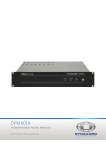
BEDIENUNGSANLEITUNG
OWNER’S MANUAL
MODE D’EMPLOI
DPM 4000
DIGITAL PROMATRIX MANAGER
WICHTIGE SICHERHEITSHINWEISE
Das Blitzsymbol innerhalb eines gleichseitigen Dreiecks soll den
Anwender auf nicht isolierte Leitungen und Kontakte im Geräteinneren hinweisen, an denen hohe Spannungen anliegen, die
im Fall einer Berührung zu lebensgefährlichen Stromschlägen
führen können.
Das Ausrufezeichen innerhalb eines gleichseitigen Dreiecks soll
den Anwender auf wichtige Bedienungs- sowie Servicehinweise
in der zum Gerät gehörenden Literatur aufmerksam machen.
1.
2.
3.
4.
5.
Lesen Sie diese Hinweise.
Heben Sie diese Hinweise auf.
Beachten Sie alle Warnungen.
Richten Sie sich nach den Anweisungen.
Betreiben Sie dieses Gerät nicht in unmittelbarer Nähe von Wasser. Stellen Sie bitte sicher, daß kein Tropf- oder
Spritzwasser ins Geräteinnere eindringen kann. Plazieren Sie keine mit Flüssigkeiten gefüllte Objekte, wie Vasen oder
Trinkgefäße, auf dem Gerät ab.
6. Verwenden Sie zum Reinigen des Gerätes ausschließlich ein trockenes Tuch.
7. Verdecken Sie keine Lüftungsschlitze. Beachten Sie bei der Installation des Gerätes stets die entsprechenden
Hinweise des Herstellers.
8. Vermeiden Sie die Installation des Gerätes in der Nähe von Heizkörpern, Wärmespeichern, Öfen oder anderer
Wärmequellen.
9. Verwenden Sie mit dem Gerät ausschließlich Zubehör/Erweiterungen, die vom Hersteller hierzu vorgesehen sind.
10. Überlassen Sie sämtliche Servicearbeiten und Reparaturen einem ausgebildeten Kundendiensttechniker.
Bringen Sie das Gerät direkt zu unserem Kundendienst, wenn es beschädigt wurde oder eine Funktionsstörung zeigt.
11. Um das Gerät komplett spannungsfrei zu schalten, muß der Netzstecker gezogen werden.
WICHTIGE SERVICEHINWEISE
ACHTUNG: Diese Servicehinweise sind ausschließlich zur Verwendung durch qualifiziertes Servicepersonal.
Um die Gefahr eines elektrischen Schlages zu vermeiden, führen Sie keine Wartungsarbeiten durch,
die nicht in der Bedienungsanleitung beschrieben sind, außer Sie sind hierfür qualifiziert.
Überlassen Sie sämtliche Servicearbeiten und Reparaturen einem ausgebildeten Kundendiensttechniker.
1. Bei Reparaturarbeiten im Gerät sind die Sicherheitsbestimmungen nach EN 60065 ( VDE 0860 ) einzuhalten.
2. Bei allen Arbeiten, bei denen das geöffnete Gerät mit Netzspannung verbunden ist und betrieben wird, ist ein Netz Trenntransformator zu verwenden.
3. Vor einem Umbau mit Nachrüstsätzen, Umschaltung der Netzspannung oder sonstigen Modifikationen ist das Gerät
stromlos zu schalten.
4. Die Mindestabstände zwischen netzspannungsführenden Teilen und berührbaren Metallteilen
(Metallgehäuse) bzw. zwischen den Netzpolen betragen 3 mm und sind unbedingt einzuhalten.
Die Mindestabstände zwischen netzspannungsführenden Teilen und Schaltungsteilen, die nicht mit dem Netz
verbunden sind (sekundär), betragen 6mm und sind unbedingt einzuhalten.
5. Spezielle Bauteile, die im Stromlaufplan mit dem Sicherheitssymbol gekennzeichnet sind, (Note) dürfen nur durch
Originalteile ersetzt werden.
6. Eigenmächtige Schaltungsänderungen dürfen nicht vorgenommen werden.
7. Die am Reparaturort gültigen Schutzbestimmungen der Berufsgenossenschaften sind einzuhalten. Hierzu gehört auch
die Beschafdes Arbeitsplatzes.
fenSAFETY COMPONENT ( MUST BE REPLACED BY ORIGINAL PART )
heit Note:
2
ACHTUNG!
1. Wegen Brandgefahr und der Möglichkeit eines elektrischen Schlages müssen die Geräte und
Module vor Feuchtigkeit geschützt werden.
2. Achten Sie darauf, daß nichts in die Geräte gesteckt wird oder mit den Modulen in Berührung kommt,
insbesondere keine Metallgegenstände. Es besteht dabei die Gefahr eines schweren
elektrischen Schlages oder einer Funktionsstörung. Im Inneren der Geräte und auf den Modulen
befinden sich keine Bauteile, die vom Benutzer gewartet werden müssen. Das Öffnen der Gehäuse und
Gestellschränke ist mit erheblichen Gefahren verbunden. Versuchen Sie niemals, auf Bauteile im Inneren
der Geräte oder Gestellschränke aus Reparatur-, Wartungs- -oder anderen Gründen
zuzugreifen.
3. Werden die Geräte oder Module starken Temperaturwechseln ausgesetzt, z. B. beim Transport von
außen in einen beheizten Raum, kann es zu Kondenswasserbildung kommen. In derartigen Fällen muß
mit der Inbetriebnahme gewartet werden, bis sich die Geräte und Module auf Raumtemperatur
erwärmt haben.
4. Stellen Sie auf gar keinen Fall irgendwelche Behälter mit Flüssigkeiten auf die Gehäuse. Sollten
Flüssigkeiten oder Gegenstände in das Innere eines Gehäuses gelangen, trennen Sie das Gerät
sofort von allen Versorgungsspannungen, und lassen Sie es von einer Servicewerkstatt überprüfen.
5. Achten Sie darauf, daß die Geräte und Module immer gut belüftet und nie dem direkten Sonnenlicht
oder übermäßiger Fremderwärmung ausgesetzt sind.
6. Setzen Sie die Geräte und Module keinesfalls übermäßiger Staubentwicklung und hoher
Luftfeuchtigkeit aus. Durch diese Umgebungsbedingungen kann ein Brand oder ein elektrischer Schlag
verursacht werden.
7. Beachten Sie, daß die angegebenen Versorgungsspannungen eingehalten werden, da andernfalls Ihre
Geräte oder Module schwer beschädigt werden können.
8. Sorgen Sie dafür, daß Netzkabel, Versorgungskabel oder sonstige Anschlußkabel nicht beschädigt und
nicht durch den Schwenkrahmen oder durch sonstige bewegliche Teile des Gestellschrankes
eingeklemmt werden können. Ein beschädigtes Kabel kann einen Brand oder einen elektrischen Schlag
verursachen.
9. Das Netzkabel des Gestellschrankes ist mit einem dreipoligen Stecker ausgestattet, um die Gefahr
eines elektrischen Schlages zu verhindern. Das Netzkabel ist nur an eine korrekt geerdete Steckdose
anzuschließen. Überkleben Sie auf keinen Fall den Erdungskontakt. Bei Verwendung eines
Verlängerungskabels muß ein dreiadriges, geerdetes Kabel eingesetzt werden. Vermeiden Sie eine
Überlastung der Wandsteckdose durch eventuell benutzte Mehrfachsteckdosen, da dies einen Brand
oder einen elektrischen Schlag verursachen kann.
10. Im DPM 4000 befindet sich eine Lithium-Batterie, um die Echtzeituhr im ausgeschalteten Zustand mit
Strom zu versorgen. Die Lebensdauer dieser Batterie beträgt ungefähr 10 Jahre. Sobald Ihre
Spannung unter einen erforderlichen Mindestwert absinkt, wird dies durch eine Meldung im
Sprechstellen-Display angezeigt. In diesem Fall müssen Sie die Batterie durch eine von EVI Audio GmbH
autorisierte Servicestelle auswechseln lassen. Auf keinen Fall sollten Sie das selbst tun!
ACHTUNG! Explosionsgefahr bei unsachgemäßem Auswechseln der Batterie. Nur durch
denselben oder einen entsprechenden, vom Hersteller empfohlenen Typ ersetzen.
Verbrauchte Batterien nach den Anweisungen des Herstellers beseitigen.
11. Für das Errichten und Betreiben von 100V-Lautsprecheranlagen ist die VDE-Bestimmung DIN VDE
0800 zu beachten. Besonders bei 100V-Lautsprecheranlagen für Alarmierungszwecke sind alle
Schutzmaßnahmen für die Bemessungsklasse 3 auszulegen.
VORSICHT!
Die Anschlußbuchsen für die Lautsprecherkreise (POWER OUTPUT) können im
Betrieb berührungsgefährliche Spannungen (>34V Spitzenwert) aufweisen. Die
angeschlossenen Lautsprecherkreise sind aus diesem Grund gemäß der oben
genannten Sicherheitsbestimmungen zu installieren.
12. Schalten Sie die Anlage erst ein, nachdem alle Verbindungen hergestellt sind. Ein- und Abstecken
von Verbindungsleitungen während des Betriebs kann Funktionsstörungen oder Beschädigung der
beteiligten Geräte zur Folge haben.
3
D igital PROM A T R IX Manager DPM 4000
Wir freuen uns, daß Sie sich für das PROMATRIX System von DYNACORD entschieden haben, und
möchten Ihnen dafür herzlich danken. Mit dem PROMATRIX System erhalten Sie ein Qualitätsprodukt,
das höchsten Anforderungen gerecht wird. Es ist ein äußerst flexibles und vielseitiges System, mit dem
Sie einfache Anlagen, aber auch beliebig komplexe Installationen aufbauen können.
Eine detaillierte Gerätebeschreibung sowie Hinweise für den Anschluß, die Konfiguration und die
Bedienung des DPM 4000 finden Sie im PROMATRIX System Benutzerhandbuch (Nr. 355 018).
Installationshinweis
Bei der Montage des Moduls und der Installation der Anschlüsse ist darauf zu achten, daß die Anforderungen der VDE 0100 und EN 60065 eingehalten werden.
Betriebshinweise
Zentraleinheit DPM 4000
Die DPM 4000 Zentraleinheit kann im Rahmen der spezifizierten Möglichkeiten und technischen Daten
dieses Produkts zur Steuerung und Überwachung von Beschallungs- und Rufanlagen im Bereich der
Gebäudeinstallation aber auch für professionelle Audiosysteme eingesetzt werden.
Die DPM 4000 Zentraleinheit ist ein kein eigenständiges Gerät. Für den Betrieb werden mindestens
benötigt:
1. Ein Netzteil (24 V / 4 A) (24 V / 12 A), vorzugsweise der DPP 4000 - Serie, je nach gefordertem
Strombedarf der Anlage.
2. Falls das Gerät mit Sprechstellen betrieben werden soll:
-
Die gewünschte Anzahl von Sprechstellen der DPC 4000 - Serie (max. 16).
-
Die zugehörigen Verbindungskabel.
3. Falls der Audioteil des Gerätes verwendet wird:
-
Leistungsverstärker, vorzugsweise der DPA 4000 - Serie, inkl. Verkabelung
-
Lautsprecher inkl. Verkabelung
4. Falls die interne Echtzeituhr auf das DCF77 - Zeitsignal synchronisiert werden soll:
-
Eine aktive DCF77 - Empfangsantenne (NRS 90193) inkl. Verkabelung
Dieses Austattungsmerkmal ist nur in Regionen nutzbar, in denen das DCF77 - Signal mit einer
ausreichenden Feldstärke empfangen werden kann.
5. Falls Nebenuhren angesteuert werden sollen:
-
Die gewünschte Anzahl von Nebenuhren (max. 40) inkl. Verkabelung
Für die Konfiguration und Inbetriebnahme wird außerdem ein PC mit folgender Ausstattung benötigt:
- PC Computersystem mit Pentiumprozessor (mind. 80486-Prozessor, 90 MHz) und Windows 95
- 16 MB Arbeitsspeicher (RAM)
- 1 Festplatte mit mind. 5 MB freier Festplattenkapazität
- 1 Diskettenlaufwerk 3 ½ Zoll, 1.44 MB
- 1 Maus
- 1 Monitor (mind. 800 x 600 Pixel Auflösung) mit VGA-Grafikkarte, 256 Farben
- 1 Serielle Schnittstelle RS-232 mit Schnittstellenkabel
- Konfigurationssoftware PROMATRIX Designer
Alle Anschlußkabel bzw. Stecker, Kupplungen oder Adapter zur Herstellung der erforderlichen Verkabelung sind von EVI Audio GmbH erhältlich. Sämtliches Zubehör mit Bestellnummern finden Sie in den
jeweiligen Bedienungsanleitungen oder in der ELA Preisliste.
4
Aufstellungsort
Die Geräte sind ausschließlich für den Einbau in einen 19"- Gestellschrank vorgesehen. Module können auch in einen geeigneten Wandanschlußkasten montiert werden. Bei der Aufstellung müssen die
Sicherheitshinweise in Kapital 2.1 beachtet werden.
Insbesondere sind folgende Umgebungsbedingungen einzuhalten:
-
Die Umgebungstemperatur am Aufstellungsort - auch im Inneren des Gestellschrankes - darf nicht
höher als 40°C sein. Gegebenenfalls muß der Gestellschrank zwangsbelüftet oder klimatisiert werden.
Starke Wärmequellen wie z. B. Endstufen, die vor allem unterhalb des Gerätes montiert sind, können
die Umgebungstemperatur des Gerätes unzulässig erhöhen, obwohl die Durchschnittstemperatur in
dem Gestellschrank unter 40°C liegt.
-
Der Aufstellungsort darf keiner übermäßigen Staub- und Feuchtigkeitsentwicklung ausgesetzt sein.
-
Die Geräte sollte keiner direkten Sonneneinstrahlung ausgesetzt werden.
-
Die rückseitig angebrachten Anschlüsse müssen vor direkten Zugriff während des Betriebes
geschützt sein, da diese zum Teil lebensgefährliche Spannung führen können.
-
Die Lüftungsschlitze dürfen nicht durch andere Einbauten abgedeckt werden. Zu diesem Zweck ist es
sinnvoll eine 1 HE Lüftungsblende oberhalb des betroffenen Gerätes vorzusehen.
-
Der Aufstellungsort muß vor Vibrationen geschützt sein.
Garantieausschlüsse
Für Schäden, Störungen oder Beeinträchtigung der Leistungsmerkmale, die aufgrund der folgenden
Ursachen entstehen, kann keine Garantie übernommen werden.
-Unsachgemäße oder unangemessene Wartung durch den Kunden
-Nicht genehmigte Änderungen
-Betrieb außerhalb der Umgebungsbedingungen für dieses Produkt
-Betrieb außerhalb der elektrischen Spezifikationen
-Unsachgemäße Installation
-Transportschaden aufgrund unsachgemäßer Verpackung durch den Kunden
Reparaturen, Austausch leerer Batterien, Veränderungen und Erweiterungen dürfen ausschließlich durch
die Firma EVI Audio GmbH oder eine von ihr autorisierten Person oder Stelle ausgeführt werden.
5
Frontseite
DPM 4000 Frontansicht
Auf der Frontseite des DPM 4000 befinden sich folgende Bedien- und Anzeigeelemente:
1. LED DCF 77
Diese LED zeigt den Betriebszustand des DCF 77 Funkuhrsignalempfängers an. Die verschiedenen
Zustände bedeuten:
LED Zustand
Bedeutung
Aus
Es ist kein Funkuhrsignal vorhanden oder keine Funkuhrantenne
angeschlossen. Die Systemuhr läuft quarzgesteuert.
Ein
Das Funkuhrsignal ist in Ordnung.
Die Systemuhr ist DCF 77 synchronisiert.
Blinken, Sekundentakt
Ein Funkuhrsignal ist vorhanden und die Systemuhr wird aufsynchronisiert.
Dieser Vorgang kann bis zu 2 Minuten dauern. Nach erfolgreicher
Synchronisation leuchtet die DCF 77 LED dauernd.
Blinken, schnell
Ein Funkuhrsignal ist zwar vorhanden aber gestört. Die Funkuhrantenne
sollte entweder neu ausgerichtet oder an einem anderen Aufstellungsort mit besserem Empfang montiert
werden.
2. LED READY
Diese LED signalisiert den Betriebszustand des PROMATRIX Systems. Nach dem Einschalten blinkt
READY während des Hochfahrens der Anlage. Das kann je nach Anlagenkomplexität einige Sekunden
dauern. Nach erfolgreicher Initialisierung leuchtet die LED und zeigt damit Betriebsbereitschaft an. Bei
Störungen sowohl im DPM 4000 als auch in angeschlossenen Komponenten geht die LED aus und weist
so auf Fehler im System hin.
3. LED POWER
Diese LED leuchtet, sobald die Spannungsversorgung des DPM 4000 (24 V =, Netzteil oder Batterie)
angeschlossen ist. Die LED ist aus, wenn der DPM 4000 von der Spannungsversorgung getrennt ist, oder
wenn die Spannungsversorgung ausgeschaltet oder ausgefallen ist.
4. LED FAULT
Diese LED leuchtet während eines Resets oder bei einem Watchdog-Fehler im DPM 4000 intern.
Außerdem werden damit Fehler in externen Anlagenteilen (Endstufen, Sprechstellen, Relaiskarten,...)
angezeigt. Die LED ist mit dem READY-Relais an der Geräterückseite gekoppelt, womit ein Fehlverhalten
der Anlage auch nach außen gemeldet werden kann.
6
OWNER’S MANUAL
DPM 4000
DIGITAL PROMATRIX MANAGER
7
IMPORTANT SAFETY INSTRUCTIONS
The lightning flash with arrowhead symbol, within an equilateral
triangle is intended to alert the user to the presence of uninsulated
“dangerous voltage” within the product’s enclosure that may be of
sufficient magnitude to constitute a risk of electric shock to persons.
The exclamation point within an equilateral triangle is intended to
alert the user to the presence of important operating and maintance
(servicing) instructions in the literature accompanying the appliance.
1.
2.
3.
4.
5.
Read these instructions.
Keep these instructions.
Heed all warnings.
Follow all instructions.
Do not use this apparatus near water. Do not expose this apparatus to dripping or splashing and ensure that no objects
filled with liquids, such as vases, ase placed on this apparatus.
6. Clean only with a dry cloth.
7. Do not block any of the ventilation openings. Install in accordance with the manufactures instructions.
8. Do not install near any heat sources such as radiators, heat registers, stoves, or other apparatus that produce heat.
9. Only use attachments/accessories specified by the manufacturer.
10. Refer all servicing to qualified service personnel. Servicing is required when the apparatus has been damaged in any
way, such as power-supply cord or plug is damaged, liquid has been spilled or objects have fallen into the apparatus,
the apparatus has been exposed to rain or moisture, does not operate normally, or has been dropped.
11. To completely disconnect mains power from this apparatus, the power supply cord must be unplugged.
For US and CANADA only:
Do not defeat the safety purpose of the grounding-type plug. A grounding type plug has two blades and a third grounding prong.
The wide blade or the third prong are provided for your safety. When the provided plug does not fit into your outlet, consult an
electrican for replacement of the absolete outlet.
IMPORTANT SERVICE INSTRUCTIONS
CAUTION:
1.
2.
3.
4.
5.
6.
7.
8.
These servicing instructions are for use by qualified personnel only. To reduce the risk of
electric shock, do not perform any servicing other than that contained in the Operating
Instructions unless you are qualified to do so. Refer all servicing to qualified service personnel.
Security regulations as stated in the EN 60065 (VDE 0860 / IEC 65) and the CSA E65 - 94 have to be obeyed when
servicing the appliance.
Use of a mains separator transformer is mandatory during maintenance while the appliance is opened, needs to be
operated and is connected to the mains
Switch off the power before retrofitting any extensions, changing the mains voltage or the output voltage.
The minimum distance between parts carrying mains voltage and any accessible metal piece (metal enclosure),
respectively between the mains poles has to be 3 mm and needs to be minded at all times.
The minimum distance between parts carrying mains voltage and any switches or breakers that are not connected
to the mains (secondary parts) has to be 6 mm and needs to be minded at all times.
Replacing special components that are marked in the circuit diagram using the security symbol (Note) is only permissible
when using original parts.
Altering the circuitry without prior consent or advice is not legitimate.
Any work security regulations that are applicable at the location where the appliance is being serviced have to be strictly
obeyed. This applies also to any regulations about the work place itself.
All instructions concerning the handling of MOS - circuits have to be observed.
Note:
SAFETY COMPONENT (HAS TO BE REPLACED WITH ORIGINAL PART ONLY)
8
CAUTION!
1. To prevent the risk of fire and shock hazard, all appliances and modules have to be protected from
humidity and water.
2. Make sure that no alien objects enter the appliances or get in contact with the modules - especially
no metal parts - since this would cause dangerous electric shock and/or malfunctioning. There are no
user-serviceable parts inside the appliances or on the modules. Opening appliance enclosures and/or
rack shelf systems can lead to dangerous shock hazard. Leave installation, servicing, maintenance,
and any other works on the appliances or the rack shelf system to qualified service personnel only.
3. When appliances or modules are exposed to extreme temperature changes, i. e. after transportation
from the outside into a warm environment, condensation can occur. If so, it is necessary to wait before
use until the devices gained room temperature.
4. Under no circumstance place any liquid containing cans, glasses, mugs, etc. on top of the enclosure.
In case any liquid or foreign obstacles enter the appliance’s enclosure, immediately unplug the device
from any power source (mains and/or battery) and have it serviced.
5. Make sure that the appliances/modules are always provided with sufficient ventilation. Do not expose
the devices to direct sunlight or any other heat-radiating source.
6. Do not expose the appliances/modules to extreme dust or humidity. Operating the system under
environmental conditions like these can lead to severe damage through fire or cause bodily harm to
the operator.
7. Make sure that the stated mains voltage is in accordance to the specifications of your mains supplier.
Mismatching can cause severe damage to the entire system installation.
8. Make sure that the mains cord and/or any other cabling is not damaged or is getting jammed by the
turning frame or any other moving part of the rack shelf. Damaged cables can lead to fire hazard
and/or can be the cause for electric shock.
9. The rack shelf installation’s mains cord is supplied with a 3-pole plug to eliminate the risk of electric
shock. It should only be connected to a correctly grounded wall outlet. Do not insulate the ground
contact in any way. When using an extension cord, always use a 3-pole grounded cable. When using
multi-outlets for distributing, make sure that the wall outlet’s capacity is not exceeded, since this could
lead to fire hazard and/or can be the cause for electric shock.
10. The DPM 4000 contains a lithium-type battery to provide the internal clock with power when the
appliance is switched off. The lifetime of this battery-type spans approximately 10 years. When the
battery’s voltage drops below a certain minimum, an according message appears on the display of the
paging station. In this case, the battery has to be exchanged by an EVI Audio GmbH authorized
service technician. Under no circumstance try to exchange the battery yourself!
CAUTION! There is a severe risk of explosion when incorrectly exchanging the battery. Only
replace with the same type of battery or one especially recommended by the
manufacturer. For environmental awareness: Take care of used batteries
according to the manufacturer’s advice.
11. The VDE regulation DIN VDE 0800 applies to any installing or operation of 100V sound
reinforcement systems. Especially with 100V alert PA-systems all safety class 3 regulations apply.
CAUTION! It is possible for the loudspeaker group connectors (POWER OUTPUT) to carry
shock-hazard output voltages (>34V peak value) during operation. Thus, the
connected loudspeaker groups have to be installed in accordance to security
standards and regulations as stated above.
12. Make all connections before operating the system. Connecting/disconnecting cables during
operation can cause malfunctioning or damage to the correspondent appliances.
9
Digital PROMATRIX Manager DPM 4000
Thank you for choosing the DYNACORD PROMATRIX System. With the PROMATRIX System you
purchased a high-quality product which is going to satisfy your highest demands. This extraordinarily
flexible and versatile system allows configuring small or rather complex installations of any size.
A complete and detailed description of the system including instructions on how to install, configure, and
operate the DPM 4000 is provided in the PROMATRIX System handbook (order No. 355 018).
Installation Note
Mounting appliances or modules and establishing connections has to be in accordance to V DE 0100 and
EN 60065 regulations.
Operation Note
Central Unit DPM 4000
According to its specified capabilities and specifications, the DPM 4000 central unit can be used for
controlling and monitoring permanently installed PA- and paging systems. It can also be used for
professional audio system applications.
The DPM 4000 central unit is no stand-alone device. For its operation at least the following is necessary:
1. A power supply unit (24 V / 4 A) (24 V / 12 A), preferably a DPP 4000 Series model; depending on
the individual power consumption of the entire system
2. When the installation includes paging stations:
-
the desired amount of DPC 4000 Series paging station units (max. 16)
-
the necessary cords and cables
3. When utilizing unit’s audio section:
-
power amps, preferably of the DPA 4000 Series, including cabling
-
loudspeaker systems, including cabling
4. When DCF77-synchronized operation of the real-time system clock is desired:
-
an active DCF77-antenna (NRS 90193), including cabling
Using this feature is only possible in areas where the reception-quality of the DCF77-signal is sufficient.
5. When synchronizing slave clocks to the system clock:
-
the desired amount of slave clocks (max. 40), including cabling
A personal computer with the following features is needed for configuring and operating the DPM 4000:
- PC computer system with pentium processor (at least 80486 CPU, 90 MHz) and Windows 95
- 16 MB of RAM
- at least 5 MB of free hard disk space
- 1 3 1/2 “ floppy drive, 1.44 MB
- 1 mouse
- 1 monitor (with a resolution of at least 800 x 600 pixels) with VGA-graphic board, 256 color mode
- 1 RS-232 serial port with serial cable
- PROMATRIX Designer configuration software
All necessary connection cords, plugs, connectors, and adapters are available from EVI Audio GmbH.
For all available accessories including order-numbers, please refer to the correspondent owner’s manuals
or the EVI Audio PA-system price list.
10
Installation Location
The appliances are exclusively meant for the installation in 19" rack shelf systems while the modules can
also be mounted in an appropriate wall junction box. When installing the system, the safety regulations
of chapter 2.1 do apply.
It is particularly important that the following environmental conditions are provided:
-
ambient temperature at the installation site and including inside the rack shelf system is not to
exceed 40° C. If necessary, the rack shelf system has to be supplied with forced ventilation or air
conditioning.
Heat sources like power amplifiers, etc. - especially when they are mounted underneath the
appliance - can increase the ambient temperature to an exceeding degree, although the average
temperature within the rack shelf system stays below 40° C.
-
The installation site should not suffer from extreme dust and moisture.
-
Direct sunlight should be avoided.
-
During operation, rear connectors have to be covered, since they partly conduct voltages that could
endanger your life.
-
Ventilation louvres are not to be covered by any obstacles. Therefore, it is reasonable to install a
1 HU ventilation blind above the correspondent appliance.
-
The installation site should not be subject to vibration.
Excluded From Warranty
Damages, malfunction, or obstruction of certain performance features resulting from the following causes
are excluded from the warranty.
-improper or erroneous maintenance by the customer
-changes or alterations without written consent
-operation outside of the environmental conditions specified for this product
-operation outside of electrical specifications
-improper installation
-damage during transportation because of improper packaging by the customer
Repair, exchange of used batteries, altering and extending the product is only admissible when EVI Audio
GmbH or one of its authorized service centers or maintenance technicians carries it out.
11
Front View
DPM 4000 Front View
The front panel of the DPM 4000 provides the following controls and indicators:
1. LED DCF 77
This LED indicates the operational status of the DCF 77 radio-control signal-receiver. The meaning of
individual indications is explained in the following table:
LED Indication
Meaning
OFF
No radio control signal detected or no DCF 77 antenna connected.
The system clock operates quartz-synchronized.
ON
The radio control signal is received. The system clock is synchronized
to the DCF 77 signal.
Blinking,
with a frequency of 1 Hz
The radio control signal is present and the system clock is being
synchronized. This procedure can take up to 2 minutes.
After synchronization is complete, the DCF 77 LED lights continuously.
Blinking, fast
The radio control signal is detected but its reception is jammed.
Readjusting the DCF 77 antenna or choosing a location with proper
reception should solve the problem.
2. LED READY
This LED indicates the operation mode of the PROMATRIX System. After switching the power on, the
READY LED blinks during the system is booted. Depending on the complexity of the installation this can
take several seconds. After successful initialization, the LED lights, signaling that the system is ready for
operation. Whenever erroneous operation - either in the DPM 4000 or in one of the connected components
- is detected, the LED goes out, indicating that a system malfunction occurred.
3. LED POWER
This LED lights as soon as the DPM 4000 is connected to a power source (24 V =, power supply unit or
battery). The LED is not lit when the DPM 4000’s power supply is disconnected, switched off or fails.
4. LED FAULT
This LED lights during a reset or when a watchdog error is detected within the DPM 4000. It also indicates
malfunctioning of external system components (power amplifiers, paging stations, relay cards...). The
LED is connected to the READY relay on the rear of the appliance, which allows remote indication of
system errors.
12
MODE D’EMPLOI
DPM 4000
DIGITAL PROMATRIX MANAGER
13
IMPORTANTES INFORMATIONS DE SÉCURITÉ
Le symbole «éclair» à l’intérieur d’un triangle signale à
l’utilisateur la présence dans l’appareil de câbles et de
contacts qui ne sont pas isolés, dans lesquels circule un
courant électrique à haute tension, et qu’on ne doit en
aucun cas toucher afin d’éviter de recevoir une décharge
électrique qui pourrait être mortelle.
Le symbole «point d’exclamation» à l’intérieur d’un triangle signale à l’utilisateur les consignes importantes
concernant la maintenance et l’emploi de l’appareil, il vous
invite à lire le mode d’emploi accompagnant cet appareil.
1.
2.
3.
4.
5.
Lisez ces instructions.
Conservez ces instructions.
Tenez compte des avertissements.
Respectez toutes les instructions.
Ne pas utiliser cet appareil près d’un point d’eau. Ne pas exposer cet appareil à la pluie ni aux éclaboussures et
veiller à ce qu’aucun récipient, tel que vase, verre, etc., ne soit posé sur cet appareil.
6. Nettoyer uniquement à l’aide d’un chiffon sec.
7. Ne bloquez aucun des orifices de ventilation. Installez-le en respectant les instructions du fabricant.
8. Ne l’installez pas près de sources de chaleur telles que radiateurs, poêles, ou autres appareils produisant de la
chaleur.
9. Utilisez uniquement les accessoires spécifiés par le fabricant.
10. Adressez-vous toujours à un personnel qualifié pour toutes les réparations. Une révision est nécessair lorsque
l’appareil a été endommagé d’une manière quelconque : sa prise ou son cordon d’alimentation sont abimés,
du liquide a été renversé ou des objets sont tombés à l‘intérieur, l’appareil a été exposé à la pluie ou à l’humidité,
son fonctionnement est anormal ou il a subit une chute.
11. Pour déconnecter complètement cet appareil du secteur, il faut débrancher le cordon d’alimentation.
INSTRUCTIONS DE RÉPARATION IMPORTANTES
ATTENTION :
Ces instructions de maintenance s’adressent uniquement à des techniciens
qualifiés. Pour réduire le risque d’électrocution, n’effectuez aucune opération de
maintenance autre que celles contenues dans les instructions d’utilisation, à moins
d’être qualifié pour le faire. Confiez toutes ces interventions à un personnel qualifié.
1. Les règles de sécurité telles qu’elles sont spécifiées par les directives EN 60065 (VDE 0860 /
IEC 65) et CSA E65 - 94 doivent être observées lors de la réparation de l’appareil.
2. L’usage d’un transformateur d’isolation est obligatoire pendant la maintenance lorsque l’appareil est ouvert, qu’il doit
fonctionner et est branché sur le secteur.
3. Mettez hors tension avant de brancher toute extension, changer la tension secteur ou celle de sortie en fonction.
4. La distance minimum entre les éléments sous tension secteur et toute pièce de métal accessible (boîtier métallique),
doit être de 3 mm entre phase. Ceci doit être respecté en permanence. La distance minimum entre les éléments
sous tension secteur et tout commutateur ou interrupteur non connecté au secteur (éléments secondaires) doit
être de 6 mm. Ceci doit être respecté en permanence.
5. Le remplacement de composants spéciaux qui sont marqués d’un symbole de sécurité (Remarque) sur le schéma
de principe n’est autorisé qu’en utilisant des pièces d’origine.
6. La modification des circuits sans autorisation ou avis préalable n’est pas permise.
7. Toutes les règlementations concernant la sécurité du travail en vigueur dans le pays où l’appareil est réparé doivent
être strictement observées. Ceci s’applique également aux règlementations concernant le lieu de travail lui-même.
8. Toutes les instructions concernant la manipulation de circuits MOS doivent être respectées.
REMARQUE:
COMPOSANT DE SÉCURITÉ (NE DOIT ÊTRE REMPLACÉ QUE PART
UNE PIÈCE D’ORIGINE)
14
ATTENTION!
1. Pour éviter tout risque d’incendie et d’électrocution, tous les appareils et modules doivent être
protégés contre l’humidité et l’eau.
2. Veillez à ce qu’aucun corps étranger ne pénètre dans les appareils ou ne soit en contact avec les
modules, surtout des objets métalliques, ceci pourrait provoquer une électrocution dangereuse ou des
dysfonctionnements. Il n’y a aucun élément réparable par l’utilisateur à l’intérieur de ces appareils
ni dans les modules. Le fait d’ouvrir les boîtiers des appareils et/ou les armoires de racks peut aussi
provoquer une électrocution. Toutes les interventions d’installation, de réparation, de maintenance, ou
autre sur les appareils ou les armoires de racks ne doivent être effectuées que par un personnel qualifié.
3. Lorsque les appareils ou les modules sont exposés à de brusques changements de température, par
exemple après un transport depuis l’extérieur dans un environnement chaud, de la condensation peut se
former. Dans ce cas, il est nécessaire d’attendre avant d’utiliser les appareils, que ceux-ci aient pris la
température de la pièce.
4. Ne jamais placer de récipients contenant du liquide, verres, vases, etc. sur les appareils. Si du
liquide ou des corps étrangers ont été introduits par mégarde dans le boîtier de l’appareil, il faut le
débrancher immédiatement (secteur et/ou batterie) et le faire réviser.
5. Vérifiez que les appareils/modules disposent toujours d’une ventilation suffisante. N’exposez pas les
appareils aux rayons directs du soleil ni à toute autre source de chauffage.
6. N’exposez pas les appareils/modules à une humidité extrême ou à la poussière. Faire fonctionner le
système dans de telles conditions d’environnement peut provoquer de sérieux dommages (incendie) ou
des blessures.
7. Vérifier que la tension secteur locale correspond bien aux caractéristiques de votre alimentation
secteur. Une tension inadéquate peut provoquer des dommages à l’ensemble du système.
8. Vérifier que le cordon d’alimentation ou tout autre câble ne soit ni endommagé, ni coincé par les
parties mobiles de l’armoire de racks. Des câbles endommagés peuvent provoquer des risques
d’incendie ou d’électrocution.
9. Le cordon d’alimentation de l’armoire de racks est muni d’une prise à trois fiches, ceci pour éliminer
tout risque d’électrocution. Elle ne doit être branchée que dans une prise secteur avec mise à la terre.
Ne jamais isoler le contact avec la terre. Lorsque vous utilisez une rallonge, utilisez toujours un câble
muni d’une prise à 3 fiches. Lors de l’utilisation de prises multiples, veillez à ce que la capacité fournie
par la prise secteur ne soit pas dépassée, car cela pourrait provoquer des risques d’incendie ou
d’électrocution.
10. Le DPM 4000 contient une pile au lithium qui alimente l’horloge interne lorsque l’appareil est hors
tension. La durée de vie de ce type de pile est d’approximativement 10 ans. Lorsque la tension de la
pile tombe en dessous du minimum fixé, un message d’alerte apparaît à l’écran de la station d’appel.
Dans ce cas, il faut faire remplacer la pile par un service technique agréé EVI Audio GmbH. Il ne faut
en aucun cas essayer de remplacer la pile vous-même !
ATTENTION ! Il y a un risque d’explosion important si la pile n’est pas remplacée correctement.
Ne la remplacer que par une pile du même type ou une spécialement recommandée
par le fabricant. Dans un souci de protection de l’environnement : Jeter les piles
usagées en respectant les conseils du fabricant.
11.La réglementation VDE DIN VDE 0800 s’applique à toute installation ou manipulation de systèmes de
sonorisation de 100V. Par contre avec les systèmes de sonorisation de sécurité de 100V, c’est la
réglementation concernant les appareils de sécurité de Classe 3 qui s’applique.
ATTENTION ! Il est possible que les connecteurs de groupes de haut-parleurs (POWER OUTPUT)
véhiculent des tensions de sortie élevées (valeurs de crête >34V) pendant leur
fonctionnement. C’est pourquoi, les groupes de haut-parleurs connectés doivent être
installés en respectant les standards de sécurité et la réglementation comme
mentionné ci-dessus.
12.Effectuer toutes les connexions avant de faire fonctionner le système. Connecter/déconnecter les câbles
lors du fonctionnement peut provoquer des pannes ou endommager les appareils concernés.
15
PROMATRIX Manager numérique DPM 4000
Félicitations pour avoir choisi le système PROMATRIX DYNACORD. En choisissant le système PROMATRIX vous avez acquis un produit de haute qualité qui satisfera toutes vos exigences. Ce système
extraordinairement souple et versatile permet de configurer des installations de toutes tailles, de la plus
petite à la plus complexe.
Une description complète et détaillée du système incluant les instructions d’installation, de configuration,
et de fonctionnement du DPM 4000 se trouvent dans le mode d’emploi du système PROMATRIX (n° de
commande 355 018).
Remarque concernant l’Installation
Le montage des appareils ou des modules ainsi que la réalisation des connexions doivent
satisfaire aux réglementations VDE 0100 et EN 60065.
Remarque concernant le fonctionnement
Unité centrale DPM 4000
En fonction des possibilités et des caractéristiques mentionnées, l’unité centrale du DPM 4000 peut être
utilisée pour contrôler et surveiller en permanence des systèmes de sonorisation et d’appel déjà installés.
Il peut également être utilisé dans le cadre d’applications audio professionnelles.
L’unité centrale du DPM 4000 n’est pas un appareil indépendant. Pour fonctionner, les éléments suivants
sont nécessaires :
1. Une alimentation (24 V / 4 A) (24 V / 12 A), de préférence un modèle de la gamme DPP 4000; en
fonction de la consommation électrique globale du système
2. Lorsque l’installation comprend des stations d’appel :
-
Le nombre d’unités de stations d’appel DPC 4000 désiré (max. 16)
-
Les cordons et câbles nécessaires
3. Lors de l’utilisation de la section audio de l’unité :
-
Amplificateurs de puissance, de préférence de la gamme DPA 4000, avec les câbles nécessaires
-
Haut-parleurs, avec câbles
4. Lorsqu’un fonctionnement synchronisé DCF77 de l’horloge système temps réel est désiré :
-
Une antenne active DCF7 (NRS 90193), avec câbles
L’utilisation de cette fonction n’est possible que dans les zones dont la qualité de réception du signal
DCF77 est suffisante.
5. Lors de la synchronisation d’horloges esclaves à l’horloge système :
-
Le nombre voulu d’horloges esclaves (max. 40), avec câbles
Un ordinateur personnel ayant les caractéristiques suivantes est nécessaire pour configurer et faire
fonctionner le DPM 4000 :
- Ordinateur PC avec processeur Pentium (au moins une CPU 80486, 90 MHz) et Windows 95
- 16 Mo de RAM
- Au moins 5 Mo d’espace libre sur le disque dur
- 1 lecteur de disquette 3 1/2", 1.44 Mo
- 1 souris
- 1 moniteur (ayant une résolution d’au moins 800 x 600 pixels) avec cartegraphique VGA, mode
256 couleurs
- 1 port série RS-232 avec câble série
- Logiciel de configuration PROMATRIX Designer
Tous les cordons de connexion, prises, connecteurs, et adapteurs nécessaires sont disponibles auprès
de EVI Audio GmbH. Pour commander les accessoires ayant un numéro de commande, veuillez vous
reporter aux modes d’emploi correspondants ou à la liste des prix des systèmes de sonorisation EVI
Audio.
16
Installation : Emplacement
Les appareils sont exclusivement destinés à une installation dans une armoire de rack 19" alors que les
modules peuvent également être montés dans des boîtiers de raccordement muraux. Lors de l’installation
du système, les règles de sécurité énoncées au chapitre 2.1 doivent être appliquées.
Il est particulièrement important que les conditions d’environnement suivantes soient respectées :
-
la température ambiante du lieu d’installation et à l’intérieur de l’armoire de racks ne doit pas
dépasser 40° C. Si nécessaire, l’armoire de racks doit être équipée d’une ventilation forcée ou de l’air
conditionné.
Des appareils produisant de la chaleur, tels que les amplis de puissance, etc - surtout s’ils se trouvent
sous l’appareil - peuvent faire monter excessivement la température ambiante, la température
à l’intérieur de l’armoire de racks devant restée inférieure à 40° C.
-
Le lieu d’installation ne doit pas être soumis à une humidité extrême ni à la poussière.
-
Éviter l’exposition directe aux rayons du soleil.
-
En cours de fonctionnement, les connecteurs arrière doivent être recouverts, car ils conduisent
partiellement des tensions pouvant être dangereuses.
-
Les ouïes de ventilation ne doivent jamais être obstruées. Il vaut mieux laisser une hauteur de 1 HU
afin de permettre la ventilation au-dessus de l’appareil.
-
Le lieu d’installation ne doit pas être sujet à des vibrations.
Sont exclus de la garantie :
Les dommages, dysfonctionnements, ou défaillance de certaines fonctions résultant des causes suivantes sont exclus de la garantie.
-
Maintenance inadaptée ou incorrecte effectuée par le client
-
Changements ou altérations sans consentement écrit
-
Fonctionnement en dehors des conditions d’environnement spécifiées pour ce produit
-
Fonctionnement en dehors des normes électriques
-
Installation incorrecte
-
Dommages provoqués durant le transport dus à un emballage insuffisant effectué par le client
Les réparations, remplacement de la pile usagée, modification et extension du produit ne sont
permises que s’ils sont réalisés par un service après-vente agréé EVI Audio GmbH ou par des
techniciens de maintenance agréés.
17
Vue de la face avant
Face avant du DPM 4000
La face avant du DPM 4000 dispose des contrôles et témoins suivants :
1. LED DCF 77
Ce témoin à LED indique le mode de fonctionnement du récepteur de signal de contrôle radio DCF 77.
La signification des différentes indications est expliquée dans le tableau suivant :
Indication des LED
Signification
OFF
Aucun signal de contrôle radio détecté ou aucune antenne DCF 77 connectée. L’horloge
système fonctionne en étant synchronisée par quartz.
ON
Le signal de contrôle radio est reçu. L’horloge système est synchronisée au signal DCF
77.
Clignotant, à une fréquence de 1 Hz
Le signal de contrôle radio est présent et l’horloge système est synchronisée. Cette
procédure peut prendre environ 2 minutes. Une fois la synchronisation obtenue, la LED
DCF 77 s’allume en continu.
Clignotant, rapide
Le signal de contrôle radio est détecté mais sa réception est faible. Réajuster l’antenne
DCF 77 ou choisissez un autre endroit où la réception est meilleure afin de résoudre le
problème.
2. LED READY
Cette LED indique le mode de fonctionnement du système PROMATRIX. Après mise sous tension, la
LED READY clignote pendant le démarrage du système. En fonction de la complexité de l’installation
cela peut prendre plusieurs secondes. Une fois l’initialisation terminée, cette LED s’allume, indiquant que
le système est prêt à fonctionner. A chaque fois qu’une opération erronée - que ce soit sur le DPM 4000
ou sur un des composants connectés - est détectée, cette LED s’éteint, indiquant qu’un dysfonctionnement du système s’est produit.
3. LED POWER
Cette LED s’allume dès que le DPM 4000 est connecté à une source de courant (24 V =, alimentation ou
batterie). Cette LED n’est pas allumée lorsque l’alimentation du DPM 4000 est débranchée, éteinte ou
en panne.
4. LED FAULT
Cette LED s’allume lors d’une réinitialisation (Reset) ou lorsqu’une erreur est détectée par le système de
surveillance à l’intérieur du DPM 4000. Elle indique également un dysfonctionnement d’un des composants externes du système (amplificateurs de puissance, stations d’appel, cartes relais...). Cette LED est
reliée au relai READY à l’arrière de l’appareil, ce qui permet l’indication à distance des erreurs système.
18
Notizen/Notes
19
GARANTIE
WARRANTY
GARANTIE
Das Werk leistet Garantie für
alle nachweisbaren Materialund Fertigungsfehler für die
Dauer von 36 Monaten ab Verkauf.
Garantieleistungen werden nur
dann anerkannt, wenn gültige, d.h. vollständig ausgefüllte
Garantieunterlagen vorliegen.
Von der Garantie ausgenommen sind alle Schäden, die
durch falsche oder unsachgemäße Bedienung verursacht
werden. Bei Fremdeingriffen
oder eigenmächtigen Änderungen erlischt jeder Garantie- anspruch.
The manufacturer’s warranty
covers all substantial defects in
materials and workmanship for a
period of 36 months from the
date of purchase.
Liability claims are accepted solely, when a valid – correctly and
completely filled out – Warranty
Registration form is presented
by the original owner of the product. The warranty does not cover damage that results from
improper or inadequate treatment or maintenance. In case of
alteration or unauthorized repairs, the warranty is automatically terminated.
La garantie constructeur couvre
tous les défauts matériels et de
main d’œuvre pour une période
de 36 mois à compter de la date
d’achat.
La garantie ne sera reconnue
que si la Carte de Garantie, correctement et complètement
remplie, est présentée par
l’acheteur d’origine du produit.
Les dommages dus à un mauvais maniement de l’appareil, à
un traitement ou une maintenance incorrects ou inadéquats ne
sont pas garantis. Toute modification ou intervention effectuée
par une personne non qualifiée
entraîne la résiliation automatique de la garantie.
GmbH • Hirschberger Ring 45 • 94315 Straubing •Telefon (09421) 706-0 •Telefax (09421) 706-265
Änderungen vorbehalten. Subject to change without prior notice.
Printed in Germany 15. 09. 2000 /359 723
Internet: http:// www.dynacord.de