1
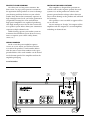
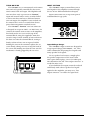
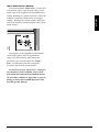
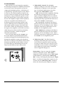
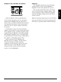
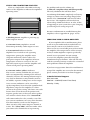
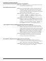
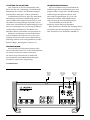
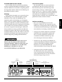
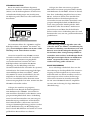
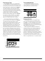
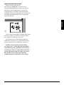
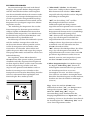
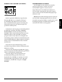
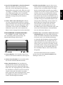
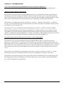
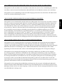
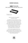
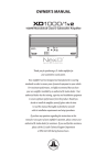
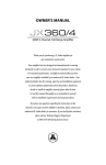
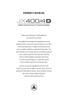
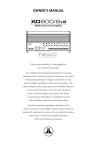
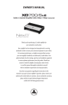
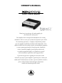
owner’s manual
200W 2-Channel Amplifier
Thank you for purchasing a JL Audio amplifier for
your automotive sound system.
Your amplifier has been designed and manufactured to exacting
standards in order to ensure years of musical enjoyment in your vehicle.
For maximum performance, we highly recommend that you have
your new amplifier installed by an authorized JL Audio dealer. Your
authorized dealer has the training, expertise and installation equipment
to ensure optimum performance from this product. Should you
decide to install the amplifier yourself, please take the time
to read this manual thoroughly so as to familiarize yourself
with its installation requirements and setup procedures.
If you have any questions regarding the instructions in this
manual or any aspect of your amplifier’s operation, please contact your
authorized JL Audio dealer for assistance. If you need further assistance,
please call the JL Audio Technical Support Department
at (954) 443-1100 during business hours.
Protect Your Hearing!
We value you as a long-term customer. For
that reason, we urge you to practice restraint in
the operation of this product so as not to damage
your hearing and that of others in your vehicle.
Studies have shown that continuous exposure to
high sound pressure levels can lead to permanent
(irreparable) hearing loss. This and all other
high-power amplifiers are capable of producing
such high sound pressure levels when connected
to a speaker system. Please limit your continuous
exposure to high volume levels.
While driving, operate your audio system in
a manner that still allows you to hear necessary
noises to operate your vehicle safely (horns,
sirens, etc.).
Installation Applications
This amplifier is designed for operation in
vehicles with 12 volt, negative-ground electrical
systems. Use of this product in vehicles with
positive ground and/or voltages other than 12V
may result in damage to the product and will void
the warranty.
This product is not certified or approved for
use in aircraft.
Do not attempt to “bridge” the outputs of this
amplifier with the outputs of a second amplifier,
including an identical one.
Serial Number
In the event that your amplifier requires
service or is ever stolen, you will need to have
a record of the product’s serial number. Please
take the time to enter that number in the space
provided below. The serial number can be found
on the bottom panel of the amplifier and on the
amplifier packaging.
Serial Number:
Status
LED
(pg. 11)
2 | JL Audio - XD200/2 Owner’s Manual
Ch. 1 & 2 Filter
Ch. 1 & 2
Frequency
Filter Mode
Selector
Selection
(pg. 8)
(pg. 8)
Ch. 1 & 2 Input
Sensitivity Control
(pg. 7)
Planning Your Installation
It is important that you take the time to read
this manual and that you plan out your
installation carefully. The following are some
considerations that you must take into account
when planning your installation.
Chassis Ground
Connector
(pg. 5)
+12 V Power
Remote Turn-On
Connector
Connector
(pg. 5)
(pg. 6)
Safety Considerations:
Your amplifier needs to be installed in a dry,
well-ventilated environment and in a manner
which does not interfere with your vehicle’s safety
equipment (air bags, seat belt systems, ABS brake
systems, etc.). You should also take the time to
securely mount the amplifier so that it does not
come loose in the event of a collision or a sudden
jolt to the vehicle.
Stupid Mistakes to Avoid
• Check before drilling any holes in your vehicle
to make sure that you will not be drilling
through a gas tank, brake line, wiring harness or
other vital vehicle system.
• Do not run system wiring outside or underneath
the vehicle. This is an extremely dangerous
practice which can result in severe damage to
your vehicle and person.
• Protect all system wires from sharp metal
edges and wear by carefully routing them,
tying them down and using grommets and
loom where appropriate.
• Do not mount the amplifier in the engine
compartment, under the vehicle, on the roof
or in any other area that will expose the
amplifier circuitry to the elements.
Left & Right Preamp
Output Jacks
(pg. 9)
Jack for
Remote Level
Channels 1 & 2
Control Knob
Preamp Input Jacks
(pg. 9)
(pg. 6)
Channels 1 & 2
Speaker Outputs
(pg. 10)
3
ENGLISH
Cooling Efficiency Considerations:
The outer shell of your JL Audio amplifier is
designed to remove heat from the amplifier
circuitry. For optimum cooling performance, this
outer shell should be exposed to as large a volume
of air as possible. Enclosing the amplifier in a
small, poorly ventilated chamber can lead to
excessive heat build-up and degraded
performance. If an installation calls for an
enclosure around the amplifier, we recommend
that this enclosure be ventilated with the aid
of a fan. In normal applications, fan-cooling
is not necessary.
Mounting the amplifier upside down is
strongly discouraged. If mounting the amplifier
under a seat, make sure there is at least 1 inch
(2.5 cm) of space above the amplifier’s outer
shell to permit proper cooling.
Product Description
The JL Audio XD200/2 is a two-channel,
full-range audio amplifier utilizing JL Audio
NexD™ ultra-high speed switching technology to
deliver outstanding fidelity and efficiency.
The XD200/2 can be operated with a wide
variety of source units and system configurations.
Typical Installation Sequence
The following represents the sequence
for a typical amplifier installation, using an
aftermarket source unit or OEM Interface
processor (like the CleanSweep CL441dsp).
Additional steps and different procedures may
be required in some applications. If you have
any questions, please contact your authorized
JL Audio dealer for assistance.
1) Disconnect the negative battery post
connection and secure the disconnected cable
to prevent accidental re-connection during
installation. This step is not optional.
2) R
un 8 AWG (minimum) power wire from the
battery location to the amplifier mounting
location. Take care to route the wire in such a
way that it will not be damaged and will not
interfere with vehicle operation. Use 4 AWG
or larger power wire and a power distribution
block if additional amplifiers are being
installed with the XD200/2.
3) C
onnect power wire to the positive battery
post. Fuse the wire with an appropriate fuse
block (and connectors) within 18 inches (45
cm) wire length of the positive battery post.
This fuse is essential to protect the vehicle.
Do not install the fuse until the power wire
has been securely connected to the amplifier.
4) R
un signal cables and remote turn-on wire
from the source unit to the final amplifier
mounting location.
5) Run speaker cables from the speaker systems
to the amplifier mounting location.
4 | JL Audio - XD200/2 Owner’s Manual
6) Find a good, solid metal grounding point
close to the amplifier and connect the
negative power wire to it using appropriate
hardware (use of the JL Audio ECS master
ground lug, XB-MGLU is recommended).
Use 8 AWG wire, no longer than 36 inches
(90 cm) from the amplifier to the ground
connection point. In some vehicles, it may
be necessary to upgrade the battery ground
wire. (See page 5 for important notice).
7) Securely mount the amplifier.
8) Connect the positive and negative power
wires to the amplifier. A fuse near
the amplifier is not necessary if the
XD200/2 is the only device being run
from the fused main power wire. If
the fused main power wire is shared
by the XD200/2 and other amplifiers
or devices, fuse each amplifier/device
within 12 inches (30 cm) of wire length,
via a fused distribution block or multiple
individual fuse blocks/on-board fuses.
9) Connect the remote turn-on wire
to the amplifier.
10) Connect the input cables to the amplifier.
11) Connect the speaker cables to the amplifier.
12) Carefully review the amplifier’s control
settings to make sure that they are set
according to the needs of the system.
13) Install the power wire fuse (20A for a
single XD200/2) and reconnect the negative
battery post terminal. Install the fuse (20A)
near the amplifier (if applicable).
14) Turn on the source unit at a low level
to double-check that the amplifier is
configured correctly. Resist the temptation
to crank it up until you have verified the
control settings.
15) Make necessary adjustments to the input
sensitivity controls to obtain the right
overall output and the desired balance
in the system. See Appendix A (page 14)
for the recommended input sensitivity
setting method.
16) Enjoy the fruits of your labor with your
favorite music.
Power Connections
Before installing the amplifier, disconnect the
negative (ground) wire from the vehicle’s battery.
This will prevent accidental damage to the system,
the vehicle and your body during installation.
Note: Smaller AWG numbers mean bigger
wire and vice-versa (1/0 AWG is the largest, 2
AWG is smaller, then 4 AWG, then 8 AWG, etc.).
To connect the power wires to the amplifier,
first back out the set screw on the top of the
terminal block, using the supplied 2.5 mm hex
wrench. Strip 1/2 inch (12 mm) of insulation from
the end of each wire and insert the bare wire into
the terminal block, seating it firmly so that no
bare wire is exposed. While holding the wire in
place, tighten the set screw firmly, taking care not
to strip the head of the screw.
Many vehicles employ small (10 AWG 6 AWG) wire to ground the battery to the
vehicle chassis and to connect the alternator's
positive connection to the battery. To prevent
voltage drops, these wires should be upgraded
to 4 AWG when installing amplifier systems
with main fuse ratings above 60A.
Fuse Requirements
It is absolutely vital that the main power
wire(s) to the amplifier(s) in the system be
fused within 18 inches (45 cm) of the positive
battery post connection. The fuse value at each
power wire should be high enough for all of the
equipment being run from that power wire. If
only the XD200/2 is being run from that power
wire, we recommend a 20A fuse be used.
If fusing the amplifier near its power
connections (when more than one amp is being
run from the main power wire), use a 20A fuse.
MAXI™ plastic-body fuses are recommended.
5
ENGLISH
The XD200/2’s “+12 VDC” and “Ground”
connections are designed to accept 8-4 AWG
power wire. 8 AWG is the minimum required
wire size for this amplifier.
If you are installing the XD200/2 with other
amplifiers and wish to use a single main power
wire, use 4 AWG, 2 AWG or 1/0 AWG main
power wire (depending on the overall current
demands of all the amplifiers in the system).
This large power wire should terminate into a
fused distribution block mounted as close to
the amplifiers as possible (within 12 inches /
30cm of wire length). The fused output of the
distribution block will connect to the XD200/2
with 8 or 4 AWG power wire. JL Audio ECS
fused distribution blocks are recommended
(XD-FDBU-2 and XD-FDBU-4)
The ground connection should be made
using 8 or 4 AWG wire and should be kept
as short as possible, while accessing a solid
piece of sheet metal in the vehicle. The
surface of the sheet metal should be sanded
at the contact point to create a clean, metalto-metal connection between the chassis
and the termination of the ground wire.
For optimal grounding, we recommend the
use of a JL Audio ECS master ground lug
(XB-MGLU). Alternatively, a sheet metal
screw or bolt can be used with a star washer.
Any wires run through metal barriers (such
as firewalls), must be protected with a high
quality rubber grommet to prevent damage to the
insulation of the wire. Failure to do so may result
in a dangerous short circuit.
Turn-On Lead
The XD200/2 uses a conventional +12V remote
turn-on lead, typically controlled by the source
unit's remote turn-on output. The amplifier will
turn on when +12V is present at its “Remote”
input and turn off when +12V is switched off. If
a source unit does not have a dedicated remote
turn-on output, the amplifier’s turn-on lead can
be connected to +12V via a switch that derives
power from an ignition-switched circuit.
The XD200/2’s “Remote” turn-on connector
is designed to accept 18 AWG – 12 AWG wire. To
connect the remote turn-on wire to the amplifier,
first back out the set screw on the top of the
terminal block, using the supplied 2.5mm hex
wrench. Strip 1/2 inch (12mm) of wire and insert
the bare wire into the terminal block, seating it
firmly so that no bare wire is exposed. While
holding the wire in the terminal, tighten the set
screw firmly, taking care not to strip the head of
the screw and making sure that the wire (not the
insulation) is firmly gripped by the set screw.
6 | JL Audio - XD200/2 Owner’s Manual
Input Section
The XD200/2’s input section allows you to
send signals to the amplifier section through
the use of two differential-balanced inputs.
Input connections are via up to one pair of
traditional RCA-type jacks.
Input Voltage Range:
The XD200/2’s input sections are designed to
accept signal voltages from 100mV – 4V. This
will accommodate all preamp level signals and
many speaker level signals.
To use speaker-level sources, simply splice
the speaker output wires of the source unit
onto a pair of RCA plugs. (or use JL Audio part
XD-CLRAIC2-SW) No “line output converter” is
needed in most cases.
If you find that the output cannot be reduced
sufficiently with a direct speaker level signal
applied to the amplifier, you may use a “line
output converter” to reduce the signal level.
ENGLISH
Input Sensitivity Control
The control labeled “Input Sens.” can be used
to match the source unit’s output voltage to the
input stage of the amplifier for maximum clean
output. Rotating the control clockwise will result
in higher sensitivity (louder for a given input
voltage). Rotating the control counter-clockwise
will result in lower sensitivity (quieter for a given
input voltage.)
To properly set the amplifier for maximum
clean output, please refer to Appendix A
(page 12) in this manual. After using this
procedure, you can then adjust the “Input
Sens.” level downward if this is required
to achieve the desired system balance.
Do not increase any “Input Sens.” setting for
any channel(s) of any amplifier in the system
beyond the maximum level established during
the procedure outlined in Appendix A (page 12).
Doing so will result in audible distortion and
possible speaker damage.
7
Filter Controls
Most speakers are not designed to reproduce
the full range of frequencies audible by the human
ear. For this reason, most speaker systems are
comprised of multiple speakers, each dedicated
to reproducing a specific frequency range. Filters
are used to select which frequency range is sent
to each section of a speaker system. The division
of frequency ranges to different speakers can be
done with passive filters (coils and/or capacitors
between the amplifier outputs and the speakers),
which are acceptable and commonly used
for filtering between mid-range speakers and
tweeters. Filtering between subwoofer systems
and satellite speaker systems is best done with
active filters, which cut off frequency content at
the input to the amplifier. Active filters are more
stable than passive filters and do not introduce
extraneous resistance, which can degrade
subwoofer performance.
The active filter built into the XD200/2 can
be used to eliminate potentially harmful and/
or undesired frequencies from making their way
through the amplifier sections to the speaker(s).
This serves to improve tonal balance and to avoid
distortion and possible speaker failure. Correct
use of this filter can substantially increase the
longevity and fidelity of your audio system.
1) “Filter Mode” Control: The XD200/2
employs a 12dB per octave filter which can be
configured as a high-pass or low-pass filter
type, or defeated completely by way of the
three-position “Filter Mode” switch:
“Off”: Defeats the filter completely, allowing
the full range of frequencies present at the
inputs to feed the amplifier. This is useful for
systems utilizing outboard active crossovers or
requiring full-range reproduction from one or
more of the XD200/2’s channel pairs.
“LP” (Low-Pass): Configures the filter to
attenuate frequencies above the selected filter
frequency at a rate of 12dB per octave. This is
useful for connection of subwoofer(s) to the
XD200/2 in a bi-amplified system.
“HP” (High-Pass): Configures the filter to
attenuate frequencies below the selected filter
frequency at a rate of 12dB per octave. This is
useful for connection of component speakers to
the XD200/2 in a bi-amplified system.
2) “ Filter Freq. (Hz)” The filter frequency
markings surrounding this rotary control
are for reference purposes and are generally
accurate to within 1/3 octave or better. If you
would like to select the filter cutoff frequency
with a higher level of precision, consult the
chart in Appendix B (page 13).
Tuning Hint: If you are using the XD200/2
to drive a subwoofer system (“LP” mode), a
component satellite speaker system (“HP” mode)
or both, 80 Hz is a good baseline “Filter Freq.
(Hz)” setting. After properly adjusting the “Input
Sens.”, as outlined in Appendix A (page 12), you
can fine tune the “Filter Freq. (Hz)” control to
achieve the desired system frequency response.
8 | JL Audio - XD200/2 Owner’s Manual
PreOUTS
The XD200/2 incorporates a pass-through
preamp output section, so that additional
amplifiers can be easily added to the system.
The preamp output delivers the same signal
that is connected to the Amplifier Inputs. This
can be useful for feeding a subwoofer amplifier
when the XD200/2 is being used to drive front
speaker systems.
With the addition of the optional Remote
Level Control (HD-RLC), you can control the
volume of the XD200/2 from the front of the
vehicle. This is useful for subwoofer level control,
rear channel level control, center-channel level
control or even as a master volume control for
the system.
The HD-RLC connects to the jack labeled
“Remote Level Control” on the Connection Panel
of the amplifier using a standard telephone cable
(supplied with the HD-RLC). If desired, multiple
XD (and HD) amplifiers can be controlled from
a single HD-RLC controller using a simple phone
line “splitter” and multiple phone cables.
When connected to the amplifier, the
HD-RLC operates as follows. At full counterclockwise rotation, the audio will mute
completely. At full clockwise rotation the level
will be the same as if the HD-RLC was not
connected at all. In other words, it operates
strictly as a level attenuator.
Note: The preamp output signal is not affected by
any crossover filter selected (if the input signal is
full-range, the preamp output will be full-range).
ENGLISH
Remote Level control (Optional)
9
Speaker OUTPUTS
The XD200/2’s speaker outputs are designed
to accept 16 AWG - 8 AWG wire. To connect the
speaker wires to the amplifier, first back out the
set screws on the top of the terminal block, using
the supplied 2.5 mm hex wrench. Strip 1/2 inch
(12 mm) of insulation from the end of each wire
and insert the bare wire into the terminal block,
seating it firmly so that no bare wire is exposed.
While holding the wire in place, tighten the set
screw firmly, taking care not to strip the head of
the screw.
The XD200/2 is designed to deliver power into
speaker loads equal to or greater than 2 ohms
when using a “stereo” configuration and speaker
loads equal to or greater than 4 ohms when using a
“bridged” configuration.
Speaker loads below 2 ohms nominal per
channel (or 4 ohms bridged) are not
recommended and may cause the amplifier
to initiate a protection mode which reduces
power output.
Bridging Considerations
Bridging is the practice of combining the
output of two amplifier channels to drive a single
load. When bridged, each channel produces
signals of equal magnitude, but opposite polarity.
The combined output of the two channels
provides twice the output voltage available from
a single channel. The XD200/2 has been designed
for bridging of its channel pair without the need
for input inversion adaptors.
10 | JL Audio - XD200/2 Owner’s Manual
To bridge the XD200/2, use the “Left +” and
“Right –” speaker connectors only (the
“Left –” and “Right +” remain unused). When
bridged, the amplifier will deliver optimum
power into a 4 ohm load.
When the XD200/2 is bridged, it
will deliver 200W x 1 into a 4 ohm load or
150W x 1 into an 8 ohm load. Operating a
bridged XD200/2 into a load lower than 4
ohms is not recommended. Because a bridged
pair of channels requires that both channels
receive input, you need to connect both left
and right inputs to the source unit. Connection
of only one input will result in reduced power
output, increased distortion and can cause
the amplifier to overheat. Do not do this!
When the XD200/2 is operating in bridged
mode, the output will be in mono (only one
channel). This mono channel can contain right
channel only information, left channel only
information or the sum of the information from
both the right and left channels. In order to
achieve one of these options, configure the inputs
to that pair of channels in one of these two ways:
1) L
eft Channel Only or Right Channel Only
Information: If you wish to send a left-only
or right-only signal to the XD200/2, use a
“Y-Adaptor” to split the single channel signal
into both left and right RCA inputs. This
option is useful when using one XD200/2
to drive left channel speakers only and the
another XD200/2 to drive right channel
speakers only.
2) Left + Right Channel Information:
When bridged and fed by a stereo input,
the XD200/2’s channels will automatically
combine the left a nd right channels into
a summed mono (left + right) channel.
This option is useful when using a bridged
XD200/2 to drive a subwoofer system
or a summed mono center channel.
Status LED / Protection Circuitry
There is a single multi-color LED on the top
surface of the amplifier to indicate the amplifier’s
operating status.
For more information on troubleshooting this
amplifier, refer to Appendix D (pages 14, 15).
1) Flashing Green: amplifier is powering up,
audio output is muted.
2) Constant Green: amplifier is on and
functioning normally, audio output is active.
3) Constant Red: Indicates that the
amplifier has exceeded its safe operating
temperature, putting the amplifier into a
self-protection mode, which reduces the
peak power output of the amplifier. When its
temperature returns to a safe level, the red
light will return to green and the amplifier will
return to full-power operating mode.
4) Constant Amber (yellow): Indicates
that an over-current condition has occurred
and is accompanied by a muting of the affected
channel(s). Because the muting behavior may be
very short in duration, it may manifest itself as
an audible, repetitive ticking noise in the output.
Over-current conditions can be caused by a
speaker impedance lower than the optimum load
impedance range for the amplifier or a shortcircuit in the speaker wiring. The latter can result
from a short circuit between the positive and
negative speaker wires or between either speaker
wire and the vehicle chassis. The “Status LED”
will remain amber for a few seconds, even if the
over-current condition is of a very short duration.
This functionality can be used to diagnose a
short-circuit by only connecting one channel at
a time. The “Status LED” will turn amber when
you connect the channel that is experiencing
Servicing your JL Audio Amplifier
If your amplifier fails or malfunctions, please
return it to your authorized JL Audio dealer so
that it may be sent in to JL Audio for service.
There are no user serviceable parts or fuses inside
the amplifier. The unique nature of the circuitry
in the JL Audio amplifiers requires specifically
trained service personnel. Do not attempt
to service the amplifier yourself or through
unauthorized repair facilities. This will not only
void the warranty, but may result in the creation of
more problems within the amplifier.
If you have any questions about the installation or
setup of the amplifier not covered in this manual,
please contact your dealer or technical support.
JL Audio Technical Support:
(954) 443-1100
9:00 AM – 5:30 PM (Eastern Time Zone)
Monday - Friday
11
ENGLISH
the problem and turn the volume up.
5) LED off / Amplifier Shuts Off Unexpectedly
The only condition that will shut down
an undamaged XD200/2 completely is if battery
voltage or remote turn-on voltage drops below
10 volts. The “Status LED” will turn off when
this occurs. The amplifier will turn back on
when voltage climbs back above 11 volts. If this
is happening in your system, have your charging
system and power wiring inspected.
Appendix A:
Input Sensitivity Level Setting
Following the directions below will allow the
installer to adjust the input sensitivity of the
XD200/2 simply and easily in just a few minutes
using equipment which is commonly available in
installation bays.
Necessary Equipment
• Digital AC Voltmeter
• CD with a sine-wave test tone recorded at
0 dB reference level in the frequency range
to be amplified for that set of channels
(50 Hz for subwoofer channels, 1 kHz for a
midrange application). Do not use attenuated
test tones (-10 dB, -20 dB, etc.).
The Nine-Step Procedure
1) D
isconnect the speaker(s) from the
amplifier’s speaker output connectors.
2) Turn off all processing (bass/treble, loudness,
EQ, etc.) on the source unit, processors (if
used) and amplifier. Set fader control to center
position and subwoofer level control to 3/4 of
maximum (if used to feed the XD200/2).
3) Turn the “Input Sens.” control all the way
down.
4) Set the source unit volume to 3/4 of full
volume. This will allow for reasonable gain
overlap with moderate clipping at full volume.
5) Using the chart on this page, determine the target
voltage for input sensitivity adjustment according
to the nominal impedance of the speaker system
connected to the amplifier outputs.
6) Verify that you have disconnected the speakers
before proceeding. Play a track with an
appropriate sine wave (within the frequency
range to be amplified by the XD200/2) at 3/4
source unit volume.
7) Connect the AC voltmeter to the speaker output
connectors of the amplifier. If the channel
pair is operating in stereo, it is only necessary
to measure one channel. If bridged, make sure
you test the voltage at the correct connectors
(L+ and R–).
8) Increase the “Input Sens.” control until the
target voltage is observed with the voltmeter.
12 | JL Audio - XD200/2 Owner’s Manual
9) O
nce you have adjusted the XD200/2 to
its maximum low-distortion output level,
reconnect the speaker(s). The “Input Sens.”
controls can now be adjusted downward if the
amplifier requires attenuation to achieve the
desired system balance.
Do not increase any “Input Sens.” setting for
any amplifier channel or channel pair in the
system beyond the maximum level established
during this procedure. Doing so will result in
audible distortion and possible speaker damage.
It will be necessary to re-adjust the
“Input Sens.” for the affected channels if any
equalizer boost is activated after setting the
“Input Sens.” with this procedure. This applies
to any EQ boost circuit, including source unit
tone controls or EQ circuits. EQ cuts will not
require re-adjustment.
Nom.
Impedance
Target AC Voltage
Stereo
Bridged
8Ω
17.3 V
34.6 V
4Ω
17.3 V
28.3 V
2Ω
14.1 V
not recommended
Appendix B: Precise Frequency Selection Chart
“Filter FREQ”
General Specifications:
Recommended Fuse Value: 20A
Recommended Fuse Type: MAXI® or AGU
ENGLISH
DetentPanelActual
NumberMarking Freq.
Full counter-clockwise: 49
01 . . . . . . . . . . . . . . . . . . . . . . . . . . . . 49
02 . . . . . . . . . . . . “50” . . . . . . . . . . . 49
03 . . . . . . . . . . . . . . . . . . . . . . . . . . . . 50
04 . . . . . . . . . . . . . . . . . . . . . . . . . . . . 50
05 . . . . . . . . . . . . . . . . . . . . . . . . . . . . 52
06 . . . . . . . . . . . . . . . . . . . . . . . . . . . . 53
07 . . . . . . . . . . . . . . . . . . . . . . . . . . . . 55
08 . . . . . . . . . . . . “60” . . . . . . . . . . . 57
09 . . . . . . . . . . . . . . . . . . . . . . . . . . . . 59
10 . . . . . . . . . . . . . . . . . . . . . . . . . . . . 61
11 . . . . . . . . . . . . . . . . . . . . . . . . . . . . 63
12 . . . . . . . . . . . . . . . . . . . . . . . . . . . . 65
13 . . . . . . . . . . . . . . . . . . . . . . . . . . . . 68
14 . . . . . . . . . . . . . . . . . . . . . . . . . . . . 70
15 . . . . . . . . . . . . . . . . . . . . . . . . . . . . 73
16 . . . . . . . . . . . . “80” . . . . . . . . . . . 76
17 . . . . . . . . . . . . . . . . . . . . . . . . . . . . 79
18 . . . . . . . . . . . . . . . . . . . . . . . . . . . . 83
19 . . . . . . . . . . . . . . . . . . . . . . . . . . . . 86
20 . . . . . . . . “12 o’clock” . . . . . . . 90
21 . . . . . . . . . . . . . . . . . . . . . . . . . . . . 95
22 . . . . . . . . . . . . . . . . . . . . . . . . . . . 100
23 . . . . . . . . . . . . . . . . . . . . . . . . . . . 105
24 . . . . . . . . . . . “120” . . . . . . . . . . 111
25 . . . . . . . . . . . . . . . . . . . . . . . . . . . 118
26 . . . . . . . . . . . . . . . . . . . . . . . . . . . 126
27 . . . . . . . . . . . . . . . . . . . . . . . . . . . 135
28 . . . . . . . . . . . . . . . . . . . . . . . . . . . 146
29 . . . . . . . . . . . . . . . . . . . . . . . . . . . 160
30 . . . . . . . . . . . . . . . . . . . . . . . . . . . 174
31 . . . . . . . . . . . . . . . . . . . . . . . . . . . 192
32 . . . . . . . . . . . “200” . . . . . . . . . . 217
33 . . . . . . . . . . . . . . . . . . . . . . . . . . . 243
34 . . . . . . . . . . . . . . . . . . . . . . . . . . . 286
35 . . . . . . . . . . . . . . . . . . . . . . . . . . . 339
36 . . . . . . . . . . . . . . . . . . . . . . . . . . . 406
37 . . . . . . . . . . . . . . . . . . . . . . . . . . . 444
38 . . . . . . . . . . . “500” . . . . . . . . . . 482
39 . . . . . . . . . . . . . . . . . . . . . . . . . . . 483
Full-clockwise: 483
Appendix C:
XD200/2 Specifications
Input Sections:
No. of Inputs: One Stereo Pair
Input Type: Differential-balanced with RCA jack inputs
Input Range: 100mV - 4V RMS
Amplifier Section:
Amplifier Topology: NexD™ Ultra-High Speed Class D
Power Supply: Unregulated MOSFET switching type
Rated Power at 14.4V with less than
1% THD+Noise (20Hz - 20 kHz)
Stereo, all channels driven:
75W RMS x 2 @ 4 ohms, 100W RMS x 2 @ 2 ohms
Bridged:
150W RMS x 1 @ 8 ohms, 200W RMS x 1 @ 4 ohms
Rated Power @ 12.5V with less than
1% THD + Noise (20Hz - 20 kHz)
Stereo, all channels driven:
60W RMS x 2 @ 4 ohms, 90W RMS x 2 @ 2 ohms
Bridged:
120W RMS x 1 @ 8 ohms, 180W RMS x 1 @ 4 ohms
Signal to Noise Ratio:
>104 dB referred to rated power
(A-weighted, 20 Hz-20 kHz noise bandwidth)
>84 dB referred to 1W
(A-weighted, 20 Hz-20 kHz noise bandwidth)
Frequency Response: 12 Hz - 22 kHz (+0, -1dB)
Damping Factor:
>150 @ 4 ohms per ch./ 50 Hz
>75 @ 2 ohms per ch. / 50 Hz
Crossover Filters:
Filter Type: State-variable, 12dB/octave Butterworth
with continuously variable cutoff frequency selection
from 50-500 Hz.
Configurable as Low-Pass or High-Pass. Defeatable.
Dimensions (LxWxH):
6.85” x 7.09” x 2.05” (174mm x 180mm x 52mm)
Due to ongoing product development, all specifications are subject to
change without notice.
13
Appendix D: TROUBLESHOOTING
“How do I properly set the input sensitivity on my amplifier?”
Please r efer to Appendix A (page 12) to set the input sensitivity for
maximum, low-distortion output.
“My amplifier doesn’t turn on.”
Check the fuse, not just visually, but with a continuity meter. It is
possible for a fuse to have poor internal connections that
cannot be found by visual inspection. It is best to take the
fuse out of the holder for testing. If no problem is found with
the fuse, inspect the fuse-holder.
Check the integrity of the connections made to each of the
“+12VDC”, “Ground”, and “Remote” terminals. Ensure
that no wire insulation is pinched by the terminal set screw
and that each connection is tight.
Check to make sure there is +12V at the “Remote” connection of the
amplifier. In some cases, the turn-on lead from the source unit
is insufficient to turn on multiple devices and the use of a relay
is required. To test for this problem, jump the “+12VDC” wire
to the “Remote” terminal to see if the amplifier turns on.
“I get a repetitive ticking or popping sound coming out of the speaker(s).”
Check the speaker wires for a possible short, either between the
positive and negative leads or between either speaker lead
and the vehicle’s chassis ground. If a short is present, you will
experience distorted and/or attenuated output. The “Status
LED” will turn Amber (yellow) in this situation. It may be
helpful to disconnect the speaker wires from the amplifier
and use a different set of wires connected to a test speaker.
Check the nominal load impedance to verify that each channel
of the amplifier is driving a load equal to or greater than
2 ohms in stereo mode (4 ohms bridged).
“My amplifier’s output fluctuates when I tap on it or hit a bump.”
Check the connections to the amplifier. Make sure that the
insulation for all wires has been stripped back far enough to
allow a good contact area inside the terminal block.
Check the input connectors to ensure that they all are making good
contact with the input jacks on the amplifier.
14 | JL Audio - XD200/2 Owner’s Manual
“My amplifier turns on, but there is no output.”
Check the input signal using an AC voltmeter to measure the
voltage from the source unit while an appropriate test tone is
played through the source unit (disconnect the input cables
from the amplifier prior to this test). The frequency used
should be in the range that is to be amplified by the amplifier
(example: 50 Hz for a sub bass application or 1 kHz for a full
range / high-pass application). A steady, sufficient voltage
(between 0.1 and 4.0-volts) should be present at the output of
the signal cables.
Check the output of the amplifier. Using the procedure explained in
the previous check item (after plugging the input cables back
into the amplifier) test for output at the speaker outputs of
the amplifier. Remove the speaker wires from the amplifier
while doing this to prevent unpleasant noise and possible
speaker damage. Turn the volume up approximately half
way. 5V AC or more should be measured at the speaker
outputs. This output level can vary greatly between
amplifiers but it should not be in the millivolt range with
the source unit at half volume. If you are reading sufficient
voltage, check your speaker connections as explained below.
Check to ensure that the speaker wires are making a good
connection with the metal inside the terminal block. The
speaker wire connectors are designed to accept up to 8 AWG
wire. Make sure to strip the wire to allow for a sufficient
connection with the metal inside the terminal block.
15
ENGLISH
“My amplifier shuts off once in a while, usually at higher volumes.”
Check your voltage source and grounding point. The power supply
of the XD200/2 will operate with charging system voltages
down to 10V. Shutdown problems at higher volume levels
can occur when the charging system voltage (or remote turnon voltage) momentarily drops below 10V. These dips can
be of very short duration making them extremely difficult
to detect with a common DC voltmeter. To ensure proper
voltage, inspect all wiring and termination points. It may
also be necessary to upgrade the ground wire connecting the
battery to the vehicle’s chassis and the power wire connecting
the alternator to the battery. Many vehicles employ small (10
AWG - 6 AWG) wire to ground the battery to the vehicle’s
chassis and to connect the alternator to the battery. To prevent
voltage drops, these wires should be upgraded to 4 AWG
when installing amplifier systems with main fuse ratings
above 60A. Grounding problems are the leading cause of
misdiagnosed amplifier “failures.”
Limited Warranty - Amplifiers (USA)
JL AUDIO warrants this product to be free of defects in materials and workmanship for a
period of two (2) years. The warranty is extended to three (3) years total if installation is performed by an
authorized JL Audio dealer using a JL Audio Premium Power Connection System for power wiring.
This warranty is not transferrable and applies only to the original purchaser from an authorized
JL AUDIO dealer. Should service be necessary under this warranty for any reason due to manufacturing
defect or malfunction, JL AUDIO will (at its discretion), repair or replace the defective product with new
or remanufactured product at no charge. Damage caused by the following is not covered under warranty:
accident, misuse, abuse, product modification or neglect, failure to follow installation instructions,
unauthorized repair attempts, misrepresentations by the seller. This warranty does not cover incidental
or consequential damages and does not cover the cost of removing or reinstalling the unit(s). Cosmetic
damage due to accident or normal wear and tear is not covered under warranty.
Warranty is void if the product’s serial number has been removed or defaced.
Any applicable implied warranties are limited in duration to the period of the express warranty as
provided herein beginning with the date of the original purchase at retail, and no warranties, whether
express or implied, shall apply to this product thereafter. Some states do not allow limitations on implied
warranties, therefore these exclusions may not apply to you. This warranty gives you specific legal rights,
and you may also have other rights which vary from state to state.
If you need service on your JL AUDIO product:
All warranty returns should be sent to JL AUDIO ’s Amplifier Service Facility freight-prepaid through
an authorized JL AUDIO dealer and must be accompanied by proof of purchase (a copy of the original
sales receipt). Direct returns from consumers or non-authorized dealers will be refused unless specifically
authorized by JL AUDIO with a valid return authorization number.
Warranty expiration on products returned without proof of purchase will be determined from the
manufacturing date code. Coverage may be invalidated as this date is previous to purchase date. Nondefective items received will be returned freight-collect. Customer is responsible for shipping charges and
insurance in sending the product to JL AUDIO. Freight damage on returns is not covered under warranty.
For Service Information in the U.S.A. please call
JL Audio Customer Service: (954) 443-1100
9:00 AM – 5:30 PM (Eastern Time Zone)
JL Audio, Inc
10369 North Commerce Pkwy.
Miramar, FL 33025
(do not send product for repair to this address)
International Warranties:
Products purchased outside the United States of America are covered only
by that country’s distributor and not by JL Audio, Inc.
BENUTZERHANDBUCH
200W 2-Channel Amplifier
DEUTSCH
Vielen Dank für den Kauf eines JL Audio Verstärkers.
Ein optimaler Einbau und korrekter Anschluss garantiert Ihnen eine hervorragende
Wiedergabequalität und einwandfreie Funktion über viele Jahre hinweg.
Um dies und die Garantiebedingungen zu erfüllen, empfehlen wir Ihnen, die Installation nur
von einem autorisierten JL Audio Fachhändler durchführen zu lassen.
Ihr autorisierter Fachhändler besitzt die nötige Erfahrung und das Fachwissen sowie die
geeigneten Werkzeuge für eine fachgerechte Installation, um die optimale Leistungsfähigkeit des
Produktes zu garantieren. Sollten Sie sich dennoch dafür entscheiden, den Verstärker selbst
zu installieren, nehmen Sie sich bitte die nötige Zeit und lesen Sie das Ihnen vorliegende
Benutzerhandbuch aufmerksam durch und machen Sie sich mit den
Installationsanweisungen und Einbauhinweisen vertraut.
Falls Sie irgendwelche Fragen bezüglich dieses Benutzerhandbuchs oder zum Betrieb des
Verstärkers haben, wenden Sie sich bitte an Ihren JL Audio Fachhändler. Fall Sie weitere
Unterstützung zum Produkt benötigen, wenden Sie sich bitte an die Audio Design GmbH
Support Hotline (JL Audio Vertrieb Deutschland) während der üblichen Geschäftszeiten:
Tel. +49(0)7253 - 9465-92
SCHÜTZEN SIE IHR GEHÖR!
Wir schätzen Sie als unseren Kunden und
bitten Sie um eine vernünftige, zurückhaltende
Benutzung des Gerätes, um Ihr Hörvermögen
und das Ihrer Passagiere nicht zu gefährden.
Studien haben bewiesen, dass eine dauerhafte
Einwirkung von hohen Schalldruckpegeln zu
einem Gehörverlust führen könnte. Dieser und
alle anderen leistungsfähigen Verstärker entwickeln einen enorm hohen Schalldruckpegel wenn
diese an ein Lautsprecher-System angeschlossen
werden. Bitte schränken Sie das Hören von
Musik bei hohen Lautstärken entsprechend ein.
Bedienen und benutzen Sie bitte Ihr AudioSystem während des Fahrens nur so, dass notwendige Geräusche zum sicheren Fahren Ihres
Fahrzeugs immer noch wahrgenommen werden
können (Hupe, Warnsignale, Sirenen etc.).
VERWENDUNGSBEREICH
Dieser Verstärker ist nur für den Betrieb
in Fahrzeugen mit 12 Volt-Bordsystem und
negativer Masse vorgesehen. Die Benutzung
in Fahrzeugen mit positiver Masse und/
oder anderen Spannungen als ca. 12 Volt
können zu Schäden am Produkt führen
und verletzen die Garantiebedingungen.
Dieses Produkt ist nicht für den
Einsatz in einem Flugzeug konzipiert.
Bitte brücken Sie niemals die Ausgänge dieses
Verstärkers mit den Ausgängen eines anderen,
auch wenn dieser ein identisches Modell ist.
SeRIENNUMMER:
Für den Fall eines Reparaturvorgangs oder
eines Diebstahls, bitten wir Sie die Seriennummer
des Geräts zu notieren. Notieren Sie diese
im unten vorgesehenen Feld. Sie finden die
Seriennummer auf der Bodenabdeckung des
Verstärkers und auf der Verpackung.
Seriennummer:
Betriebs/
StatusAnzeige
(S. 11)
Ch. 1 & 2
Filter Wahlschalter
(S. 8)
Ch. 1 & 2
Filter -Freq.
Regler
(S. 8)
Eingangsempfindlichkeits-Regler
(S. 7)
2 | JL Audio - XD200/2 Benutzerhandbuch
PLANUNG DER INSTALLATION
Es ist wichtig, dass Sie sich die Zeit nehmen,
um dieses Benutzerhandbuch ausführlich zu lesen
und den Einbau des Verstärkers sorgfältig planen.
Die folgenden Punkte sollten bei der Planung der
Installation beachtet werden.
Von einer Kopf-über-Montage raten wir ab.
Falls Sie den Verstärker unter einem Sitz
verbauen möchten, stellen Sie sicher, dass ein
Freiraum von mindestens 2,5 cm über dem
Kühlkörper vorhanden ist, um eine
ausreichende Kühlung zu gewährleisten.
Fehlervermeidung:
• Bevor Sie mit dem Bohren der Löcher
beginnen, sollten Sie sich vergewissern, das
dabei keine wichtigen Bereiche des Fahrzeugs
wie Benzintank, Bremsleitungen, Kabelbäume
oder ähnliches beschädigt werden können.
• Verlegen Sie niemals elektrische Leitungen
außerhalb oder unterhalb des Fahrzeugs.
Dies ist extrem gefährlich und kann zu
ernsthaften Schäden am Fahrzeug und
zu Verletzungen der Insassen führen.
• Schützen Sie alle Leitungen und Kabel vor
scharfen Metallkanten und Beschädigungen,
indem Sie die Kabel sorgfältig verlegen.
Benutzen Sie bei Bedarf Kabelbinder
und Dichtscheiben zum Verlegen der Kabel.
• Verbauen Sie den Verstärker niemals
im Motorraum oder unter-/außerhalb
sowie auf dem Dach des Fahrzeugs oder
einem anderen Bereich, wo der Verstärker
den Witterungen ausgesetzt ist.
MasseAnschluss
(S. 5)
+12 V StromRemote anschluss
Anschluss
(S. 5)
(S. 6)
L/R
Cinch-VorverstärkerAusgangsbuchsen
(S. 9)
Ch. 1 & 2
BassCh. 1 & 2
Cinch-EingangsFernbedienungsLautsprecherausgänge
Buchsen (Rear)
Anschluss
(S. 10)
(S. 6)
(S. 9)
3
DEUTSCH
Kühlung:
Ihr JL Audio Verstärker ist so entworfen, dass
der Kühlkörper die enstehende Hitze optimal
absorbiert. Dazu sollte der Kühlkörper ein
möglichst großes Luftvolumen zur Verfügung
haben, um eine optimale Kühlung gewährleisten
zu können. Falls der Verstärker in zu kleine oder
schlecht belüftete Bereiche eingebaut wird, könnte
sich ein Hitzestau entwickeln und die Leistung
des Gerätes negativ beeinträchtigen. Sollten Sie
den Verstärker in einem geschlossenen Bereich
installieren wollen, sollte dieser mit einem Lüfter
zusätzlich belüftet werden. Ein Lüfter ist bei einer
normalen Installation nicht nötig. Beachten Sie
dennoch folgende grundlegende Richtlinien:
Sicherheitsaspekte:
Ihr Verstärker muss in einem trockenen,
gut belüfteten Bereich verbaut werden, der
die Sicherheitssysteme des Fahrzeugs nicht
beeinträchtigt (Airbags, Sicherheitsgurte, ABSBremssysteme etc.). Sorgen Sie zudem unbedingt
dafür, dass der Verstärker mit den mitgelieferten
Schrauben fest am Einbauort verschraubt ist,
damit sich dieser im Falle eines Unfalls oder eines
plötzlichen Stoßes nicht lösen kann.
ProduKtBESCHREIBUNG
Der JL Audio XD200/2 ist ein 2-KanalVollbereichs-Verstärker mit JL Audio NexD™
Ultra-High-Speed-Schaltungstechnologie, welche
eine herausragende Tonwiedergabe und Effizienz
garantiert. Der XD200/2 Verstärker kann mit vielen System-Konfigurationen betrieben werden.
TYPISCHER INSTALLATIONSABLAUF
Die folgenden Anmerkungen beschreiben den
typischen Ablauf einer Verstärkerinstallation,
bei der ein Autoradio/Steuergerät (trifft nicht
für Werksradios zu) oder ein OEM-Interface als
Zusatzgerät (wie z.B. CleanSweep CL441dsp)
bereits vorhanden ist. Bei einigen Konfigurationen
können zusätzliche Arbeitsvorgänge und
Abläufe notwendig sein. Bei weiteren Fragen
zur Installation, kontaktieren Sie bitte Ihren
autorisierten JL Audio Fachhändler.
1) Trennen Sie die Verbindung des Kabels zum
Minuspol der Fahrzeugbatterie und
sichern Sie das lose Kabel, damit keine
unbeabsichtigte Stromverbindung entstehen kann. Dieser Arbeitsvorgang
muss durchgeführt werden!
2) Verlegen Sie das Stromversorgungskabel
(Querschnitt mind. 16 mm2) von der Batterie
zum Einbauort des Verstärkers. Achten Sie
dabei auf eine sorgfältige Kabelführung,
damit das Kabel nicht beschädigt wird
oder die Funktionen des Fahrzeugs
beeinträchtigt werden. Benutzen Sie ein
Kabel mit 16 mm2 Querschnitt oder größer und einen geeigneten Verteilerblock,
falls Sie zusätzlich zum XD200/2 weitere Verstärker installieren möchten.
3) V
erbinden Sie das Stromversorgungskabel
mit dem Pluspol der Fahrzeugbatterie.
Sichern Sie diese Leitung mit einem geeigneten Sicherungshalter ab. Diese sollte sich aus
Sicherheitsgründen in der Nähe der Batterie
befinden, die Kabellänge vom Pluspol der
Batterie bis zum Sicherungshalter muss aus
Sicherheitsgründen unter 30 cm liegen.
4) Verlegen Sie die Audio-Signalkabel und die
Remote-Steuerleitung vom Steuergerät zum
Einbauort des Verstärkers.
5) V
erlegen Sie die Lautsprecherkabel vom
Lautsprecher zum Einbauort des Verstärkers.
4 | JL Audio - XD200/2 Benutzerhandbuch
6) Danach suchen Sie einen soliden metallischen Massepunkt in der Nähe des
Verstärkers und schließen Sie das
Massekabel (Minus) mit geeignetem
Anschlusszubehör dort an. Benutzen Sie
dafür den selben Kabel-Querschnitt wie der
des verwendeten Stromversorgungskabels
für den Pluspol (mind. 16 mm2). Achten
Sie darauf, dass der Abstand zwischen
Verstärker und Massepunkt nicht größer als 90 cm ist. In einigen Fahrzeugen
könnte es erforderlich sein, dass das
Massekabel der Fahrzeugbatterie durch
ein Kabel mit einem größeren Querschnitt
ersetzt werden muss. (Beachten Sie dazu
den Abschnitt “WICHTIG” auf Seite 5)
7) Verschrauben Sie den Verstärker mit den
beiliegenden Schrauben sicher und fest
mit dem Untergrund am Einbauort.
8) Verbinden Sie die Stromkabel (jeweils Plus
und Minus) sowie die Remote-Steuerleitung
des Steuergeräts mit dem Verstärker.
9) Verbinden Sie die Audio-Signalkabel
des Steuergeräts mit dem Verstärker.
10) Verbinden Sie die Lautsprecherkabel
mit dem Verstärker.
11) Ü
berprüfen Sie dann die Einstellungen
des Verstärkers und stellen sicher,
dass diese den Erfordernissen Ihres
Soundsystems entsprechen.
12) Setzen Sie dann die Sicherung (20 A für
einen XD200/2) in den Sicherungshalter
an der Stromversorgungsleitung bei der
Batterie ein und klemmen das Massekabel
am Minuspol der Batterie wieder an.
13) Schalten Sie das Steuergerät bei geringer
Lautstärke ein und überprüfen Sie, ob
alle Einstellungen am Verstärker korrekt sind.Widerstehen Sie dem Drang die
Lautstärke gleich voll aufzudrehen, bis
Sie alle Einstellungen überprüft haben.
14) Stellen Sie dann die Eingangsempfindlichkeit so ein, dass eine ausgewogene Klangbalance zwischen dem Subwoofer und den
Lautsprechern erreicht wird. Beachten Sie
dazu Anhang A (Seite 14) für die korrekte
Anpassung der Eingangsempfindlichkeit.
STROMANSCHLÜSSE
Bevor Sie mit der Installation beginnen,
müssen Sie das Minus-Stromversorgungskabel
(Masse) von der Fahrzeugbatterie trennen. Dies
verhindert Beschädigungen am Soundsystem,
am Fahrzeug und schützt Sie selbst während der
Installation.
Wenn Sie zusätzlich zum XD200/2 weitere
Verstärker installieren und für alle Verstärker
ein gemeinsames Stromversorgungskabel
verwenden möchten, benutzen Sie einen
Kabelquerschnitt von 25mm2 bis 50mm2
(abhängig von der Kabellänge und dem
Gesamtstrombedarf aller Verstärker des Systems).
Verbinden Sie das Stromversorgungs-kabel mit
einem Kabelquerschnitt von 25mm2, 35mm2
oder 50mm2 an einen Verteilerblock, der sich
möglichst in der Nähe der Verstärker befindet. Der Verteilerblock sollte dann mit einem
Stromversorgungskabel von min. 16mm2 mit dem
XD200/2 verbunden werden.
Viele Fahrzeuge verfügen nur über eine sehr
schwache (5mm2 bis 10mm2) Stromleitung für
die Masseverbindung zwischen Karosserie und
Batterie sowie für die Pluspolverbindung mit
der Lichtmaschine. Um Spannungsabfälle zu
vermeiden, müssen diese Verbindungen durch
Kabel mit einem Querschnitt von mindestens
25mm2 ausgetauscht werden, wenn die Verstärkersicherung größer als 60A ist.
ZUSATZSICHERUNG
Es ist unbedingt erforderlich, dass eine Zusatzsicherung in das Pluspolkabel der Stromversorgung zur Fahrzeugbatterie in einem maximalen Abstand von 30 cm installiert wird. Der
Sicherungswert richtet sich nach allen angeschlossenen Geräten im Soundsystem. Falls
Sie nur einen XD200/2 benutzen, empfehlen
wir eine 20A Sicherung des Typs MaxiFuse™
(Plastikfassung).
Verlegen Sie zunächst ein geeignetes
Stromkabel vom Pluspol der Fahrzeugbatterie
zum Einbauort des XD200/2. Verwenden Sie
zum Anschluss des Kabels an der Batterie einen
geeigneten Ringkabelschuh. Diese Verbindung
muss fest und korrosionsfrei sein, um eine gute
Konnektiviät zu gewährleisten. Alle Kabel die
durch Metall führen, sollten mit einer hochwertigen Gummiringdichtung gesichert werden
um die Kabelisolierung vor Beschädigungen
durch scharfe Blechkanten und somit vor einem
gefährlichen Kurzschluss zu schützen.
5
DEUTSCH
Die Stromanschlüsse des XD200/2 sind für
Kabelquerschnitte von 10 mm2 bis 20 mm2 ausgelegt. Der Kabelquerschnitt von 16 mm2 sollte
allerdings nicht unterschritten werden.
Verlegen Sie dann ein weiteres geeignetes
Massekabel von einem geeigneten Masse-Punkt
zum Einbauort des XD200/2. Achten Sie darauf,
dass diese Verbindung möglichst kurz ist (max.
90 cm). Suchen Sie dafür einen metallischen
blanken Punkt an der Fahrzeugkarosserie.
Verwenden Sie zum Anschluss des Kabels einen
geeigneten Ringkabelschuh und Haltebolzen
sowie einer passenden Unterlegscheibe. Falls
erforderlich, sollte dieser Masse-Punkt zuvor
von Lackresten und Rost durch Abschleifen
befreit werden. Diese Verbindung muss fest und
korrosionsfrei sein, um eine gute Konnektiviät zu
gewährleisten.
EINSCHALTLEITUNG
Der XD200/2 benötigt eine herkömmliche
12V-Einschaltleitung, welche üblicherweise vom
Steuergerät gesteuert wird. Der Verstärker wird
dann eingeschaltet, sobald +12V am “Remote”Anschluss anliegen und wieder abgeschaltet
wenn das Steuergerät ausgeschaltet wird. Falls
Ihr Steuergerät nicht über eine Einschaltleitung
verfügt, kann eine andere 12V-Leitung
benutzt werden, die mit der Zündung des
Fahrzeugs aktiv geschaltet wird. Der “Remote”Anschluss ist für die Aufnahme eines Kabels
mit einem Querschnitt von 1 bis 8mm2 ausgelegt. Ausreichend sind jedoch 1.5mm2.
Um die Einschaltleitung anzuschließen,
lösen Sie zunächst die Schrauben am “Remote”Anschluss mit dem beiliegenden 2,5 mm
Innensechskantwinkelschraubenschlüssel. Am
Ende des Kabels sollten Sie etwa 12 mm der
Kabelisolierung abziehen. Dann führen Sie das
abisolierte Ende soweit in den Anschluss, bis
kein blankes Metall am Kabel mehr zu sehen ist.
Bei einem dünnen Kabelquerschnitt entfernen
Sie etwa 24 mm der Isolierung und biegen dann
das Kabel entsprechend, bevor Sie es einführen.
Während Sie das Kabel in dieser Position halten,
ziehen Sie die Schraube des Anschlusses vorsichtig fest und achten Sie auf einen guten Halt des
Kabels und darauf, dass Sie die Schrauben nicht
überdrehen.
6 | JL Audio - XD200/2 Benutzerhandbuch
VERSTÄRKEREINGÄNGE
Die differential-symmetrischen RCA/
Cinch-Eingänge des XD200/2 senden das
Audiosignal an die Verstärkersektion.
Eingangsspannung
Die Eingangssektion des XD200/2 funktioniert mit einem Eingangsspannungs-Bereich
von 100mV – 4V. Dies ermöglicht, dass sowohl
Niedrigpegel eines Vorverstärkerausgangs als
auch Hochpegel der meisten Lautsprechersignale
angeschlossen werden können.
Um Lautsprecher-Ausgänge anschließen
zu können, müssen die Lautsprecherkabel des
Steuergeräts gespleißt werden und links und
rechts mit je einem Cinchstecker versehen
werden. In der Regel ist kein separater „SignalKonverter“ nötig. Sollte jedoch der Eingangspegel
der Lautsprecher dennoch zu hoch für den
Verstärker sein und Verzerrungen zu hören sein,
sollte ein „Signal-Konverter“ verwendet werden.
EINGANGSEMPFINDLICHKEIT
Mit dem Drehregler mit der
Bezeichnung “Input Sens.” können Sie die
Eingangsempfindlichkeit mit dem Steuergerät
abstimmen, um ein maximales unverzerrtes
Ausgangssignal zu erhalten. Mit dem Drehen
des Reglers gegen den Uhrzeigersinn, erhöht sich
die Eingangsempfindlichkeit (das ausgegebene
Signal wird leiser).
DEUTSCH
Um die ideale Einstellung zu finden und somit
ein klares Signal zu erhalten, beachten Sie bitte
die Angaben in Anhang A (Seite 12).
Danach können Sie die Eingangsempfindlichkeit des Verstärkers so weit herunterdrehen,
bis die gewünschte Systembalance erreicht ist. Wählen Sie keinesfalls eine Einstellung
an “Input Sens.”, welche über der maximalen
Lautstärke liegt, die gemäß den Anweisungen
in Anhang A (Seite 12) eingestellt wurde. Dies
gilt für alle Kanäle und Verstärker im System.
Dies würde Verzerrungen und mögliche
Schäden an den Lautsprechern verursachen.
7
FILTEREINSTELLUNGEN
Die meisten Lautsprecher sind nicht darauf
ausgelegt, das gesamte hörbare Frequenzspektrum des menschlichen Gehörs wiederzugeben.
Aus diesem Grund beinhalten die meisten AudioSysteme mehrere Lautsprecherkomponenten, die
jeweils ein spezifisches Frequenzband wiedergeben. Die Filter bestimmen für diesen Fall, welche
Frequenzen der jeweiligen Lautsprecher-Sektion
zugeordnet werden.
Die Aufteilung der Frequenzen der verschiedenen Lautsprecher kann mit passiven Filtern
erfolgen (Spulen und Kondensatoren zwischen
Verstärker und Lautsprecher), was üblicherweise
bei der Filterung zwischen dem Mittelton- und
Hochtonbereich so gehandhabt wird.
Die Filterung zwischen dem Subwoofer-System
und den Satelliten-Lautsprechern sollte aber
am besten mit aktiven Filtern gemacht werden,
welche die Frequenzen am Verstärker schon
trennen bzw. beschneiden. Aktive Filter sind
stabiler als passive Filter und sorgen für geringere
Übergangswiderstände und somit für eine bessere
Subwooferleistung.
Die eingebaute, aktive Filtersektion des
XD200/2 kann dafür genutzt werden, potenziell
schädliche und/oder ungewünschte Frequenzen
aus dem Signal zu filtern, welches vom Verstärker
zu den Lautsprechern geschickt wird. Dies
sorgt für eine optimale tonale Balance und verhindert Verzerrungen sowie Schäden an den
Lautsprechern. Die korrekte Einstellung der Filter
verbessert substanziell die Langlebigkeit und
Tonwiedergabe Ihres Audio Systems.
1) “Filter Mode” Schalter: Der XD200/2
bietet einen “12db pro Oktave-Filter”. Dieser
Filter kann mit dem Schalter “Filter Mode”
eingestellt oder abgeschaltet werden. Folgende
Einstellungen sind möglich:
“Off”: In der Stellung “Off” wird der
Filter komplett deaktiviert und ein
Vollbereichssignal mit dem gesamten
angeschlossenen Frequenzbereich verstärkt.
Dies ist nützlich, wenn Sie eine externe aktive
Frequenzweiche benutzen oder systembedingt
ein Vollbereichssignal benötigt wird.
“LP”: Aktiviert den Tiefpassfilter, der dafür
sorgt, dass alle Frequenzen oberhalb des
eingestellten Bereichs in einer Güte von
12dB pro Oktave abgeschnitten werden. Dies
ist nützlich wenn Sie Subwoofer mit dem
XD200/2 betreiben wollen. “HP”: Aktiviert den Hochpassfilter, der dafür
sorgt, dass alle Frequenzen unterhalb des
eingestellten Bereichs in einer Güte von 12dB
pro Oktave abgeschnitten werden. Dies ist
nützlich, wenn Sie ein Lautsprecher-System
mit dem XD200/2 betreiben möchten.
2) Filter-Frequenz-Regler: Die Markierungen
des Reglers “Filter Freq. (Hz)” dienen als
Anhaltspunkt zum Einstellen der gewünschten Trennfrequenz die in etwa einer
Genauigkeit von einer 1/3 Oktave entsprechen. Falls Sie eine höhere Genauigkeit beim
Einstellen der Filterfrequenz erzielen möchten,
beachten Sie dazu die Tabelle in Anhang B
(Seite 13).
Tipp: Wenn Sie mit dem XD200/2 ein
Subwoofer betreiben (“LP”), ein KomponentenLautsprecher-System (“HP”), ist der Wert
80 Hz bei “Filter Freq. (Hz)” ein gute
Starteinstellung. Nach dem Einstellen der
Eingangsempfindlichkeit an “Input Sens.”, wie
in Anhang A (Seite 12) beschrieben, kann danach
die Trennfrequenz bei “Filter Freq. (Hz)” noch
etwas feiner abgestimmt werden.
8 | JL Audio - XD200/2 Benutzerhandbuch
Remote Level control (Optional)
Hinweis: Bei beiden Konfigurationen wird das
Vorverstärker-Ausgangssignal nicht von den im
Verstärker integrierten Filter verändert, d.h. wenn
das Eingangssignal ein Vollbereichssignal ist,
wird auch ein solches weitergegeben.
Verbinden Sie das beigelegte Verbindungskabel
der HD-RLC mit dem Anschluss “Remote
Level Control” auf dem Anschlusspanel des
XD200/2. Falls erwünscht können mit nur einer
HD-RLC mehrere XD (und HD)-Verstärker
geregelt werden. Dazu müssen Sie lediglich das
Verbindungs-Kabel (Telefon-Standard-Kabel) mit
einem handelsüblichen Adapter splitten und diese
mittels weiterer Telefonkabel an die Verstärker
anschliessen.
Nach dem Sie die Fernbedienung an den
Verstärker angeschlossen haben, funktioniert die
HD-RLC wie folgt:
Wenn Sie den Pegelregler der HD-RLC gegen
den Uhrzeigersinn auf die Nullstellung ganz links
stellen, verstummt das Audiosignal.
Wenn der Regler im Uhrzeigersinn auf
die Maximalstellung gestellt wird, ist die
Pegelstärke des XD200/2 so angelegt, als wenn
keine HD-RLC angeschlossen wäre. Mit anderen Worten, die HD-RLC fungiert als PegelDämpfer.
9
DEUTSCH
Mit der optional erhältlichen Pegel-Fernbedienung HD-RLC ist es möglich, den Pegel
des XD200/2 vom Fahrersitz aus zu steuern.
Dies ist nützlich für die separate Steuerung des
Subwoofer-Pegels oder des Master-Pegels des
gesamten Soundsystems.
VORVERSTÄRKER-AUSGANG
Der XD200/2 ist mit einem VorverstärkerAusgang ausgestattet, welcher ein StereoVorverstärker-Signal an einen weiteren
angeschlossenen Verstärker leiten kann. Der
Vorverstärker-Ausgang gibt das gleiche Signal
weiter, welches an die Verstärker-Eingänge angeschlossen wird.
LAUTSPRECHERAUSGÄNGE
Die Lautsprecher-Anschlüsse des XD200/2
sind für Kabelquerschnitte von 1,5 mm2 - 8,0
mm2 ausgelegt. Um die Lautsprecherkabel
anzuschließen, müssen Sie zunächst die
Feststellschrauben an den Anschlüssen oben mit
dem beiliegenden 2,5 mm Sechskantschlüssel
lösen. Entfernen Sie an den Enden der beiden Lautsprecherkabel etwa 12 mm der
Kabelisolierung. Dann führen Sie die abisolierten
Enden soweit in die Anschlüsse, bis kein blankes
Metall an den Kabeln mehr zu sehen ist. Während
Sie die Kabel in dieser Position halten, ziehen
Sie die Schrauben der Anschlüsse vorsichtig fest
und achten Sie darauf, dass Sie die Schrauben
nicht überdrehen. Der Lautsprecherausgang des
XD200/2 ist im Stereo-Betrieb für den Anschluss
von Lautsprecherimpedanzen von 2 Ohm und
höher ausgelegt. Im Brücken-Betrieb darf die
Lautsprecherimpedanz nicht weniger als 4 Ohm
betragen.
Nominale Lautsprecherimpedanzen von weniger als 2Ω (4Ω im Brücken-Modus) sind unbedingt zu vermeiden, diese verursachen sehr
starke Verzerrungen am Ausgangssignal.
10 | JL Audio - XD200/2 Owner’s Manual
BRÜCKEN-BETRIEB
Der Brücken-Modus ist eine
Anschlussmethode, bei der zwei
Lautsprecherausgänge kombiniert werden,
um einen Lautsprecher/Subwoofer anzutreiben. Im Brücken-Modus liefert dann jeder der
Ausgangskanäle die gleiche Leistung mit umgekehrter Polarität. Die kombinierten Ausgänge
verdoppeln dann die Ausgangsleistung für
den angeschlossenen Lautsprecher/Subwoofer.
Der XD200/2 wurde für das Brücken an einem
Kanalpaar konzipiert, ohne EingangsverpolungsAdapter dafür zu benötigen. Um den Verstärker
zu brücken, benutzen Sie nur die Anschlüsse
“Left +” und “Right –” (Left –” und “Right
+” bleiben dabei unbelegt). Damit liefert der
Verstärker die optimale Ausgangsleistung bei 4
Ohm.
Sollte ein Kanalpaar gebrückt werden, liefert
dieses 200 W x 1 an 4 Ohm bzw. 150W an 8
Ohm. Die Impedanz von 4 Ohm sollte keinesfalls unterschritten werden. Da beide gebrückte Kanäle ein Eingangssignal benötigen, müssen somit auch beide Eingangsbuchsen mit
dem Signal des Steuergeräts versorgt werden.
Falls nur ein Eingang belegt wird, hat dies eine
geringere Ausgangsleistung zur Folge, verursacht Verzerrungen und bringt den Verstärker
zum Überhitzen. Vermeiden Sie dies in jedem
Fall.
Wenn der Ausgang des XD200/2 gebrückt
wird, ist das Ausgangssignal immer ein MonoSignal (nur ein Kanal). Dieser Monokanal
kann sowohl nur das rechte Kanalsignal, als
auch das linke Kanalsignal oder die Summe
aus beiden Kanälen beinhalten. Um eine dieser
Möglichkeiten zu gewährleisten, sollten Sie eine
der beiden folgenden Anweisungen befolgen:
2) L
inkes UND rechtes Kanalsignal: Falls Sie
ein Stereo-Signal brücken möchten, wird das
Signal automatisch am Lautsprecher-Kanalpaar
summiert (Links + Rechts) ausgegeben. Dies
ist nützlich, wenn Sie mit zwei XD200/2 ein
Subwoofer-System oder einen summierten
Mono-Center-Lautsprecher betreiben möchten.
StatusANZEIGE / SCHUTZSCHALTUNG
Der XD200/2 Verstärker verfügt über
eine mehrfarbige LED-Statusanzeige, die
folgende Bedeutungen haben kann:
1) G
rünes Blinken: der Verstärker fährt hoch
und ist noch nicht betriebsbereit (kein Signal).
4) G
elbes Dauerleuchten: zeigt an, dass ein zu
hoher Strom am Lautsprecherausgang auftrat
und dies hatte ein Stummschalten zur Folge.
Da das Stummschalten im Falle eines Fehlers
oftmals nur von kurzer Dauer sein kann, kann
sich dies auch als ein wiederholendes Ticken
oder als lautes Geräusch am Ausgang bemerkbar machen. Die Ursache hierfür kann eine zu
niedrig angeschlossene Lautsprecherimpedanz
sein oder es liegt an einem Kurzschluss in der
Lautsprecherverkabelung. Letzteres kann ein
Kurzschluss der Lautsprecherverkabelung
untereinender sein oder auch von einem
Lautsprecher zur Fahrzeugkarosserie sein.
Die LED leuchtet ein paar Sekunden gelb, auch
wenn eine Überlastung bzw. ein Kurzschluss
nur von sehr kurzer Dauer war.
5) Unbeleuchtet / Verstärker schaltet unerwartet
und plötzlich ab: Die Status-LED erlischt an
einem einwandfrei funktionierenden XD200/2
nur dann, wenn, wenn die Batterieleistung
zu schwach oder die Remote-Leitung entfernt
wurde und dadurch der Verstärker sich von
selbst abschaltet. Die Status-LED leuchtet erst
wieder grün, wenn sich der Verstärker wieder
einschaltet und die anliegende Spannung mehr
als 11 Volt beträgt. In diesem Fall sollten Sie
die Stromkabel, Batterie oder Lichtmaschine
überprüfen.
Für mehr Informationen dazu, beachten
Sie bitte den Abschnitt FEHLERBEHEBUNG
Anhang D (Seite 12, 15).
2) G
rünes Dauerleuchten: der Verstärker befindet sich im normalen Betriebszustand.
3) R
otes Dauerleuchten: der Verstärker hat
den Bereich der sicheren Arbeitstemperatur
überschritten und die Schutzschaltung sorgt
dafür, dass die Ausgangsleistung zum Schutz
der Schaltkreise reduziert wird. Die rote LED
schaltet sich wieder ab und der Verstärker
liefert wieder die volle Ausgangsleistung, wenn
die Kühlkörpertemperatur wieder auf eine
sichere Arbeitstemperatur absinkt.
11
ENGLISH
1) N
ur das linke ODER das rechte Kanalsignal:
Falls Sie wünschen, dass nur jeweils das
linke oder rechte Kanalsignal im gebrückten
Monomodus ausgegeben wird, sollten Sie einen
“Y-Adapter” verwenden, der das jeweils gewünschte Audiosignal splittet. Dies ist nützlich,
wenn Sie zwei XD200/2 für jeweils ein rechtes
und linkes Lautsprechersystem benutzen
möchten.
ANHANG A:
Einstellung der Eingangsempfindlichkeit
Die folgenden Hinweise helfen dem Anwender
die Eingangsempfindlichkeit des/der Verstärker(s)
einfach und optimal in ein paar Minuten mithilfe
von herkömmlichen Hilfsmitteln einzustellen.
Benötigte Ausrüstung
• Digitales Multimeter (AC ~)
• CD mit einem Sinuskurven-Testton, aufgenommen mit einem Referenz-Pegel von 0dB, welches
sich innerhalb dem Frequenzbereich der für die
jeweilige Verstärker-Anwendung befindet (50
Hz für Subwoofer-Anwendungen, 1 kHz für
Mittelhochton-Anwendungen). Bitte verwenden
Sie keine abgedämpften Testsignale (-10 dB, -20
dB, etc.).
Die Neun-Schritte-Prozedur
1) E
ntfernen Sie alle Lautsprecherkabel von den
Lautsprecheranschlüssen.
2) Schalten Sie alle Signal-Filter (Bass/Treble.
Loudness, EQ etc.) der Steuereinheit, des
separaten Signal-Prozessors und Verstärkers
ab. Bringen Sie an der Steuereinheit den
Fader-Regler in die Null-Stellung und stellen
Sie den separaten Subwooferpegel auf 3/4 der
Maximal-Stellung ein, falls dieser für den
XD200/2 verwendet wird.
3) Drehen Sie den “Input Sens.” ganz nach
links unten.
4) Stellen Sie die Gesamtlautstärke der Steuereinheit auf 3/4 der Maximal-Stellung. Dies
ermöglicht eine angemessene Lautstärke mit
moderatem Clipping bei voller Lautstärke.
5) Benutzen Sie die Tabelle unten, um die geeignete Zielspannung für den Regler “Input Sens.”
gemäß der nominellen Lautsprecherimpedanz zu
ermitteln, die am Verstärker angeschlossen wird.
6) V
ersichern Sie sich nochmals, dass die Lautsprecherkabel entfernt wurden, bevor Sie
fortfahren. Starten Sie dann die Wiedergabe
der Sinuskurve die für den XD200/2 geeignet ist, bei 3/4 der Maximal-Lautstärke des
Steuergeräts.
7) Verbinden Sie das Voltmeter mit den
Lautsprecherausgängen des Verstärkers.
12 | JL Audio - XD200/2 Benutzerhandbuch
8) Drehen Sie dann langsam den Regler “Input
Sens.” im Uhrzeigersinn nach rechts bis die
zuvor ermittelte Zielspannung erreicht wird,
die am Voltmeter angezeigt wird.
9) Wenn Sie dann das maximale nicht-verzerrende Ausgangssignal eingestellt haben,
müssen die Lautsprecherkabel wieder angeschlossen werden. Falls es erforderlich ist,
die Ausgangsleistung herabzusetzen, um der
Gesamtbalance des Soundsystems anzupassen, können Sie dies mit dem Regler “Input
Sens.” durchführen.
Drehen Sie den Regler “Input Sens.” des
Verstärkers nicht höher als der maximale
Einstellungswert, den Sie zuvor ermittelt
haben. Dies könnte hörbare Verzerrungen und
Schäden an den Lautsprechern verursachen.
Falls ein Equalizer-Prozessor nach der oben
beschriebenen Prozedur zugeschaltet wird,
muss die Eingangempfindlichkeit nochmals neu
eingestellt werden. Dies trifft sowohl für den
Equalizer (Bass EQ) des Verstärkers, als auch
für den Equalizer (Loudness, Bass Boost etc.)
des Steuergeräts zu. Änderungen der EqualizerEinstellungen erfordern keine Neu-Einstellung.
Nom.
Impedanz
Zielspannung
Stereo
Gebrückt
8Ω
17.3 V
34.6 V
4Ω
17.3 V
28.3 V
2Ω
14.1 V
nicht empfohlen
ANHANG B: Tabelle zur präzisen Frequenzeinstellung
“Filter FREQ”
Allgemeine Angaben:
Empfohlener Sicherungswert: 20A
Empfohlener Sicherungstyp: AGU oder MaxiFuse™
Eingangssektion:
Anzahl der Eingänge: 1 x 2 Buchsen, stereo
Art: Differential-symmetrische Cinch-Buchsen
Eingangsspannung: 100mV - 4V RMS
Verstärker-Sektion:
Verstärker-Topologie: NexD™ Ultra-High Speed Class D
Netzteil: Ungeregelte MOSFET-Schaltung
Leistungsangabe bei 14.4V mit einem Klirrfaktor
von weniger als 1% (20Hz - 20 kHz)
Stereo, alle Kanäle betrieben:
75W RMS x 2 @ 4 Ohm, 100W RMS x 2 @ 2 Ohm
Gebrückt, alle Kanäle betrieben:
150W RMS x 1 @ 8 Ohm, 200W RMS x 1 @ 4 Ohm
Signalrauschabstand (A-bewertet, 20 Hz-20 kHz):
>104 dB bei angegebener Nennleistung
>84 dB bei 1W
Frequenzgang: 12 Hz - 22 kHz (+0, -1dB)
Dämpfungsfaktor:
>150 @ 4 Ohm je Kanal/ 50 Hz
>75 @ 2 Ohm je Kanal / 50 Hz
Filter-Sektion:
Filtertyp: einstellbar, 12 dB/Oktave Butterworth
Trennfrequenz: variabel 50 - 500 Hz
Filtermodus: Hochpass, Tiefpass, abschaltbar
Vorverstärker-Ausgang:
1 x 2 Cinch-Buchsen
Abmessungen (LxBxH):
174mm x 180mm x 52mm
Aufgrund fortwährender Produktoptimierung, sind bei allen technischen
Angaben, Änderungen ohne Ankündigung vorbehalten.
13
DEUTSCH
RasterReglerAktuelle
nummerMarkierung Freq.
Regler ganz links:
49
01 . . . . . . . . . . . . . . . . . . . . . . . . . . . . 49
02 . . . . . . . . . . . . “50” . . . . . . . . . . . 49
03 . . . . . . . . . . . . . . . . . . . . . . . . . . . . 50
04 . . . . . . . . . . . . . . . . . . . . . . . . . . . . 50
05 . . . . . . . . . . . . . . . . . . . . . . . . . . . . 52
06 . . . . . . . . . . . . . . . . . . . . . . . . . . . . 53
07 . . . . . . . . . . . . . . . . . . . . . . . . . . . . 55
08 . . . . . . . . . . . . “60” . . . . . . . . . . . 57
09 . . . . . . . . . . . . . . . . . . . . . . . . . . . . 59
10 . . . . . . . . . . . . . . . . . . . . . . . . . . . . 61
11 . . . . . . . . . . . . . . . . . . . . . . . . . . . . 63
12 . . . . . . . . . . . . . . . . . . . . . . . . . . . . 65
13 . . . . . . . . . . . . . . . . . . . . . . . . . . . . 68
14 . . . . . . . . . . . . . . . . . . . . . . . . . . . . 70
15 . . . . . . . . . . . . . . . . . . . . . . . . . . . . 73
16 . . . . . . . . . . . . “80” . . . . . . . . . . . 76
17 . . . . . . . . . . . . . . . . . . . . . . . . . . . . 79
18 . . . . . . . . . . . . . . . . . . . . . . . . . . . . 83
19 . . . . . . . . . . . . . . . . . . . . . . . . . . . . 86
20 . . . . . . . . . “12 Uhr” . . . . . . . . . 90
21 . . . . . . . . . . . . . . . . . . . . . . . . . . . . 95
22 . . . . . . . . . . . . . . . . . . . . . . . . . . . 100
23 . . . . . . . . . . . . . . . . . . . . . . . . . . . 105
24 . . . . . . . . . . . “120” . . . . . . . . . . 111
25 . . . . . . . . . . . . . . . . . . . . . . . . . . . 118
26 . . . . . . . . . . . . . . . . . . . . . . . . . . . 126
27 . . . . . . . . . . . . . . . . . . . . . . . . . . . 135
28 . . . . . . . . . . . . . . . . . . . . . . . . . . . 146
29 . . . . . . . . . . . . . . . . . . . . . . . . . . . 160
30 . . . . . . . . . . . . . . . . . . . . . . . . . . . 174
31 . . . . . . . . . . . . . . . . . . . . . . . . . . . 192
32 . . . . . . . . . . . “200” . . . . . . . . . . 217
33 . . . . . . . . . . . . . . . . . . . . . . . . . . . 243
34 . . . . . . . . . . . . . . . . . . . . . . . . . . . 286
35 . . . . . . . . . . . . . . . . . . . . . . . . . . . 339
36 . . . . . . . . . . . . . . . . . . . . . . . . . . . 406
37 . . . . . . . . . . . . . . . . . . . . . . . . . . . 444
38 . . . . . . . . . . . “500” . . . . . . . . . . 482
39 . . . . . . . . . . . . . . . . . . . . . . . . . . . 483
Regler ganz rechts:
483
ANHANG C:
XD200/2 Technische Daten
ANHANG D: FEHLERBEHEBUNG
“Wie stelle ich die Eingangsempfindlichkeit meines Verstärkers richtig ein?”
Bitte beachten Sie dazu Anhang A (Seite 12) um die Eingangsempfindlichkeit optimal einzustellen.
“Mein Verstärker schaltet sich nicht ein”
Überprüfen Sie die Sicherung mit einem Multimeter. Dies ist erforderlich, da unter Umständen die
Sicherung im Innern beschädigt sein könnte und dies nicht durch eine reine visuelle Überprüfung
entdeckt werden kann. Nehmen Sie am besten die Sicherung aus dem Halter und überprüfen Sie diese
dann. Sollte kein Problem an der Sicherung vorliegen, überprüfen Sie den Sicherungshalter.
Überprüfen Sie die Konnektivität der Anschlüsse “+12VDC”, “Ground” und “Remote”. Versichern
Sie sich, dass die Kabelisolierungen nicht durch die Anschluss-Schrauben beschädigt wurden und die
Anschlüsse fest verschraubt sind.
Überprüfen Sie die +12V-Verbindung der Einschaltleitung am “Remote”-Anschluss. In manchen Fällen
könnte die Einschaltleitung von bestimmten Steuergeräten zu schwach ausgelegt sein, um mehrere Geräte
anzuschalten. Dann sollte ein Relais zum Einschalten benutzt werden. Um dies zu Testen, können Sie den
“Remote”-Anschluss mit dem Stromkabel des “+12VDC”-Anschlusses vorübergehend ansteuern, um zu sehen
ob der Verstärker dann einschaltet. Ist dies nicht der Fall, liegt ein anderes Problem vor.
“Aus den Lautsprechern kommt nur ein verzerrtes / leises Audiosignal”
Überprüfen Sie die Lautsprecherkabel auf einen möglichen Kurzschluss, sowohl zwischen der
positiven (+) und negativen (–) Kabel, als auch zwischen den Lautsprecherkabeln und der Masse der
Fahrzeugkarosserie. Liegt ein Kurzschluss an, ist das Audiosignal verzerrt und/oder zu leise. In diesem
Fall leuchtet die Status-LED gelb auf. Entfernen Sie dann die Lautsprecherverkabelung am Verstärker
und benutzen Sie einen neuen Satz Kabel zum erneuten Anschluss, um den Lautsprecher erneut zu
testen.
Überprüfen Sie die nominelle Lastimpedanz und stellen Sie sicher, dass diese zwischen 2 - 8Ω pro
Kanal liegt. Sollten Sie zwei Kanäle brücken muss die Lastimpedanz zwischen 4 - 8Ω liegen.
Überprüfen Sie das Eingangssignal vom Steuergerät und die Verkabelung am Verstärkereingang auf
Beschädigungen und lose Verbindung. Es könnte nützlich sein, einen anderen Satz Kabel und/oder
eine andere Signalquelle auszuprobieren.
14 | JL Audio - XD200/2 Benutzerhandbuch
“Das Audiosignal schwankt während der Fahrt oder wenn man auf den Verstärker klopft”
Überprüfen Sie alle Anschlüsse des Verstärkers und achten Sie auf eine feste Verbindung bei jedem der
Anschlüsse und auf ausreichend abisolierte Kontaktfläche an den Kabeln im Innern der Anschlüsse.
Überprüfen Sie die Verbindungen zum Verstärkereingang und achten Sie darauf, dass alle Kabel und
Stecker der Audioverkabelung fest sitzen.
“Der Verstärker schaltet manchmal ab, meistens bei höheren Lautstärken”
“Der Verstärker schaltet sich ein, aber es ist kein Audiosignal zu hören”
Überprüfen Sie das Ausgangssignal des Steuergeräts (Autoradio) mit einem Gleichstrom-Voltmeter
während ein Testsignal wiedergegeben wird (entfernen Sie dafür die Verkabelung am Verstärkereingang). Die benutzte Frequenz des Testsignals sollte der Verstärkeranwendung entsprechen (Beispiel:
50 Hz für Subwoofer-Anwendungen oder 1 kHz für Mittelhochton-Anwendungen). Eine stabile
Spannung zwischen 0.2 und 8.0 V sollte an den Audiosignal-Ausgängen des Steuergeräts anliegen.
Überprüfen Sie die Lautsprecherausgänge des Verstärkers. Halten Sie sich dabei an die Angaben
des vorangegangenen Abschnitts (nachdem Sie die Audiosignal-Verkabelung wieder angeschlossen
haben) um die Lautsprecherausgänge des Verstärkers entsprechend zu testen. Entfernen Sie zunächst
die Lautsprecherkabel am Verstärker bevor Sie das Testsignal wiedergeben. Der Lautstärkeregler des
Steuergeräts sollte etwa auf 50% der Maximal-Lautstärke gestellt sein. Es sollten dann 5 Volt oder
mehr Spannung an den Lautsprecherausgängen anliegen. Falls ausreichend Spannung gemessen wird,
gehen Sie zum nächsten Schritt wie unten beschrieben.
Überprüfen Sie die Lautsprecherverkabelung und sorgen Sie für eine gute Verbindung der Kontaktfläche der Kabel und der Metallfläche im Innern der Anschlussblöcke. Die Anschlüsse sind auf einen
Kabelquerschnitt von bis zu 8 mm 2 ausgelegt. Stellen Sie sicher, dass die Lautsprecherkabel fest in den
Anschlussblöcken befestigt sind.
15
DEUTSCH
Überprüfen Sie die Stromzufuhr und den Masseanschlusspunkt. Das Netzteil des Verstärkers arbeitet
mit einer Stromversorgung ab 10V. Falls der Verstärker bei hohen Lautstärken abschaltet, könnte die
anliegende Spannung unter 10 V gefallen sein. Diese Spannungsabfälle können auch nur sehr kurz
sein und sind nur schwer mit einem Voltmeter zu messen. Um eine ausreichende Stromversorgung
zu garantieren, sollten Sie dann nochmals alle Stromleitungen und Anschlusspunkte überprüfen.
Es ist ebenfalls ratsam die Masseverbindung zwischen Batterie und Fahrzeugkarosserie und die
Stromverbindung zwischen Batterie und Lichtmaschine zu verstärken. In vielen Fahrzeugen sind
diese Verbindungen zu schwach (5mm 2 bis 10mm 2). Um Spannungsabfälle zu vermeiden, sollten
diese Verbindungen mit Kabeln mit einem Querschnitt von mindestens 25mm2 ersetzt werden,
wenn Verstärker mit einem Sicherungswert von über 60 A angeschlossen werden. Probleme mit dem
Masseanschluss sind mitunter der Hauptgrund für falsch diagnostizierte Fehler im Verstärker-Betrieb.
INSTALLATIONSNOTZIZEN:
Benutzen Sie dieses Diagramm um die Schalterstellungen und Reglereinstellungen zu vermerken.
16 | JL Audio - XD200/2 Benutzerhandbuch
DEUTSCH
17
NOTIZEN:
18 | JL Audio - XD200/2 Benutzerhandbuch
DEUTSCH
JL Audio Vertrieb für Deutschland:
Audio Design GmbH
Am Breilingsweg 3, D-76709 Kronau
Tel. +49(0)7253-9465-0, Fax +49(0)7253-9465-10
www.audiodesign.de/jlaudio
JL Audio, Inc
10369 North Commerce Pkwy.
Miramar, FL 33025, USA
www.jlaudio.com
(Bitte schicken Sie keine Produkte für Servicezwecke an die obigen Adressen)
19
www.jlaudio.com
Printed in China
XD200/2 MAN-07-2012