1
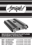
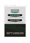
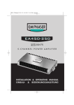
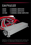
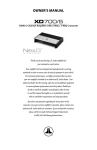
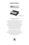
BEDIENUNGSANLEITUNG B OWNER’S MANUAL 6 635 &+$11(/$03/,),(T T 635&+$11(/$03/,),(5 6 5 635 &+$11(/$03/,),(5 6 5 Spectron_Manual_SP-R2200-R4100-1500.indd 1 9.10.2007 11:01:07 Uhr INHALTSVERZEICHNIS TECHNISCHE MERKMALE .......................................................................................................................................................... 4 ANSCHLÜSSE & BEDIENUNGSELEMENTE .... .......................................................................................................................... ...................................................................................................................... 5-14 SP-R 4100 .... ................................................................................................................................................................................. ............................................................................................................................................................................. 5-8 SP-R 2200 .... ................................................................................................................................................................................ ............................................................................................................................................................................ 9-11 SP-R 1500 .... ............................................................................................................................................................................... ........................................................................................................................................................................... 12-14 HINWEISE ZUR INSTALLATION ........... ................................................................................................................................................ ..................................................................................................................................... 15 MONTAGE DES VERSTÄRKERS ................................................................................................................................................ 17 VERKABELUNG / ELEKTRISCHER ANSCHLUSS ................................................................................................................... ............................................................................................................... 18-19 EINSTELLUNGEN .............. ................................................................................................................................................................ .................................................................................................................................................. 20-21 GARANTIE-BESTIMMUNGEN .............. ......................................................................................................................................... ........................................................................................................................... 44-46 2 Spectron_Manual_SP-R2200-R4100-1500.indd 2 9.10.2007 11:01:08 Uhr Besten Dank! Dass Sie sich zum Kauf dieses SPECTRON Car Hifi Verstärkers entschieden haben. Sie besitzen nun ein Produkt, dass durch den Einsatz hochwertiger Materialien und präziser Fertigungsmethoden hohe Leistung und lange Lebensdauer garantiert. Damit Sie die Wiedergabequalität und Leistungsfähigkeit dieses Verstärkers voll ausschöpfen können, bitten wir Sie, sich eingehend mit den Features und Einstellmöglichkeiten dieses Verstärkers vertraut zu machen. Lesen Sie deshalb diese Bedienungsanleitung sorgfältig durch und bewahren Sie diese Anleitung, die Kaufquittung und auch die Originalverpackung gut auf. 3 Spectron_Manual_SP-R2200-R4100-1500.indd 3 9.10.2007 11:01:09 Uhr TECHNISCHE MERKMALE MOS-FET Netzteil: Die Verstärker der SP-R Serie sind mit modernen leistungsstarken MOS-FET Netzteilen bestückt, die für eine hohe und stabile Ausgangsleistung sorgen. INTEGRIERTE ELEKTRONISCHE FREQUENZWEICHE: Die SPECTRON Verstärker verfügen über integrierte variable elektronische Frequenzweichen, mit einer Flankensteilheit von jeweils 12 dB/Okt. für Hoch- und Tiefpass. Je nach Verwendungszweck respektive den angeschlossenen Lautsprechersystemen, lassen sich am Verstärker Hochpassfilter, Tiefpassfilter bzw. Bandpass und Fullrange Betrieb wählen. SAUBERER INNENAUFBAU UND HOCHWERTIGE BAUTEILE: Durch die ausschließliche Verwendung von hochwertigen Materialien und der präzisen Fertigung ist die Betriebssicherheit der SPECTRON Verstärker auch im rauen Einsatz sichergestellt. INTELLIGENTE SCHUTZSCHALTUNG: Die integrierte Schutzschaltung erkennt Kurzschlüsse an den Lautsprecherausgängen, Gleichspannung im Ausgangssignal und überhöhte Betriebstemperatur. Fehlerhafte Betriebszustände führen zum sofortigen Abschalten des Gerätes. EXTERNE SICHERUNGEN: Für die Absicherung des internen Verstärker-Netzteiles befindet sich auf der Power-Eingansseite des Verstärkers eine entsprechende ATC Sicherung(en). Diese lassen sich schnell und einfach austauschen. 4 Spectron_Manual_SP-R2200-R4100-1500.indd 4 9.10.2007 11:01:09 Uhr 1 12 2 3 45 13 6 14 7 8 9 10 11 15 16 5 Spectron_Manual_SP-R2200-R4100-1500.indd 5 9.10.2007 11:01:10 Uhr ANSCHLÜSSE & BEDIENUNGSELEMENTE SP-R4100 FRONT PANEL 1 SCHIEBESCHALTER FÜR DEN BETRIEBSMODUS DER FRONT KANÄLE CH1/2 Schiebeschalter für die Festlegung der Arbeitsweise der integrierten elektronischen Frequenzweiche der FRONT Kanäle CH1/2 2 REGLER FÜR DIE HOCHPASS TRENNFREQUENZ DER FRONT KANÄLE CH1/2 Regler zum Einstellen der Hochpass-Trennfrequenz an der integrierten elektronischen Frequenzweiche der FRONT Kanäle CH1/2 3 REGLER FÜR DIE ANHEBUNG DES BASSBEREICHS DER FRONT KANÄLE CH1/2 Regler zum Anheben um bis zu 6dB 4 REGLER FÜR DIE EINGANGSEMPFINDLICHKEIT DER FRONT KANÄLE CH1/2 Eingangsempfindlichkeitsregler der Kanäle FRONT CH1/2, für die Anpassung an die Ausgangsspannung des Steuergerätes 5 CINCH-EINGÄNGE FRONT CH1/2 Eingangsbuchsen für den Anschluss der FRONT Cinch-Ausgänge des Steuergerätes an den Verstärker 6 CINCH-EINGÄNGE REAR CH3/4 Eingangsbuchsen für den Anschluss der REAR Cinch-Ausgänge des Steuergerätes an den Verstärker 6 Spectron_Manual_SP-R2200-R4100-1500.indd 6 9.10.2007 11:01:11 Uhr 7 REGLER EINGANGSEMPFINDLICHKEIT DER REAR KANÄLE CH3/4 Eingangsempfindlichkeitsregler der REAR Kanäle CH3/4, für die Anpassung an die Ausgangsspannung des Steuergerätes 8 REGLER FÜR DIE ANHEBUNG DES BASSBEREICHS DER REAR KANÄLE CH3/4 Regler zum Anheben um bis zu 6dB 9 REGLER FÜR DIE TIEF-/ BANDPASS TRENNFREQUENZ DER REAR KANÄLE CH3/4 Regler zum Einstellen der Tiefpass-Trennfrequenz an der integrierten elektronischen Frequenzweiche der Kanäle CH3/4 10 SCHIEBESCHALTER FÜR DEN BETRIEBSMODUS DER REAR KANÄLE CH3/4 Schiebeschalter für die Festlegung der Arbeitsweise der integrierten elektronischen Frequenzweiche der REAR Kanäle CH3/4 11 REGLER FÜR DIE HOCHPASS TRENNFREQUENZ DER REAR KANÄLE CH3/4 Regler zum Einstellen der Hochpass und Tiefpass Trennfrequenz an der integrierten elektronischen Frequenzweiche der REAR Kanäle CH3/4 7 Spectron_Manual_SP-R2200-R4100-1500.indd 7 9.10.2007 11:01:12 Uhr REAR PANEL 12 POWER/PROTECT LED Grüne „Power“ LED signalisiert den normalen Betriebszustand der Endstufe im eingeschalteten Zustand. Eine rot aufleuchtende LED signalisiert eine generelle Fehlfunktion der Endstufe, wie z.B. Kurzschluss an den Lautsprecherausgängen, Überhitzung sowie Gleichspannung an den LS-Ausgängen 13 „GND“ POWER EINGANGS-TERMINAL Anschlussterminal für das Massekabel von der Chassis-Masse des Fahrzeuges „REM“ EINGANGS-TERMINAL Anschlussterminal für das 12V Schaltsignal vom Headunit, welches die Endstufe ein- oder ausschaltet. „B+“ POWER EINGANGS-TERMINAL Anschlussterminal für das +12V Hauptstromkabel, angeschlossen über eine Sicherung an dem Pluspol der Fahrzeugbatterie 14 FUSE ATC-Sicherung für die interne Absicherung des Verstärkers gegen Überlastung und Fehlmanipulation 15 LAUTSPRECHER AUSGANGS-TERMINAL CH1/2 Lautsprecheranschlussterminal für den Anschluss von Lautsprechern, stereo oder gebrückt 16 LAUTSPRECHER AUSGANGS-TERMINAL CH3/4 Lautsprecheranschlussterminal für den Anschluss von Lautsprechern, stereo oder gebrückt 8 Spectron_Manual_SP-R2200-R4100-1500.indd 8 9.10.2007 11:01:12 Uhr 2 3 1 7 8 4 9 5 6 10 9 Spectron_Manual_SP-R2200-R4100-1500.indd 9 9.10.2007 11:01:13 Uhr ANSCHLÜSSE & BEDIENUNGSELEMENTE SP-R2200 FRONT PANEL 1 CINCH-EINGÄNGE CH1/2 Eingangsbuchsen für den Anschluss der Cinch-Ausgänge des Steuergerätes an den Verstärker 2 REGLER FÜR DIE EINGANGSEMPFINDLICHKEIT DER KANÄLE CH1/2 Eingangsempfindlichkeitsregler der Kanäle CH1/2, für die Anpassung an die Ausgangsspannung des Steuergerätes 3 REGLER FÜR DIE ANHEBUNG DES BASSBEREICHS DER KANÄLE CH1/2 Regler zum Anheben um bis zu 6dB 4 REGLER FÜR DIE TIEFPASS TRENNFREQUENZ DER KANÄLE CH1/2 Regler zum Einstellen der Tiefpass-Trennfrequenz an der integrierten elektronischen Frequenzweiche der Kanäle CH1/2 5 SCHIEBESCHALTER FÜR DEN BETRIEBSMODUS DER KANÄLE CH1/2 Schiebeschalter für die Festlegung der Arbeitsweise der integrierten elektronischen Frequenzweiche der Kanäle CH1/2 6 REGLER FÜR DIE HOCHPASS TRENNFREQUENZ DER KANÄLE CH1/2 Regler zum Einstellen der Hochpass-Trennfrequenz an der integrierten elektronischen Frequenzweiche der Kanäle CH1/2 10 Spectron_Manual_SP-R2200-R4100-1500.indd 10 9.10.2007 11:01:13 Uhr REAR PANEL 7 POWER/PROTECT LED Grüne „Power“ LED signalisiert den normalen Betriebszustand der Endstufe im eingeschalteten Zustand. Eine rot aufleuchtende LED signalisiert eine generelle Fehlfunktion der Endstufe, wie z.B. Kurzschluss an den Lautsprecherausgängen, Überhitzung sowie Gleichspannung an den LS-Ausgängen 8 „GND“ POWER EINGANGS-TERMINAL Anschlussterminal für das Massekabel von der Chassis-Masse des Fahrzeuges „REM“ EINGANGS-TERMINAL Anschlussterminal für das 12V Schaltsignal vom Headunit, welches die Endstufe ein- oder ausschaltet. „B+“ POWER EINGANGS-TERMINAL Anschlussterminal für das +12V Hauptstromkabel angeschlossen über eine Sicherung an den Pluspol der Fahrzeugbatterie 9 FUSE ATC-Sicherung für die interne Absicherung des Verstärkers gegen Überlastung und Fehlmanipulation 10 LAUTSPRECHER AUSGANGS-TERMINAL CH1/2 Lautsprecheranschlussterminal für den Anschluss von Lautsprechern, stereo oder gebrückt 11 Spectron_Manual_SP-R2200-R4100-1500.indd 11 9.10.2007 11:01:14 Uhr 1 7 2 3 8 4 9 5 6 10 12 Spectron_Manual_SP-R2200-R4100-1500.indd 12 9.10.2007 11:01:15 Uhr ANSCHLÜSSE & BEDIENUNGSELEMENTE SP-R1500 FRONT PANEL 1 CINCH-EINGÄNGE CH1/2 Eingangsbuchsen für den Anschluss der Cinch-Ausgänge des Steuergerätes an den Verstärker 2 REGLER FÜR DIE EINGANGSEMPFINDLICHKEIT DER KANÄLE CH1/2 Eingangsempfindlichkeitsregler der Kanäle CH1/2, für die Anpassung an die Ausgangsspannung des Steuergerätes 3 REGLER FÜR DIE SUBSONIC TRENNFREQUENZ DER KANÄLE CH1/2 Regler zum Einstellen der Subsonic-Trennfrequenz an der integrierten elektronischen Frequenzweiche der Kanäle CH1/2 4 REGLER FÜR DIE TIEFPASS TRENNFREQUENZ DER KANÄLE CH1/2 Regler zum Einstellen der Tiefpass-Trennfrequenz an der integrierten elektronischen Frequenzweiche der Kanäle CH1/2 5 REGLER FÜR DIE ANHEBUNG DES BASSBEREICHS Regler zum Anheben um bis zu 6dB 6 EINGANG FÜR DIE BASSPEGEL-FERNBEDIENUNG Die Basspegel-Fernbedienung dient der komfortableren Bedienung des Basspegels vom Fahrerplatz aus 13 Spectron_Manual_SP-R2200-R4100-1500.indd 13 9.10.2007 11:01:15 Uhr REAR PANEL 7 POWER/PROTECT LED Grüne „Power“ LED signalisiert den normalen Betriebszustand der Endstufe im eingeschalteten Zustand. Eine rot aufleuchtende LED signalisiert eine generelle Fehlfunktion der Endstufe, wie z.B. Kurzschluss an den Lautsprecherausgängen, Überhitzung sowie Gleichspannung an den LS-Ausgängen 8 „GND“ POWER EINGANGS-TERMINAL Anschlussterminal für das Massekabel von der Chassis-Masse des Fahrzeuges „REM“ EINGANGS-TERMINAL Anschlussterminal für das 12V Schaltsignal vom Headunit, welches die Endstufe ein- oder ausschaltet. „B+“ POWER EINGANGS-TERMINAL Anschlussterminal für das +12V Hauptstromkabel angeschlossen über eine Sicherung an den Pluspol der Fahrzeugbatterie 9 FUSE ATC-Sicherungen für die interne Absicherung des Verstärkers gegen Überlastung und Fehlmanipulation 10 LAUTSPRECHER AUSGANGS-TERMINAL Lautsprecheranschlussterminal für den Anschluss von Lautsprechern 14 Spectron_Manual_SP-R2200-R4100-1500.indd 14 9.10.2007 11:01:16 Uhr HINWEISE ZUR INSTALLATION Für die Montage und den Anschluss dieses Verstärkers benötigen Sie entsprechendes Montagezubehör, wie z.B. Stromkabel, Cinchkabel, Batterie- und Masseklemmen etc., welches nicht im Lieferumfang der Endstufe enthalten ist. Dieses Zubehör können Sie bei Ihrem SPECTRON Fachhändler erwerben. Der Verstärker sollte stabil und sicher montiert werden. Achten Sie auf ausreichende Luftzufuhr am Montageort. Die Endstufe darf – weil der Kühlkörper Wärme abführen muss – nicht völlig „zugebaut“ werden. Die Kabelführung (Cinchkabel!) sowie der Massepunkt für den Anschluss des -12V Stromversorgungs-Kabels für die Endstufe am Fahrzeug hat einen entscheidenden Einfluss auf das störungsfreie Funktionieren der Anlage! 15 Spectron_Manual_SP-R2200-R4100-1500.indd 15 9.10.2007 11:01:16 Uhr VERKABELUNG STROMKABEL Der Stromkabel-Querschnitt sollte - bei einer Gesamtlänge von 5m – 10mm2 nicht unterschreiten. Dies gilt für beide Hauptstromkabel, also +12V und Massekabel. Falls die Endstufe im Brückenmodus betrieben wird, oder zwei Endstufen im Anlagenkonzept enthalten sind, ist für ein Haupt-Stromkabelquerschnitt von mindestens 16mm2 zu sorgen. Diese Stromkabelstärken garantieren eine problemlose Funktion dieses Verstärkers, eine volle Leistungsabgabe und sie verhindern auch eine Überhitzung! CINCHKABEL Verwenden Sie zum Anschluss dieser SPECTRON Endstufe an Ihr Steuergerät mindestens doppelt geschirmte oder sogenannte Twisted Pair Cinchkabel. Die signalführenden Cinchkabel müssen immer mit so großem Abstand wie möglich von allen potentiellen „elektrischen Störsendern“ wie Bordcomputer, Benzinpumpe, Steuerungen, etc. verlegt werden. MINIMALE LASTIMPEDANZ Die Kühlkapazität dieser Endstufe und die Verstärkerschaltung sind für Lasten von 2 Ohm stereo, oder 4 Ohm mono gebrückt ausgelegt. Vermeiden Sie den Anschluss von tieferen Lastimpedanzen, die Endstufe würde überhitzen und könnte sogar Schaden nehmen. THERMAL SHUTDOWN TIME Bei maximaler Auslastung, d.h. alle Kanäle gebrückt und maximal möglicher Lautstärke, reagiert die Schutzschaltung des Verstärker bei normaler Temperaturumgebung innerhalb folgender Zeiten: SP-R2200 < 10 min. SP-R4100 < 10 min. SP-R1500 < 10 min. Die Zeit kann je nach Umgebungstemperatur variieren. Das Abschalten dient dem Zweck, das die Bauteile vor zu starker Hitzeentwicklung geschützt werden und Sie so bedeutend länger Freude an Ihrem SPECTRON Verstärker haben. 16 Spectron_Manual_SP-R2200-R4100-1500.indd 16 9.10.2007 11:01:17 Uhr MONTAGE DES VERSTÄRKERS MONTAGEORT Suchen Sie einen geeigneten Montageort und stellen Sie eine ausreichende Belüftung sicher (mindestens 5 cm Freiraum seitlich und oberhalb der Endstufe). Dies ist wichtig, weil sich der Verstärker bei Überhitzung sonst abschaltet. Montageorte mit „unbekanntem Hintergrund“ sollten gemieden werden. Es könnten sich Objekte dahinter befinden, die man besser nicht anbohrt, wie z.B. ein Benzintank, hydraulische Bremsleitungen, Kabelbäume usw.! Der Ort sollte außerdem trocken und nach der Montage noch zugänglich sein – für die Einstellarbeiten am Bedienfeld. ACHTUNG! Entfernen Sie zu Ihrer eigenen Sicherheit erst das Minuskabel vom Minuspol der Batterie! Achten Sie darauf, das es zu keinem unbeabsichtigten Kontakt kommen kann! Halten Sie den Verstärker an den gewünschten Ort und markieren Sie mit einem geeigneten Filzstift die Bohrposition der Befestigungslöcher. Bohren Sie die angezeichneten Löcher mit einem 2,5 oder 3 mm Bohrer. Drücken Sie die beigelegten Gummitüllen in die Befestigungslöcher Ihres Verstärkers, der Verstärker muss immer von der Fahrzeugmasse isoliert befestigt werden, es können sonst Masseschleifen auftreten, die sich mit einem lauten Pfeifen äußern! Legen Sie nun den Verstärker auf die vorgebohrten Löcher und schrauben Sie ihn an. 17 Spectron_Manual_SP-R2200-R4100-1500.indd 17 9.10.2007 11:01:18 Uhr VERKABELUNG / ELEKTRISCHER ANSCHLUSS VERLEGEN VON CINCH UND REMOTE KABELN Verlegen Sie das oder die Cinchkabel und das Remote-Kabel vom Steuergerät zur Endstufe. Diese Kabel müssen räumlich getrennt von der Stromzuführung des Verstärkers eingezogen werden. Schließen Sie das Remote-Kabel an das mit „REM“ bezeichnete Terminal an der Endstufe und an das mit Antenna-Rem. oder Amplifier-Rem. bezeichnete Kabel Ihres Steuergerätes an. Anschließend stecken Sie die Cinchkabel in die Cinch-Eingangsbuchsen des Verstärkers ein. Beachten Sie hierbei die Seitenkennung, d.h. 1-CH ist links, 2-CH ist rechts, usw. ANSCHLUSS DER LAUTSPRECHERKABEL Schließen Sie nun die Lautsprecherkabel an den Terminals des Verstärkers an. Beachten Sie hierbei UNBEDINGT die richtige Polung der Lautsprecherkabel am Terminal (Plus auf Plus, Minus auf Minus). Ziehen Sie die Schrauben der LS-Terminals satt an. 18 Spectron_Manual_SP-R2200-R4100-1500.indd 18 9.10.2007 11:01:18 Uhr VERLEGEN UND ANSCHLIESSEN DER HAUPT-STROMKABEL Verlegen Sie das Pluskabel direkt von der Batterie zum Verstärker. Innerhalb der ersten 30 cm nach dem Pluspolklemmenabgriff muss immer eine Hauptsicherung angebracht werden. Dies dient zur Absicherung des Pluskabels gegen Kurzschluss auf Fahrzeug-Masse und den möglicherweise resultierenden Kabelbrand, und nicht der Absicherung der Endstufenelektronik! Verwenden Sie eine dem Stromkabelquerschnitt entsprechende Sicherung. Die Sicherung darf erst nach Abschluss aller weiter folgenden Montagearbeiten in den Sicherungshalter gesteckt werden! Schließen Sie das Minuskabel am Verstärker und am Fahrzeug an. Versuchen Sie immer, das Massekabel so kurz wie möglich zu halten. Es sollte denselben Querschnitt wie das Pluskabel besitzen und achten Sie auf eine perfekt gesäuberte blanke Metalloberfläche dort, wo das Ringterminal der Masseleitung angeschraubt wird. Schlechte Massepunkte sind der Hauptgrund für später auftretende Störungen, wie z.B. Lichtmaschinenpfeifen! Schließen Sie den Stromkreis zum Verstärker durch Einsetzen der Hauptsicherung. Ihr Verstärker sollte nun beim Einschalten des Steuergerätes durch aufleuchten der grünen Power-LED die Betriebsbereitschaft anzeigen. Leuchtet die rote Protection-LED auf, ist Ihre Installation fehlerhaft. Gehen Sie alle vorangehenden Installationsanweisungen nochmals genau durch. 19 Spectron_Manual_SP-R2200-R4100-1500.indd 19 9.10.2007 11:01:19 Uhr EINSTELLUNGEN FREQUENZWEICHE BETRIEBSWAHLSCHALTER Die Arbeitsweise der integrierten elektronischen Frequenzweiche kann über den Schiebeschalter definiert werden. Dies sollte entsprechend dem angeschlossenen Lautsprechersystem auf entweder LPF oder HPF gestellt werden. Die SP-R4100 verfügt über zwei dieser Schalter, für jedes Kanalpaar separat. Der durch diese Einstellung resultierende Hoch- (HPF) oder Tiefpass (LPF) bzw. Bandpass (BPF) teilt dem oder den eingesetzten Lautsprechersystem(en) wie z.B. Subwoofer, Koax- oder Kompo nur den Frequenzbereich zu, der dieses System sauber und ohne Verzerrungen verarbeiten kann. HOCHPASS-TRENNFREQUENZ Die Einstellung der Trennfrequenz des Hochpasses (HPF) sorgt für eine elektrische und mechanische Entlastung der verwendeten Koaxial- oder Komponentensysteme im Bassbereich. Je nach Größe und Belastbarkeit des Lautsprechers sollte die Hochpass-Trennfrequenz im Bereich zwischen 50 bis 150Hz liegen. Diese Einstellung wird über das entsprechende Potentiometer vorgenommen. Wenn Sie die Hochpassfrequenz zu tief einstellen, kommt der angeschlossene 10 bis 16cm Satellitenlautsprecher recht schnell mechanisch an seine Grenze im Bassbereich. Die Folge sind hörbare Verzerrungen schon bei mittleren Lautstärken. Entsprechend ist bei zu hoch eingestellter Hochpass-Trennfrequenz der Klang im oberen Bassbereich dünn und kraftlos. TIEFPASS- UND BANDPASSTRENNFREQUENZ Beim Betrieb eines Subwoofers (gebrückt oder zwei Einzelschassis stereo) müssen Sie den Schiebeschalter auf LPF stellen, damit der Subwoofer nur Bass-Signale vom Verstärker erhält. Stellen Sie die Tiefpass Trennfrequenz am Potentiometer auf ca. zwischen 50 bis 90 Hz. Die effektive Trennfrequenz ist schlussendlich Geschmackssache und hängt sowohl vom Fahrzeug und vom Frequenzgang des angeschlossenen Subwoofers ab. Anhaltspunkt: Eine zu tiefe Trennfrequenz lässt den Bassbereich kraftlos und unkonturiert wirken. Eine zu hohe Trennfrequenz bewirkt ein Dröhnen des Bassbereichs. Um die ultratiefen Bassfrequenzen herauszufiltern, drehen Sie den HPF-Regler auf 20-30Hz. Damit entlasten Sie den angeschlossenen Lautsprecher um die Frequenzen, die er nur schwer oder gar nicht wiedergeben kann. 20 Spectron_Manual_SP-R2200-R4100-1500.indd 20 9.10.2007 11:01:19 Uhr ANPASSUNG DER EINGANGSEMPFINDLICHKEIT Bevor Sie mit der Anpassung der Eingangsempfindlichkeit(en) anfangen, müssen erst alle Klangregler, wie z.B. Bass, Treble, Fader/Balance und Loudness in ihre jeweilige Mittel- bzw. Neutral Position gebracht werden. Wenn ein Subwoofersystem in der Gesamtanlage enthalten ist, muss immer dessen Eingangsempfindlichkeit als erstes angepasst werden. Die Anpassung aller weiteren (Satelliten)Lautsprecher erfolgt nach der Einstellung des Subwoofer Referenzpegels! Drehen Sie nun das mit GAIN bezeichnete Potentiometer vom Kanalpaar des Subwoofers im Gegenuhrzeigersinn auf die Minimum-Position. Schalten Sie das Steuergerät ein und stellen Sie den Lautstärkeregler auf ca. 3/4 der Maximallautstärke. Benutzen Sie für die nun folgende Eingangsempfindlichkeits-Einstellung ein gut aufgenommenes und dynamikreiches Musikstück. Drehen Sie den GAIN Regler am Verstärker langsam im Uhrzeigersinn auf, bis Sie gerade die Verzerrungsgrenze im Bassbereich erreichen. Stellen Sie jetzt die Lautstärke an Ihrem Steuergerät auf einen mittleren Wert zurück, und drehen Sie den GAIN Regler vom Kanalpaar der Frontsysteme (z.B. Satelliten in den Vordertüren) langsam auf. „Dosieren“ Sie die Lautstärke des vorderen Lautsprechersystems so zum Bass hinzu, dass sich ein ausgewogener und basskräftiger Klang einstellt. Wenn mit dem SPECTRON Verstärker kein Subwoofer angesteuert wird, muss das Lautsprechersystem, welches am lautesten spielen soll, zuerst eingestellt werden – danach folgen wenn vorhanden, weitere Kanalpaare. 21 Spectron_Manual_SP-R2200-R4100-1500.indd 21 9.10.2007 11:01:20 Uhr CONTENT KEY DESIGN FEATURES ......................................................................................................................................................... 24 CONNECTIONS & CONTROLS .................... ........................................................................................................................................... ....................................................................................................................... 25-34 SP-R 4100 .................... ............................................................................................................................................................................. ......................................................................................................................................................... 25-28 SP-R 2200 .................... .............................................................................................................................................................................. .......................................................................................................................................................... 29-31 SP-R 1500 .................... .............................................................................................................................................................................. .......................................................................................................................................................... 32-34 INSTALLATION ........................... .......................................................................................................................................................................... ............................................................................................................................................... 35 AMPLIFIER MOUNTING .......................................................................................................................................................... 37 CABLE ROUTING .... ...................................................................................................................................................................... .................................................................................................................................................................. 38 ADJUSTMENTS .................................................................................................................................................................. ................................................................................................................................................................ 39-40 LIMITED WARRANTY .............. ........................................................................................................................................................ .......................................................................................................................................... 43-46 22 Spectron_Manual_SP-R2200-R4100-1500.indd 22 9.10.2007 11:01:21 Uhr Congratulations! And thank you for choosing this SPECTRON car audio power amplifier! You now own a high quality amplifier that was manufactured with advanced assembly methods, giving you a long service life and high power output. To maximize the performance of this amplifier, we recommend that you acquaint yourself thoroughly with all technical features and all implemented control functions. Read this manual carefully, before you attempt the installation of this amp. Please retain this manual, the original packing and your purchasing / installation receipts for future reference. 23 Spectron_Manual_SP-R2200-R4100-1500.indd 23 9.10.2007 11:01:21 Uhr KEY DESIGN FEATURES MOSFET POWER SUPPLY: This SPECTRON amplifier features a PWM modulated MOS-FET power supply, to give you high power output and stability into 2 ohm loads in stereo mode. INTEGRATED ELECTRONIC CROSSOVER: This SPECTRON amplifier features an integrated electronic crossover with independently selectable Highpass and Lowpass/Bandpass filtering, as well as Fullrange loop through. The filters slopes of the High- and Lowpass section both feature 12 dB/octave. CLEAN LAYOUT & HIGH QUALITY PARTS: Only high quality parts and electronic components have been used for the assembly of this SPECTRON amplifier. Precision assembly and final QC inspections guarantee flawless performance. ADVANCED PROTECTION CIRCUITRY: The protection circuitry safeguards the amplifier from short-circuits at the speaker outputs, DC offset voltage at the outputs and overheating of power electronics. EXTERNAL FUSE: The input side panel of this amplifier is equipped with an ATC type fuse holders, for a fast and convenient exchange of blown fuses. 24 Spectron_Manual_SP-R2200-R4100-1500.indd 24 9.10.2007 11:01:22 Uhr 1 12 2 3 45 13 6 14 78 9 10 11 15 16 25 Spectron_Manual_SP-R2200-R4100-1500.indd 25 9.10.2007 11:01:22 Uhr CONNECTIONS & CONTROLS SP-R4100 FRONT PANEL 1 OPERATION MODE SWITCH FRONT CH1/2 Slide switch to select the operation mode of the electronic crossover driving the CH1/2 channel section of the amplifier 2 HIGHPASS FREQUENCY CONTROL FRONT CH1/2 Control potentiometer for the Highpass crossover frequency adjustment of the FRONT CH1/2 channel section 3 BASSBOOST CONTROL FRONT CH1/2 Increases the bass frequencies up to 6dB 4 INPUT GAIN CONTROL FRONT CH1/2 Input gain control potentiometer for the FRONT CH1/2 amplifier section, to match the output voltage of the head unit’s RCA line-outs to the amplifier input 5 FRONT RCA INPUTS CH1/2 Low-level stereo RCA inputs for connection with the front line-outs of the head-unit 6 REAR RCA INPUTS CH3/4 Low-level stereo RCA inputs for connection with rear the line-outs of the head-unit 26 Spectron_Manual_SP-R2200-R4100-1500.indd 26 9.10.2007 11:01:23 Uhr 7 INPUT GAIN CONTROL REAR CH3/4 Input gain control potentiometer for REAR CH3/4 amplifier section, to match the output voltage of the headunit’s RCA line-outs to the amplifier input 8 BASSBOOST CONTROL REAR CH3/4 Increases the bass frequencies up to 6dB 9 LOWPASS FREQUENCY CONTROL FRONT CH3/4 Control potentiometer for the Lowpass/Bandpass crossover frequency adjustment of the REAR CH3/4 channel section 10 OPERATION MODE SWITCH REAR CH3/4 Slide switch to select the operation mode of the electronic crossover driving the CH3/4 channel section of the amplifier 11 HIGHPASS FREQUENCY CONTROL REAR CH3/4 Control potentiometer for the Highpass crossover frequency adjustment of the 3/4-CH channel section of the amplifier 27 Spectron_Manual_SP-R2200-R4100-1500.indd 27 9.10.2007 11:01:24 Uhr REAR PANEL 12 POWER/PROTECT LED Green “operation” LED is lit when the amp is turned ON, signaling correct operation. Red illuminated LED is signaling faulty speaker connections or general malfunction of the amplifier 13 POWER INPUT TERMINAL “GND“ Terminal to connect the amplifier to the negative or ground pole of the vehicle REMOTE INPUT TERMINAL “REM” Terminal to connect the amplifier to the automatic (remote) turn-on / turn-off lead of the head unit POWER INPUT TERMINAL “B+“ Terminal to connect the amplifier to the positive +12V voltage of the car battery 14 FUSE ATC fuse(s) for protection of the amplifier electronics against overload or wrong operation 15 SPEAKER OUTPUT TERMINALS Output terminal to connect the front speakers in stereo or bridged mode to the amplifier 16 SPEAKER OUTPUT TERMINALS Output terminal to connect the rear speakers in stereo or bridged mode to the amplifier 28 Spectron_Manual_SP-R2200-R4100-1500.indd 28 9.10.2007 11:01:24 Uhr 1 7 2 3 8 4 9 5 6 10 29 Spectron_Manual_SP-R2200-R4100-1500.indd 29 9.10.2007 11:01:25 Uhr CONNECTIONS & CONTROLS SP-R2200 FRONT PANEL 1 RCA INPUTS CH1/2 Low-level stereo RCA inputs for connection with the line-outs of the head-unit 2 INPUT GAIN CONTROL CH1/2 Input gain control potentiometer for CH1/2 amplifier section, to match the output voltage of the head unit’s RCA line-outs to the amplifier input 3 BASSBOOST CONTROL CH1/2 Increases the bass frequencies up to 6dB 4 LOWPASS FREQUENCY CONTROL CH1/2 Control potentiometer for the Lowpass crossover frequency adjustment of the CH1/2 channel section 5 OPERATION MODE SWITCH CH1/2 Slide switch to select the operation mode of the electronic crossover driving the CH1/2 channel section of the amplifier 6 HIGHPASS FREQUENCY CONTROL CH1/2 Control potentiometer for the Highpass crossover frequency adjustment of the CH1/2 channel section 30 Spectron_Manual_SP-R2200-R4100-1500.indd 30 9.10.2007 11:01:25 Uhr REAR PANEL 7 POWER/PROTECT LED Green “operation” LED is lit when the amp is turned ON, signaling correct operation. Red illuminated LED is signaling faulty speaker connections or general malfunction of the amplifier 8 POWER INPUT TERMINAL “GND“ Terminal to connect the amplifier to the negative or ground pole of the vehicle REMOTE INPUT TERMINAL “REM” Terminal to connect the amplifier to the automatic (remote) turn-on / turn-off lead of the head unit POWER INPUT TERMINAL “B+“ Terminal to connect the amplifier to the positive +12V voltage of the car battery 9 FUSE ATC fuse(s) for protection of the amplifier electronics against overload or wrong operation 10 SPEAKER OUTPUT TERMINALS Output terminal to connect the front speakers in stereo or bridged mode to the amplifier 31 Spectron_Manual_SP-R2200-R4100-1500.indd 31 9.10.2007 11:01:26 Uhr 1 7 2 3 8 4 9 5 6 10 32 Spectron_Manual_SP-R2200-R4100-1500.indd 32 9.10.2007 11:01:27 Uhr CONNECTIONS & CONTROLS SP-R1500 FRONT PANEL 1 RCA INPUTS CH1/2 Low-level stereo RCA inputs for connection with the line-outs of the head-unit 2 INPUT GAIN CONTROL CH1/2 Input gain control potentiometer for CH1/2 amplifier section, to match the output voltage of the head unit’s RCA line-outs to the amplifier input 3 SUBSONIC FILTER FREQUENCY CONTROL CH1/2 Control potentiometer for the subsonic filter frequency adjustment of the CH1/2 channel section 4 LOWPASS FREQUENCY CONTROL CH1/2 Control potentiometer for the Lowpass crossover frequency adjustment of the CH1/2 channel section 5 BASSBOOST CONTROL CH1/2 Increases the bass frequencies up to 6dB 6 PORT FOR REMOTE CONTROL 33 Spectron_Manual_SP-R2200-R4100-1500.indd 33 9.10.2007 11:01:27 Uhr REAR PANEL 7 POWER/PROTECT LED Green “operation” LED is lit when the amp is turned ON, signaling correct operation. Red illuminated LED is signaling faulty speaker connections or general malfunction of the amplifier 8 POWER INPUT TERMINAL “GND“ Terminal to connect the amplifier to the negative or ground pole of the vehicle REMOTE INPUT TERMINAL “REM” Terminal to connect the amplifier to the automatic (remote) turn-on / turn-off lead of the head unit POWER INPUT TERMINAL “B+“ Terminal to connect the amplifier to the positive +12V voltage of the car battery 9 FUSE ATC fuse(s) for protection of the amplifier electronics against overload or wrong operation 10 SPEAKER OUTPUT TERMINALS Output terminal to connect the front speakers in stereo or bridged mode to the amplifier 34 Spectron_Manual_SP-R2200-R4100-1500.indd 34 9.10.2007 11:01:28 Uhr INSTALLATION To install this SPECTRON amplifier, you have to buy additional accessories like power cables, RCA interconnects, main fuse holder, i.e. to properly connect your amplifier to the on-board voltage system in your vehicle and the installed head unit. To obtain best performance and power output, it is recommended to use good quality accessory material only. Furthermore, consider a safe mounting of the amplifier, sufficient ventilation and convenient accessibility of all the side panel controls a.s.o. Please note that - because of possible interference problems with the existing car electrics and electronics the routing of the RCA signal cables and the chassis ground connection are crucial steps during the install of this amp, and care must be applied to obtain a noise free and reliable performance. 35 Spectron_Manual_SP-R2200-R4100-1500.indd 35 9.10.2007 11:01:28 Uhr GENERAL INFO ABOUT WIRES MAIN POWER CABLE CROSS SECTION The minimum power cable cross-section for this SPECTRON amplifier is 10mm2. If you intend to bridge this amplifier driving a subwoofer, or if two amplifiers are to be mounted in your vehicle, the minimum power cable cross section is 16mm2. These recommendations guarantee trouble free operation of your amplifiers, giving you full power output. Using main power cables with smaller cross sections may result in over-heating of the internal amplifier circuitry and elevated distortions. RCA INTERCONNECTS Use at least double shielded RCA interconnect cables. Keep in mind, that the RCA interconnects should always be kept far away from any potential sources of electrical interferences, for example try to avoid crossing electronic vehicle management systems (like engine computers, relays, wire harness a.s.o.). MINIMUM SPEAKER IMPEDANCES The internal amplifying circuitry and the heat dissipation capacity of this amplifier’s heatsink has been designed to cope with 2 ohm impedance loads in stereo mode or 4 ohms in bridge mode. Therefore, you can drive 4 to 2 ohm satellite speaker systems – or 4 ohm subwoofer systems in bridged operation mode. Do NOT operate this amplifier bridged into 2 ohm loads; the amp electronics may get damaged!!!! THERMAL SHUTDOWN TIME At maximum power output, i.e. all channels bridged and playing at maximum level, the protection circuitry shuts down the amplifier to protect against excess heat within the following time span: SP-R1500 < 10 min. SP-R2200 < 10 min. SP-R4100 < 10 min. The thermal shutdown time depends on the ambient temperature. The shutdown safeguards the electronics against overheating and prolongates the life of the amplifier. 36 Spectron_Manual_SP-R2200-R4100-1500.indd 36 9.10.2007 11:01:29 Uhr AMPLIFIER MOUNTING MOUNTING LOCATION Check the suitability of your preferred amplifier location carefully, before you start installation attempts. Always try to choose a place where you can be sure nothing gets damaged behind or below the panel, by drilling the holes for the amplifier mounting screws. Be aware that after the amp has been mounted, there should be a clearance of at least 5cm on all sides, for best cooling and to access the side panel for the adjustments of the electronic crossover. Attention! For your own safety, disconnect the negative battery terminal (GND) or remove the main fuse of the 12V power cable, before you start any wiring work! Once the location where the amplifier will be mounted is found, use the unit as a template and mark the mounting holes with pencil or felt-tip marker. Pilot-drill these holes, using a 2,5mm or 3mm drill bit on your power drill. Insert the supplied rubber washers into the mounting holes of the amp. The amplifier must be mounted totally isolated from the vehicle’s chassis ground, or metal parts. Now bolt the unit in place with the supplied self tapping screws. 37 Spectron_Manual_SP-R2200-R4100-1500.indd 37 9.10.2007 11:01:29 Uhr CABLE ROUTING RCA INTERCONNECTS AND REMOTE WIRING Run the RCA interconnects and the remote lead from the head-unit to the amplifier. Note that RCA interconnects must be routed separately from the main +12V power cable. Connect the remote (turn on/turn off) lead to the REM input terminal of the amplifier and to the remote output lead of your head-unit. Now plug in the RCA interconnects to the line-outs of the head-unit and to the RCA inputs of the amplifier. Pay attention when connecting the RCA cables: The left line out must be connected to L-CH input, the right line out must be connected to R-CH input. LOUDSPEAKER WIRE ROUTING Once the speaker cables have been routed, turn loose the speaker terminal screws and after inserting the stripped speaker cables, tighten up the screws. Always maintain correct electrical polarity of speaker wires to the respective terminal („+“ to „+“; „-„ to „-„). MAIN POWER CABLES Run the positive main power cable („+12 V“) directly from the positive terminal of the car battery to the amplifier. For protection of your car audio system against electrical short cuts and fire hazards, you must insert a fuse holder within the first 30cm of the positive main power cable. The applicable fuse value must match to the limitations of your main power cable cross section and serves to protect the vehicle from a shortcut of the +12V cable to chassis ground! Connect the ground cable to the ground terminal input of your amplifier and the other side of the cable to a rust free ground point in your vehicle. Keep the ground cable („-12V“) as short as possible. The ground power cable must have the same cross-section as the positive power cable. Tighten up both power input terminals, and double check for perfect and solid fit! 38 Spectron_Manual_SP-R2200-R4100-1500.indd 38 9.10.2007 11:01:30 Uhr ADJUSTMENT OF THE INTERNAL CROSSOVER OPERATION MODE Before you power up your amplifier, you must select and set the appropriate operation mode first. The operation mode is set, depending on the speaker system connected to the corresponding channel pair of the amplifier. For example select the Highpass (HPF) setting of the CROSSOVER slide-switch, if the speaker system driven by the corresponding channel pair is a component-, coaxial- or triaxial- type. Or else, set the operation mode switch to Lowpass/Bandpass (LPF/BPF), if the channel pair is intended to drive a subwoofer system. Highpass or Lowpass filtering allows the connected loudspeakers to work in the frequency bands they can reproduce best, reducing mechanical stress. HIGHPASS CROSSOVER FREQUENCY ADJUSTMENT For satellite speakers, set the operation mode slide switch to the “HPF position and then adjust the Highpass crossover frequency point, using the potentiometer, to set a desired x-over frequency. Depending on the effective cone surface and the power handling of the installed ‘satellite’ speaker system, it is recommended to set the x-over frequency in between 50 to 150Hz. This setting must be determined by ear, since it represents a compromise where either midbass reproduction or power handling has to be sacrificed! Note: If the Highpass crossover frequency is set too low, the speakers will be mechanically overdriven by low volume levels. If this frequency is adjusted at a point too high, too much mid/bass is cut off and the music played back will sound thin. 39 Spectron_Manual_SP-R2200-R4100-1500.indd 39 9.10.2007 11:01:31 Uhr LOWPASS CROSSOVER FREQUENCY ADJUSTMENT Set the operation mode switch to its “LPF” position, to drive a subwoofer system. The Lowpass crossover frequency should be played by ear as well, i.e. since this crossover frequency point is mostly a matter of personal taste and also depends on the vehicle itself and the subwoofer connected to the amp. As a rule of thumb, settings in a range between 60 to 90 Hz will render best sonic results. In general, setting the Lowpass crossover frequency point too low, will result in a weak and muddy sounding bass, while setting this crossover frequency too high will result in a ‘booming’ bass sound and reduced low end extension. INPUT GAIN CONTROL ADJUSTMENT Before you adjust the input gain level of the amp, to get the best signal to noise ratio from your amp / headunit combination, you must set all tone controls (Bass, Mid, Treble, Loudness etc.) and the fader on the headunit to the neutral or center positions. Now turn all input gain controls of the installed amplifiers anti-clockwise to their minimum positions and ALWAYS start with the channel pair, that drives the subwoofer system (if applicable). SUBWOOFER CHANNEL Set the volume control of your head-unit to approximately ¾ of full volume, while playing a dynamic track with good bass content. Slowly increase the input gain control of the channel pair on the amp, driving the subwoofer(s), by turning the input LEVEL potentiometer clockwise until you can just hear distorted sounds. Reduce the main volume level of your head-unit to a medium listening level and continue to set the remaining input gain levels. SATELLITE CHANNELS Slowly increase the input gain control of the remaining channel pair, for example the section that drives the front door installed speaker system, by turning the LEVEL control clockwise until you reach a good tonal balance with a slight emphasis of the bass range. Finally turn up the input level gain of all remaining channel pairs if applicable, to reach a good balance of the front, rear and subwoofer playback levels in your car. You’re done! 40 Spectron_Manual_SP-R2200-R4100-1500.indd 40 9.10.2007 11:01:31 Uhr TECHNICAL SPECIFICATIONS Model SP-R2200 SP-R4100 SP-R1500 Peak Power Output At 4 Ohms load / 14.4V (THD<=1.0%) All channels driven simultaneously 85W x 2 53W x 4 200W x 1 Rated Power Output (RMS) At 4 Ohms load / 14.4V (THD<=0.3%) All channels driven simultaneously 80W x 2 50W x 4 195W x 1 Power Output At 2 Ohms load / 14.4V (THD<=1.0%) All channels driven simultaneously 150W x 2 68W x 4 310W x 1 Bridged Power Output At 4 Ohms load / 14.4V (THD<=1.0%) All channels driven simultaneously 230W x 1 130W x 2 N/A Damping Factor All Channels stereo @ 4Ohms/100Hz > 130 > 100 > 100 Signal-to-Noise Ratio (A-weighted - all channels) > 90 dB > 90 dB > 91 dB Frequency Response (all channels, frequency filtering controls deactivated, 0 dB / - 1 dB) 10 Hz - 29 kHz 10 Hz – 25 kHz 10 Hz – 250 Hz 41 Spectron_Manual_SP-R2200-R4100-1500.indd 41 9.10.2007 11:01:32 Uhr Channel Separation (all channels) > 50 dB > 50 dB N/A Input Sensitivity (all channels) 200 mV – 6 V 200 mV – 6 V 200 mV – 6 V Integrated Active Filtering X-Over Slope Rates Variable Cross-Over Frequency 12 dB / oct. 40 – 300 Hz 12 dB / oct. 20/40 – 300 Hz 12 dB / oct. 50 – 250 Hz Subsonic Filter - - 15 - 50 Hz Fuses 1 x 30A ATC 1 x 40A ATC 2 x 20A ATC Dimensions (W x D x H) mm 264 x 270 x 60 314 x 270 x 60 334 x 270 x 60 42 Spectron_Manual_SP-R2200-R4100-1500.indd 42 9.10.2007 11:01:32 Uhr LIMITED WARRANTY Dear customer, please keep the original packing, the sales receipt and carefully read the warranty specifications given below! Should this SPECTRON amplifier require warranty service, please return it to the retailer from whom it was purchased, or the distributor in your country. This amplifier is fully warranted against defective materials or workmanship for a period of two years from date of purchase at retail. Warranty work will not be carried out unless this warranty certificate is presented fully completed with serial number, purchaser‘s address, purchasing date and dealer stamp together with the original sales slip. WARRANTY LIMITATIONS This warranty does not cover any damage due to: 1. Unauthorized or unapproved installation, incorrect audio or mains connection(s). 2. Exposure to excessive humidity, fluids, sun rays or excessive dirt or dust. 3. Accidents or abuse, unauthorized repair attempts and modifications not explicitly authorized by the manufacturer. This warranty is limited to the repair or the replacement of the defective product at the manufacturer‘s option and does not include any other form of damage, whether incidental, consequential or otherwise. The warranty does not cover any transport costs or damages caused by transport or shipment of the product. 43 Spectron_Manual_SP-R2200-R4100-1500.indd 43 9.10.2007 11:01:33 Uhr GARANTIE-BESTIMMUNGEN Sehr geehrter Kunde, sehr geehrte Kundin, wir bitten Sie, die Originalverpackung für einen allfälligen Transport aufzuheben und die untenstehenden GarantieBestimmungen genau durchzulesen. Sollten Sie für Ihren SPECTRON Verstärker Garantie-Leistungen beanspruchen, wenden Sie sich bitte direkt an den Händler, bei dem Sie das Gerät gekauft haben. Der Hersteller gewährleistet auf diesen Verstärker für den Fall von Material- oder Herstellungsfehlern zwei Jahre Garantie, gültig ab Kaufdatum im Fachhandel. Garantie-Ansprüche können nur mit einer korrekt und vollständig ausgefüllten Garantie-Karte zusammen mit dem Original-Kaufbeleg geltend gemacht werden. GARANTIE-EINSCHRÄNKUNGEN Nicht unter Garantie fallen Schäden infolge von: 1. nicht-autorisierter bzw. nicht vom autorisierten Händler/Installateur geprüftem Selbst-Einbau oder inkorrekten Audio- oder Stromanschlüssen. 2. schädlichen Einwirkungen von übermäßiger Feuchtigkeit, Flüssigkeiten, Hitze, Sonneneinstrahlung oder übermäßiger Verschmutzung. 3. mechanischer Beschädigung durch Unfall, Fall oder Stoss; Schäden durch nicht autorisierte Reparaturversuche oder nicht durch den Hersteller ausdrücklich autorisierte Modifikationen. Die Garantie dieses Produkts bleibt in jedem Fall auf die Reparatur bzw. den Ersatz (Entscheidung beim Hersteller) des jeweiligen SPECTRON Produkts beschränkt. Schäden durch unsachgemäße Verpackung und daraus resultierende Transportschäden werden nicht durch diese Garantie gedeckt. Jeder über diese Garantie-Erklärung hinausgehende Anspruch und jede Haftung für direkte oder indirekte Folgeschäden werden ausdrücklich abgelehnt. 44 Spectron_Manual_SP-R2200-R4100-1500.indd 44 9.10.2007 11:01:34 Uhr NOTIZEN / NOTES 45 Spectron_Manual_SP-R2200-R4100-1500.indd 45 9.10.2007 11:01:34 Uhr NOTIZEN / NOTES 46 Spectron_Manual_SP-R2200-R4100-1500.indd 46 9.10.2007 11:01:35 Uhr NOTIZEN / NOTES 47 Spectron_Manual_SP-R2200-R4100-1500.indd 47 9.10.2007 11:01:35 Uhr WARRANTY CARD / GARANTIEKARTE Limited warranty: 24 Months Händlerstempel / Dealer‘s stamp Model: 635 &+$11(/$03/,),(T E11 10R-024284 635 &+$11(/$03/,),(5 E11 10R-024283 635 &+$11(/$03/,),(5 E11 10R-024282 Name des Kunden / Purchaser‘s Name: Seriennummer / Serial No.: Kaufdatum / Date of purchase: 46 Spectron_Manual_SP-R2200-R4100-1500.indd 48 9.10.2007 11:01:36 Uhr