1
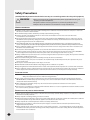
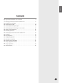
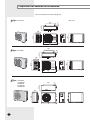
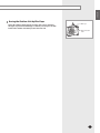
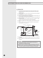
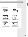
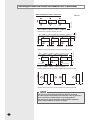
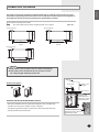
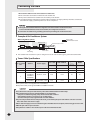
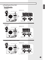
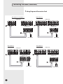
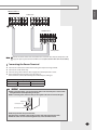
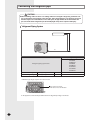
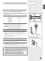
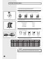
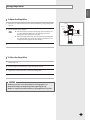
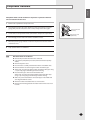
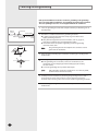
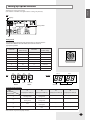
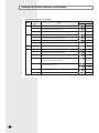
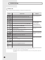
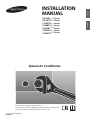
Safety Precautions (Carefully follow the precautions listed below because they are essential to guarantee the safety of the equipment.) WARNING • Always disconnect the air conditioner from the power supply before servicing it or accessing its internal components. • Verify that installation and testing operations are performed by qualified personnel. • Verify that the air conditioner is not installed in an easily accessible area. GENERAL INFORMATION Carefully read the content of this manual before installing the air conditioner and store the manual in a safe place in order to be able to use it as reference after installation. For maximum safety, installers should always carefully read the following warnings. Store the operation and installation manual in a safe location and remember to hand it over to the new owner if the air conditioner is sold or transferred. This manual explains how to install an indoor unit with a split system with two SAMSUNG units. The use of other types of units with different control systems may damage the units and invalidate the warranty. The manufacturer shall not be responsible for damages arising from the use of non compliant units. The manufacturer shall not be responsible for damage originating from unauthorized changes or the improper connection of electric and requirements set forth in the “Operating limits” table, included in the manual, shall immediately invalidate the warranty. The air conditioner should be used only for the applications for which it has been designed: the indoor unit is not suitable to be installed in areas used for laundry. Do not use the units if damaged. If problems occur, switch the unit off and disconnect it from the power supply. In order to prevent electric shocks, fires or injuries, always stop the unit, disable the protection switch and contact SAMSUNG’s technical support if the unit produces smoke, if the power cable is hot or damaged or if the unit is very noisy. Always remember to inspect the unit, electric connections, refrigerant tubes and protections regularly. These operations should be performed by qualified personnel only. The unit contains moving parts, which should always be kept out of the reach of children. Do not attempt to repair, move, alter or reinstall the unit. If performed by unauthorized personnel, these operations may cause electric shocks or fires. Do not place containers with liquids or other objects on the unit. All the materials used for the manufacture and packaging of the air conditioner are recyclable. The packing material and exhaust batteries of the remote control(optional) must be disposed of in accordance with current laws. The air conditioner contains a refrigerant that has to be disposed of as special waste. At the end of its life cycle, the air conditioner must be disposed of in authorized centers or returned to the retailer so that it can be disposed of correctly and safely. INSTALLING THE UNIT IMPORTANT: When installing the unit, always remember to connect first the refrigerant tubes, then the electrical lines. Always disassemble the electric lines before the refrigerant tubes. Upon receipt, inspect the product to verify that it has not been damaged during transport. If the product appears damaged, DO NOT INSTALL it and immediately report the damage to the carrier or retailer (if the installer or the authorized technician has collected the material from the retailer.) After completing the installation, always carry out a functional test and provide the instructions on how to operate the air conditioner to the user. Do not use the air conditioner in environments with hazardous substances or close to equipment that release free flames to avoid the occurrence of fires, explosions or injuries. POWER SUPPLY LINE, FUSE OR CIRCUIT BREAKER Always make sure that the power supply is compliant with current safety standards. Always install the air conditioner in compliance with current local safety standards. Always verify that a suitable grounding connection is available. Verify that the voltage and frequency of the power supply comply with the specifications and that the installed power is sufficient to ensure the operation of any other domestic appliance connected to the same electric lines. Always verify that the cut-off and protection switches are suitably dimensioned. Verify that the air conditioner is connected to the power supply in accordance with the instructions provided in the wiring diagram included in the manual. Always verify that electric connections (cable entry, section of leads, protections…) are compliant with the electric specifications and with the instructions provided in the wiring scheme. Always verify that all connections comply with the standards applicable to the installation of air conditioners. E-2 ENGLISH Contents Preparation for outdoor unit installation . . . . . . . . . . . . . . . . . . . . . . . . . . . . . . . . 4 Deciding on where to install the outdoor unit . . . . . . . . . . . . . . . . . . . . . . . . . 6 Outdoor unit installation . . . . . . . . . . . . . . . . . . . . . . . . . . . . . . . . . . . . . . . . . . . . . . . 9 Connecting the cable . . . . . . . . . . . . . . . . . . . . . . . . . . . . . . . . . . . . . . . . . . . . . . . . . 10 Connecting the refrigerant pipe . . . . . . . . . . . . . . . . . . . . . . . . . . . . . . . . . . . . . . 14 Connecting up and removing air in the circuit . . . . . . . . . . . . . . . . . . . . . . . . 15 Cutting / Flaring the pipes . . . . . . . . . . . . . . . . . . . . . . . . . . . . . . . . . . . . . . . . . . . . 16 Performing leak tests . . . . . . . . . . . . . . . . . . . . . . . . . . . . . . . . . . . . . . . . . . . . . . . . . 17 Connecting the drain hose to the outdoor unit . . . . . . . . . . . . . . . . . . . . . . . 18 Insulation . . . . . . . . . . . . . . . . . . . . . . . . . . . . . . . . . . . . . . . . . . . . . . . . . . . . . . . . . . . . . 18 Using stop valve . . . . . . . . . . . . . . . . . . . . . . . . . . . . . . . . . . . . . . . . . . . . . . . . . . . . . . 19 Long pipe application . . . . . . . . . . . . . . . . . . . . . . . . . . . . . . . . . . . . . . . . . . . . . . . . . 20 Pump down Procedure . . . . . . . . . . . . . . . . . . . . . . . . . . . . . . . . . . . . . . . . . . . . . . . 21 Checking correct grounding . . . . . . . . . . . . . . . . . . . . . . . . . . . . . . . . . . . . . . . . . . 22 Setting Up Option Switches . . . . . . . . . . . . . . . . . . . . . . . . . . . . . . . . . . . . . . . . . . 23 Testing Operations . . . . . . . . . . . . . . . . . . . . . . . . . . . . . . . . . . . . . . . . . . . . . . . . . . . . 25 Troubleshooting . . . . . . . . . . . . . . . . . . . . . . . . . . . . . . . . . . . . . . . . . . . . . . . . . . . . . . 26 E-3 Preparation for outdoor unit installation The air conditioner uses R22 refrigerant. 538 343 12 24.5 Unit : mm A Type: DC18ETSX1 548 530 265 543 12 343 B Type: FC18BTVX1 54.1 29 720 548 530 285 790 54.1 C Type: DH18BTX1 12 364 645 23 FC24BTVX1 DH24BTX1 CC24ETVX1 CC24BTVX1 638 310 880 E-4 54.1 ENGLISH Moving the Outdoor Unit by Wire Rope Fasten the outdoor unit by two 8m or longer wire ropes as shown at the figure. To prevent from damage or scratches, insert a piece of cloth between the outdoor unit and rope, then move the unit. Wire rope Plate protection cloth E-5 Deciding on where to install the outdoor unit Outdoor Unit The outdoor unit must not be placed on its side or upside down, as the compressor lubrication oil will run into the cooling circuit and seriously damage the unit. Choose a location that is dry and sunny, but not exposed to direct sunlight or strong winds. Do not block any passageways or thoroughfares. Choose a location where the noise of the air conditioner when running and the discharged air do not disturb any neighbours. Choose a position that enables the pipes and cables to be easily connected to the indoor unit. Install the outdoor unit on a flat, stable surface that can support its weight and does not generate any unnecessary noise and vibration. Position the outdoor unit so that the air flow is directed towards the open area. Maintain sufficient clearance around the outdoor unit, especially from a radio, computer, stereo system, etc. Indoor Unit Remote Control Stereo 1m or m ore 1m or more Fuse ore 1.5m or m Fuse re mo e or r m r mo 1.5 o m 1.5 1.5m re or mo Outdoor Unit If the outdoor unit is installed at a height, ensure that its base is firmly fixed in position. Make sure that the water dripping from the drain hose runs away correctly and safely. CAUTION You have just purchased a system air conditioner and it has been installed by your installation specialist. This device must be installed according to the national electrical rules. With an outdoor unit having net weight upper then 60kg, we suggest do not install it suspended on wall, but considering floor standing one. E-6 ENGLISH Space Requirements for Outdoor Unit When installing 1 outdoor unit 2000 or more 600 or more When 3 sides of the outdoor unit are blocked by the wall 1500 or more 300 or more The upper part of the outdoor unit and the air outlet is towards the wall 300 or more 300 or more 600 or more When the air outlet is towards the wall 1500 or more 300 or more When the air outlet is opposite the wall 1500 or more 300 or more Unit : mm The upper part of the outdoor unit and the air outlet is opposite the wall When front and rear side of the outdoor unit is towards the wall E-7 Deciding on where to install the outdoor unit (Continued) When installing more than 1 outdoor unit 1500 or more Unit : mm 300 or more When the air outlet is towards the wall 300 or more 600 or more 600 or more 600 or more 600 or more 600 or more 1500 or more 300 or more When 3 sides of the outdoor unit are blocked by the wall When front and rear side of the outdoor unit is towards the wall 1500 or more 600 or more 3000 or more 3000 or more 300 or more When front and rear side of the outdoor unit is towards the wall CAUTION The units must be installed according to distances declared, in order to permit accessibility from each side, either to guarantee correct operation of maintenance or repairing products. The unit’s parts must be reachable and removable completely under safety condition (for people or things). E-8 ENGLISH Outdoor unit installation The outdoor unit must be installed on a rigid and stable base to avoid any increase in the noise level and vibration, particularly if the outdoor unit is to be installed in a location exposed to strong winds or at a height, the unit must be fixed to an appropriate support(wall or ground). Fix the outdoor unit with anchor bolts. Note The anchor bolt must be 20mm or higher from the base surface. ��� ��� ��� ��� ��� Type B ��� Type A ��� ��� ��� ��� ��� Anchor bolt hole ��� Anchor bolt hole ��� Anchor bolt hole Unit : mm ��� ��� Type C CAUTION Make a drain outlet around the base for outdoor unit drainage. If the outdoor unit is installed on the roof, you have to check the ceiling strength and waterproof the unit. Outdoor Unit Outdoor Unit Support Outdoor Unit Support ���� Anchor bolt OUTDOOR UNIT INSTALLED ON THE WALL BY RACK - Ensure the wall will be able to suspend the weight of rack and outdoor unit; - Install the rack close to the column as much as possible; - Install proper grommet in order to reduce noise and residual vibration transferred by outdoor unit towards wall. Base Surface Designed to cut off residual vibration from outdoor unit to rack. (not supplied with product) Soft rubber designed to cut off vibration from rack to wall. (not supplied with product) E-9 Connecting the cable Two electronic cables must be connected to the outdoor unit. The connection cord between indoor unit and outdoor unit. The power cable between outdoor unit and auxiliary circuit breaker. Specially for Russian and European market, before installation, the supply authority should be consulted to determine the supply system impendance to ensure compliance. CAUTION During the unit installation make first refrigerant connections and then electrical connections. If unit is uninstalled first disconnect electrical cables, then refrigerant connections. Connect the air conditioner to grounding system before performing the electrical connection. Example of Air Conditioner System Power cable Communication cable When using ELB for 1 phase Outdoor Unit Communication cable 1Φ Power cable Grounding Indoor Unit If an outdoor unit is installed in a place in danger of an electric leak or submergence, you must install the ELB. Power Cable Specifications MAX. LENGTH mm²,wires m A A 1Φ, 220-240V~, 50Hz 2.5/2 < 10m 20 20 1Φ, 220V~, 60Hz 2.5/2 < 10m 20 20 DH18BTX1 FC24BTVX1 DH24BTX1 CC24BTVX1 1Φ, 220V~, 60Hz 2.5/2 < 10m 20 20 CC24ETVX1 1Φ, 220-240V~, 50Hz 2.5/2 < 10m 20 20 Outdoor A DC18ETSX1 B FC18BTVX1 C Type GL power cable 3Φ Type of outdoor unit 3Φ Power supply MCCB The power cable is not supplied with air conditioner. For power cable, use the grade H07RN-F or H05RN-F materials. CAUTION You should connect the power cable into the power cable terminal and fasten it with a clamp. The unbalanced power must be maintained within 2% of supply rating. - If the power is unbalanced greatly, it may shorten the life of the condenser. If the unbalanced power is exceeded over 4% of supply rating, the indoor unit is protected, stopped and the error mode indicates. To protect the product from water and possible shock, you should keep the power cable and the connection cord of the indoor and outdoor units in the iron pipe. Ensure that main supply connection is made through a switch that disconnects all poles, with contact gap of a least 3 mm. Must keep the cable in a protection tube. Keep distances of 50mm or more between power cable and communication cable. E-10 ENGLISH Wiring Diagram of Power Cable When using ELB for 1 phase FC18BTVX1 Power Supply MCCB Outdoor unit Electrical component box ELB 3(C) MCCB Cable clamp Communication cable &Connection cord Indoor Unit Main power cable DH18/24BTX1 Power Supply MCCB Outdoor unit Electrical component box ELB F1 F2 1(L) 2(L) MCCB Communication cable &Connection cord Indoor Unit Cable clamp Main power cable FC24BTVX1/CC24BTVX1/DC18ETSX1/CC24ETVX1 Power Supply MCCB Outdoor unit Electrical component box ELB 3(C) MCCB Indoor Unit Communication cable Main power cable &Connection cord Cable clamp E-11 Connecting the cable (Continued) Wiring Diagram of Connection Cord CC24ETV/CC24BTV DC18ETS Indoor unit 1(L) 2(N) 3(C) Indoor unit F1 F2 V1 V1 F3 F4 1(L) 2(N) 3(C) V1 Outdoor unit F4 3(C) Main power Main power FC18BTV FC24BTV Indoor unit Indoor unit F1 F2 V1 V2 Outdoor unit 3(C) 1(L) 2(N) 3(C) F1 F2 V1 V2 Outdoor unit 3(C) Main power E-12 F3 Outdoor unit 3(C) 1(L) 2(N) 3(C) V2 Main power ENGLISH DH18/24BT Indoor unit 1(L) 2(N) Vc Vc Vw Vw F1 F2 V1 V2 F3 F4 Outdoor unit F1 F2 1(L) 2(N) L N Main power Note Ground wire for the indoor unit and outdoor unit connection cable must be clamped to a soft copper tin-plated eyelet terminal with M4 screw hole(NOT SUPPLIED WITH UNIT ACCESSORIES). Connecting the Power Terminal Connect the cables to the terminal board using the compressed ring terminal. Connect the rated cables only. Connect using a driver which is able to apply the rated torque to the screws. If the terminal is loose, fire may occur caused by arc. If the terminal is connected too firmly, the terminal may be damaged. Tightening Torque (kgf • cm) M3 M4 5.9 30.0 1 phase 220V 3 phase 380V CAUTION When connecting cables, you can connect the cables to the electrical part or connect them through the holes below depending on the spot. When connecting cables, make the cable pass through the cable tube as shown at the figure. Cable tube Connection cord Communication cable Power cable Must keep the cable in a protection tube. Keep distances of 50mm or more between power cable and communication cable. When the cables are connected through the hole, remove the Plate bottom. E-13 Connecting the refrigerant pipe CAUTION When installing, make sure there is no leakage. When recovering the refrigerant, ground the compressor first before removing the connection pipe. If the refrigerant pipe is not properly connected and the compressor works with the service valve open, the pipe inhales the air and it makes the pressure inside of the refrigerant cycle abnormally high. It may cause explosion and injury. Refrigerant Piping System L1 H L0 Pipe length or height DH18BTX1 FC24BTVX1 DH24BTX1 CC24BTVX1 DC18ETSX1 FC18BTVX1 CC24ETVX1 Refrigerant piping system table Max. allowable length Actual pipe length L0 + H + L1 30m or less Allowable height length Actual pipe length H 15m or less Minimum pipe length: equal or more than 3 meters. Make at least one round: It will reduce noise and vibration The appearance of the unit may be different from the diagram depending on the model. E-14 ENGLISH Connecting up and removing air in the circuit The air in the indoor unit and in the pipe must be purged. If air remains in the refrigeration pipes, it will affect the compressor either reduce cooling/heating capacity or lead to a malfuction. Refrigerant for air purging is not charged in the outdoor unit. Use Vacuum Pump as shown at the right figure. 1 2 Connect each assembly pipe to the appropriate valve on the outdoor unit and tighten the flare nut. Referring to the illustration opposite, tighten the flare nut on section B first manually and then with a torque wrench, applying the following torque. Outer Diameter 6.35 mm(1/4”) 9.52 mm(3/8”) 12.70 mm(1/2”) 15.88 mm(5/8”) 19.05 mm(3/4”) 3 Torque (N•m) 18 42 55 65 100 Outdoor unit A C B D Connect the charging hose of low pressure side of manifold gauge to the packed valve having a service port as shown at the figure. CAUTION M ake the electrical connection and leave the system into “stand by mode”. Do not turn on the system. This is necessary to speed up vacuum operation (full OPEN position of Electronic Expansion Valve - EEV -). 4 Open the valve of the low pressure side of manifold gauge counterclockwise. 5 Purge the air from the system using vacuum pump for about 10 minutes. Close the valve of the low pressure side of manifold gauge clockwise. Make sure that pressure gauge shows -0.1MPa(-76cmHg) after about 10 minutes. This procedure is very important to avoid a gas leak. Turn off the vacuum pump. Remove the hose of the low pressure side of manifold gauge. 6 Set valve cork of both liquid side and gas side of packed valve to the open position. 7 Mount the valve stem nuts and the service port cap to the valve, and tighten them at the torque of 183kgf•cm with a torque wrench. 8 Check for gas leakage. At this time, especially check for gas leakage from the 3-way valve’s stem nuts(A port), and from the service port cap. Vacuum pump The designs and shape are subject to change according to the model. Stem cap A (gas) Valve stem B (liquid) CAUTION Connect the indoor and outdoor units using pipes with flared connections (not supplied). For the lines, use insulated, unwelded, degreased and deoxidized copper pipe,(Cu DHP type to ISO 1337), suitable for operating pressures of at least 4200kPa and for a burst pressure of at least 20700kPa. Copper pipe for hydro-sanitary applications is completely unsuitable. For sizing and limits (height difference, line length, max. bends, refrigerant charge, etc.) see “Connecting refrigerant pipe section”. E-15 Cutting/Flaring the pipes 1 Make sure that you have the required tools available. (pipe cutter, reamer, flaring tool and pipe holder) 2 If you wish to shorten the pipes, cut it with a pipe cutter, taking care to ensure that the cut edge remains at a 90° angle with the side of the pipe. Refer to the illustrations below for examples of edges cut correctly and incorrectly. Oblique Rough 3 To prevent any gas from leaking out, remove all burrs at the cut edge of the pipe, using aa reamer. 4 Slide a flare nut on to the pipe and modify the flare. Depth (A) Outer Diameter (D) 6.35 mm(1/4”) 9.52 mm(3/8”) 12.70 mm(1/2”) 15.88 mm(5/8”) 19.05 mm(3/4”) 5 6 Flare nut 1.3 mm 1.8 mm 2.0 mm 2.2 mm 2.2 mm Check that the flaring is correct, referring to the illustrations below for examples of incorrect flaring. Inclined Valve Burr Damaged Surface Cracked Uneven Thickness Align the pipes and tighten the flare nuts first manually and then with a torque wrench, applying the following torque. Valve cap Pressure port cap Valve needle Pressure port Wrench(mm) N•m Wrench(mm) N•m Wrench(mm) N•m Wrench(mm) N•m Wrench(mm) N•m 1/4" 3/8" 1/2" 5/8" 3/4" 17 22 26 29 36 18 42 55 65 100 23 23 29 29 38 20 20 40 40 40 18 18 18 18 18 16~18 16~18 16~18 16~18 16~18 Allen(hex.) 5 9 Allen(hex.) 5 9 Allen(hex.) 5 13 Allen(hex.) 5 13 Allen(hex.) 5 13 - 0.34 0.34 0.34 0.34 0.34 CAUTION In case of welding the pipe, you must weld with nitrogen gas blowing. E-16 ENGLISH Performing leak tests LEAK TEST WITH NITROGEN (before opening valves) In order to detect basic refrigerant leaks, before recreating the vacuum and recirculating the R22, it’s responsable of installer to pressurize the whole system with nitrogen (using a cylinder with pressure reducer) at a pressure above 30 bar (gauge). LEAK TEST WITH R22 (after opening valves) Before opening valves, discharge all the nitrogen into the system and create vacuum. After opening valves check leaks using a leak detector for refrigerant R22. Once you have completed all the connections, check for possible leaks using leak detector specifically designed for HFC refrigerants. To check for gas leaks on the... Then, using a leak detector, check the... Outdoor unit Valves on sections A and B. A B The designs and shape are subject to change according to the model. E-17 Connecting the drain hose to the outdoor unit When using the air conditioner in the heating mode, ice may accumulate . During de-icing (defrost operation), the condensed water must be drained off safely. Consequently, you must install a drain hose on the outdoor unit, following the instructions below. 50mm 30mm 1 Make space more than 50mm between the bottom of the outdoor unit and the ground for installation of the drain hose, as shown in figure. 2 Insert the drain plug into the hole on the underside of the outdoor unit. 3 Connect the drain hose to the drain plug. 4 Ensure that the drained water runs off correctly and safely. Insulation No gap Once you have checked that there are no leaks in the system, you can insulate the piping and hose. 1 NBR(T13.0 or thicker) E-18 To avoid condensation problems, place an insulator around each refrigerant pipe. Note When insulate the pipe, be sure to overlap the insulation. You have to use more than 120°C insulation(T13.0 or thicker Acrylonitrile Butadien Rubber) for the gas refrigerant pipe. ENGLISH Using stop valve To Open the Stop Valve 1 2 3 Cap Open the cap and turn the stop valve counterclockwise by using a hexagonal wrench. Turn it until the axis is stopped. Note Do not apply excessive force to the stop valve and always use special instruments. Otherwise, the stopping box can be damaged and the back sheet can leaks. If the watertight sheet leaks, turn the axis back by half, tighten the stopping box, then check the leakage again. If there is no leakage any more, tighten the axis entirely. Service port Axis Sealing point Tighten the cap securely. To Close the Stop Valve 1 Remove the cap. 2 Turn the stop valve clockwise by using a hexagonal wrench. 3 Tighten the axis until the valve reached the sealing point. 4 Tighten the cap securely. CAUTION When you use the service port, always use a charging hose, too. Check the leakage of refrigerant gas after tightening the cap. Must use a spanner and wrench when you open/tighten the stop valve. E-19 Long pipe application The outdoor unit is loaded with sufficient R22 refrigerant for 5 metres of piping. If you have used more than “5m”, add "A" of refrigerant for extra meter. (For maximum piping length and height, refer to page 14) The quantity of additional refrigerant is variable according to the installation situation. Thus, make sure the outdoor unit situation before adding refrigerant. This operation can only be performed by a qualified refrigeration specialist. Model Outdoor Unit Indoor Unit “A”(R22) FC24BTVX1 FC24BTVA1 15g/m CC24BTVX1 CC24BTVA1 25g/m DC18ETSX1 DC18ETSA1 25g/m CC24ETVX1 CC24ETVA1 25g/m DH18BTX1 DH18BTA1 35g/m DH24BTX1 DH24BTA1 15g/m FC18BTVX1 FC18BTVA1 15g/m Temper grade and minimum thickness of the refrigerant pipe Outer diameter [mm] Minimum thickness [mm] Ø6.35 0.7 Ø9.52 0.7 Ø12.70 0.8 Ø15.88 0.8 Ø19.05 0.9 Ø22.23 0.9 CAUTION E-20 Temper grade C1220T-O C1220T-1/2H OR C1220T-H • Make sure to use C1220T-1/2H (Semi-hard) pipe for more than Ø19.05mm. In case of using C1220T-O (Soft) pipe for Ø19.05mm, pipe may be broken, CAUTION oken, which can result in an injury. ENGLISH Pump down Procedure Pump down will be carried out when an evaporator is replaced or when the unit is relocated in another area. 1 Remove the cap from the low pressure side. 2 Turn the low pressure side valve clockwise to close and connect a pressure gauge (low pressure side) to the service valve, and open the valve again. 3 Set the unit to cool operation mode. (Check if the compressor is operating.) 4 Turn the high pressure side valve counter clockwise to close. 5 When the pressure gauge indicates “0” turn the low pressure side valve counter clockwise to close. 6 Stop operation of the air conditioner. 7 Close the each cap of valve. Note Low pressure side (Gas side) High pressure side (Liquide side) Relocation of the air conditioner Refer to this procedure when the unit is relocated. Carry out the pump down procedure (refer to the details of ‘pump down’). Remove the power cord. Disconnect the assembly cable from the indoor and outdoor units. Remove the flare nut connecting the indoor unit and the pipe. At this time, cover the pipe of the indoor unit and the other pipe using a cap or vinyl plug to avoid foreign material entering. Disconnect the pipe connected to the outdoor unit. At this time, cover the valve of the outdoor unit and the other pipe using a cap or vinyl plug to avoid foreign material entering. Make sure you do not bend the connection pipes in the middle and store together with the cables. Move the indoor and outdoor units to a new location. Remove the mounting plate for the indoor unit and move it to a new location. E-21 Checking correct grounding If the power distribution circuit does not have a grounding or the grounding does not comply with specifications, an grounding electrode must be installed. The corresponding accessories are not supplied with the air conditioner. Carbon plastic 1 Select an grounding electrode that complies with the specifications given in the illustration. 2 Determine a suitable location for the grounding electrode: In damp hard soil rather than loose sandy or gravel soil that has a higher grounding resistance Away from underground structures or facilities, such as gas pipes, water pipes, telephone lines and underground cables At least two metres away from a lightening conductor grounding electrode and its cable Steel core Terminal M4 PVC-insulated green/ yellow wire To grounding screw 50cm Note The grounding wire for the telephone line cannot be used to ground the air conditioner. 30cm 3 Finish wrapping insulating tape around the rest of the pipes leading to the outdoor unit. 4 Install a green/yellow coloured grounding wire: If the grounding wire is too short, connect an extension lead, in a mechanical way and wrapping it with insulating tape (do not bury the connection) Secure the grounding wire in position with staples Note E-22 If the grounding electrode is installed in an area of heavy traffic, its wire must be connected securely. 5 Carefully check the installation, by measuring the grounding resistance with a ground resistance tester. If the resistance is above required level, drive the electrode deeper into the ground or increase the number of grounding electrodes. 6 Connect the grounding wire to the electrical component box inside of the outdoor unit. Setting Up Option Switches ENGLISH Except for cooling only models (The outdoor unit PCB is not applied to the cooling only models) PCB Display Rotary switch KEY Rotary Switch You should display that how many indoor units are connected to the outdoor unit. Refer to the table below, then turn the arrow to appropriate position. KEY Switch No. Number of indoor unit(s) One 9 Nine Two A Ten Switch No. Number of indoor unit(s) 0 or 1 2 3 Three B Eleven 4 Four C Twelve 5 Five D Thirteen 6 Six E Fourteen 7 Seven F Fifteen 8 Eight - - K1 K2 K3 K4 DIS 1 DIS 2 Display CHECK MODE RESET DISPLAY MODE ITEM NO. CURRENT DATA DISPLAY Summary of KEY functions Function K1 (Displayed on SEG 3, 4) K2 (Displayed on SEG 3, 4) K3 (Displayed on SEG 3, 4) K4 (Displayed on SEG 3, 4) 1 Adding refrigerant at heating mode Adding refrigerant at cooling mode Reset Displays data 2 Test operation at heating mode Test operation at cooling mode - - 3 End Pump Down for recovery of refrigerant - - 4 - End - - Number of press times Use the K1 only for heat pump models. E-23 Setting up Option Switches (Continued) Reading data indicated on the display KEY Number of press K1 1 Adding refrigerant for heat pump models 2 Test operation for heat pump models 3 End 1 Adding refrigerant for cooling only models 2 Test operation for cooling only models 3 Pump Down for recovery of refrigerant 4 End K2 K3 K4 Item Reset 1 Discharge temperature of compressor 2 Temperature of outdoor heat exchanger 38 °C 3 Outdoor temperature 34 °C 4 Step of electronic expansion valve (0 step : all closed, 480 step : all open) 5 E-24 Example Display Meaning Temperature of evaporator 6 Indoor temperature 7 Stopping view mode & display communication data 110 °C 120STEP (12 x 10) -2 °C 12 °C 22 °C ENGLISH Testing Operations 1 Check the power supply between the outdoor unit and the auxiliary circuit breaker. Single phase power supply: L, N 2 Check the indoor unit. Check that you have connected the power and communication cables correctly. (If the power cable and communication cables one mixed up or connected incorrectly, the PCB will be damaged.) 3 If the outdoor unit is powered on, it will start tracking to check user's option(s) and number of indoor unit. - At this time, the SEG 1 and SEG 2 on outdoor unit PCB display the number of indoor unit registered and the SEG 3 and SEG 4 display the number of indoor units which responded. - If an error mode is displayed, fix the error according to the service manual. 4 Press K2 on the outdoor unit PCB. - If you press K2, the compressor starts operation. Operate the compressor for 20 minutes, then add refrigerant according to the pipe length. - If you press K2 again, test operation is started. - If you don't stop the operation of adding refrigerant, it will be stopped automatically after 1 hour. - If you don't stop test operation, it will be stopped automatically after 24 hours. - If K2 is pressed during the operation of adding refrigerant, test operation is started without compressor stopping. Therefore, start test operation after the operation of adding refrigerant. - The compressor can be operated after completely 3-minute preparation and tracking. - When testing operations at Heating Mode, press K1 instead of K2. 5 Check that indoor and outdoor temperatures, step of electronic expansion valve and operation of compressor by using the display mode(K4). 6 Check that there is any error mode in the outdoor unit PCB during the test. - You should test operations for more than 30 minutes. - Check that the water dripping from the drain hose runs away correctly and safely. 7 To complete the test, press the test operation KEY(K2) again. E-25 Troubleshooting Outdoor unit If an error occurs during the operation, it is displayed on the outdoor unit PCB. Display Explanation High temperature of Discharge (Protection control) High temperature of outdoor heat exchanger (Protection control) Remark Error about protection control of outdoor unit Reverse phase error (Protection control) COMP DOWN to protect being frozen In removing frost Error of Discharge TEMP sensor (OPEN/SHORT) Errors about outdoor unit sensor (OPEN/SHORT) Detection during the operation of indoor unit (Sensing and sending errors into the communication data) System Down caused by communication error after completion of tracking Communication and indoor unit errors Error of OUT TEMP sensor (OPEN/SHORT) Error of temperature sensor in outdoor heat exchanger (OPEN/SHORT) Mismatching of the indoor unit numbers set with those communicated after completion of tracking Error of float switch in indoor unit Error of setting option switches for optional accessories x OPEN/SHORT error of room sensor in indoor unit x x OPEN/SHORT error of eva in sensor in indoor unit Error of fan starting Self-diagnosis of indoor and outdoor unit (x:indoor unit address) Displays of operating status Open error of electronic expansion valve in outdoor unit (Detected once or more times) Close error of electronic expansion valve in outdoor unit (Detected once or more times) Flicker Flicker Below -5°C when cooling (Outdoor temperature) Over 30°C when heating (Outdoor temperature) K1, K2, K3, K4, K5 Flicker The order of priority : E1 E2 E5 P0 P1 P4 P5 P9 t1 t2 t3 tu to G4 G5 E3 qx rx vx K1, K2, K3, K4, K5 - In case that the same error displays from multi-indoor units, the one having the faster address has the priority. E-26 ENGLISH Memo E-27 Series DH18BT DC18ETSSeries FC18BTV Series FC24BTVSeries DH24BT Series CC24BTV Series CC24ETV Series System Air Conditioner This product is not manufactured for Iran. SVC Warranty will not be applicable and the user will be responsible for service expenses when the product is used in Iran. E S A DB98-31088A(1) ENGLISH ESPAÑOL INSTALLATION MANUAL