1
Cassette Type Series
4 Way cassette
Air Conditioner
user & installation manual
imagine the possibilities
Thank you for purchasing this Samsung product.
To receive more complete service, please
register your product at
www.samsung.com/register
E S P DB98-33760A(2)
Features of your new air conditioner
Cool Summer Offer
On those hot sweltering summer days and long restless nights, there is no better escape from the heat than the cool
comforts of home. Your new air conditioner brings an end to exhausting hot summer days and lets you rest. This summer,
beat the heat with your own air conditioner.
Cost Efficient System
Your new air conditioner not only provides maximum cooling power in the summer, but can also be an efficient heating
method in the winter with the advanced “Heat pump” system. This technology is up to 300% more efficient than electrical
heating, so you can further reduce its running cost. Now, meet year-round needs with one air conditioner.
A Look for Everywhere
The elegant and harmonious design gives priority to the esthetics of your space and complements any of your existing
interior décor. With its soft color and rounded-edge shape, the new air conditioner adds class to any room. Enjoy what your
air conditioner offers both functionally and esthetically.
Compact and easy-to-use Cassette type
Designed to be installed into most types of suspended ceiling, the cassette type air conditioner is ideal for business and
commercial accommodations. Fresh cool/warm air can be provided through the controllable 1, 2 or 4 sides of the unit. All
functions of the air conditioner will be controlled easily via a remote control.
2
Contents
USING PARTS
INSTALLATION PARTS
Safety precautions . . . . . . . . . . . . . . . . . . . . . . . . . . . . . . . . . . . . . . . . . . . . . . . . . . . . . . . . . . . . . . . . . . . . . . . . . . . . . . . . . . . . . . . . . . . . . . . . . . . . . . . . . 16
Preparation for installation . . . . . . . . . . . . . . . . . . . . . . . . . . . . . . . . . . . . . . . . . . . . . . . . . . . . . . . . . . . . . . . . . . . . . . . . . . . . . . . . . . . . . . . . . . . . . . . . . 18
Deciding on where to install the indoor unit . . . . . . . . . . . . . . . . . . . . . . . . . . . . . . . . . . . . . . . . . . . . . . . . . . . . . . . . . . . . . . . . . . . . . . . . . . . . . . . 18
Indoor unit installation . . . . . . . . . . . . . . . . . . . . . . . . . . . . . . . . . . . . . . . . . . . . . . . . . . . . . . . . . . . . . . . . . . . . . . . . . . . . . . . . . . . . . . . . . . . . . . . . . . . . 21
Purging the unit . . . . . . . . . . . . . . . . . . . . . . . . . . . . . . . . . . . . . . . . . . . . . . . . . . . . . . . . . . . . . . . . . . . . . . . . . . . . . . . . . . . . . . . . . . . . . . . . . . . . . . . . . . . 22
Connecting the refrigerant pipe . . . . . . . . . . . . . . . . . . . . . . . . . . . . . . . . . . . . . . . . . . . . . . . . . . . . . . . . . . . . . . . . . . . . . . . . . . . . . . . . . . . . . . . . . . . 22
Cutting/flaring the pipes . . . . . . . . . . . . . . . . . . . . . . . . . . . . . . . . . . . . . . . . . . . . . . . . . . . . . . . . . . . . . . . . . . . . . . . . . . . . . . . . . . . . . . . . . . . . . . . . . . . 23
Performing leak test & insulation . . . . . . . . . . . . . . . . . . . . . . . . . . . . . . . . . . . . . . . . . . . . . . . . . . . . . . . . . . . . . . . . . . . . . . . . . . . . . . . . . . . . . . . . . . . 24
Drainpipe and drain hose installation . . . . . . . . . . . . . . . . . . . . . . . . . . . . . . . . . . . . . . . . . . . . . . . . . . . . . . . . . . . . . . . . . . . . . . . . . . . . . . . . . . . . . . 26
Installing DPM . . . . . . . . . . . . . . . . . . . . . . . . . . . . . . . . . . . . . . . . . . . . . . . . . . . . . . . . . . . . . . . . . . . . . . . . . . . . . . . . . . . . . . . . . . . . . . . . . . . . . . . . . . . . . 28
Connecting the connection cord . . . . . . . . . . . . . . . . . . . . . . . . . . . . . . . . . . . . . . . . . . . . . . . . . . . . . . . . . . . . . . . . . . . . . . . . . . . . . . . . . . . . . . . . . . . 29
Setting an indoor unit address and installation option . . . . . . . . . . . . . . . . . . . . . . . . . . . . . . . . . . . . . . . . . . . . . . . . . . . . . . . . . . . . . . . . . . . . . . 32
Troubleshooting . . . . . . . . . . . . . . . . . . . . . . . . . . . . . . . . . . . . . . . . . . . . . . . . . . . . . . . . . . . . . . . . . . . . . . . . . . . . . . . . . . . . . . . . . . . . . . . . . . . . . . . . . . . 39
3
ENGLISH
Safety precautions . . . . . . . . . . . . . . . . . . . . . . . . . . . . . . . . . . . . . . . . . . . . . . . . . . . . . . . . . . . . . . . . . . . . . . . . . . . . . . . . . . . . . . . . . . . . . . . . . . . . . . . . . . 4
Viewing the parts . . . . . . . . . . . . . . . . . . . . . . . . . . . . . . . . . . . . . . . . . . . . . . . . . . . . . . . . . . . . . . . . . . . . . . . . . . . . . . . . . . . . . . . . . . . . . . . . . . . . . . . . . . . 8
Using your air conditioner . . . . . . . . . . . . . . . . . . . . . . . . . . . . . . . . . . . . . . . . . . . . . . . . . . . . . . . . . . . . . . . . . . . . . . . . . . . . . . . . . . . . . . . . . . . . . . . . . . 9
Cleaning and maintaining the air conditioner . . . . . . . . . . . . . . . . . . . . . . . . . . . . . . . . . . . . . . . . . . . . . . . . . . . . . . . . . . . . . . . . . . . . . . . . . . . . . . 10
Appendix . . . . . . . . . . . . . . . . . . . . . . . . . . . . . . . . . . . . . . . . . . . . . . . . . . . . . . . . . . . . . . . . . . . . . . . . . . . . . . . . . . . . . . . . . . . . . . . . . . . . . . . . . . . . . . . . . . 14
USING PARTS
Safety precautions
Before using your new air conditioner, please read this manual thoroughly to ensure that you know how to safely and
efficiently operate the extensive features and functions of your new appliance.
Because the following operating instructions cover various models, the characteristics of your air conditioner may differ
slightly from those described in this manual. If you have any questions, call your nearest contact center or find help and
information online at www.samsung.com.
Important safety symbols and precautions:
WARNING
Hazards or unsafe practices that may result in severe personal injury or death.
CAUTION
Hazards or unsafe practices that may result in minor personal injury or property damage.
Follow directions.
Do NOT attempt.
Make sure the machine is grounded to prevent electric shock.
Unplug the power plug from the wall socket.
Do NOT disassemble.
FOR INSTALLATION
WARNING
Use the power line with the power specifications of the product or higher and use the power line for this
appliance only. In addition, do not use an extension line.
XXExtending the power line may result in electric shock or fire.
XXDo not use an electric transformer. It may result in electric shock or fire.
XXIf the voltage/frequency/rated current condition is different, it may cause fire.
The installation of this appliance must be performed by a qualified technician or service company.
XXFailing to do so may result in electric shock, fire, explosion, problems with the product, or injury.
Install a switch and circuit breaker dedicated to the air conditioner.
XXFailing to do so may result in electric shock or fire.
Fix the outdoor unit firmly so that the electric part of the outdoor unit is not exposed.
XXFailing to do so may result in electric shock or fire.
Do not install this appliance near a heater, inflammable material. Do not install this appliance in a humid, oily
or dusty location, in a location exposed to direct sunlight and water (rain drops). Do not install this appliance in
a location where gas may leak.
XXThis may result in electric shock or fire.
Never install the outdoor unit in a location such as on a high external wall where it could fall.
XXIf the outdoor unit falls, it may result in injury, death or property damage.
This appliance must be properly grounded. Do not ground the appliance to a gas pipe, plastic water pipe,
or telephone line.
XXFailure to do so may result in electric shock, fire, an explosion, or other problems with the product.
XXNever plug the power cord into a socket that is not grounded correctly and make sure that it is in accordance
with local and national codes.
4
FOR INSTALLATION
CAUTION
FOR POWER SUPPLY
ENGLISH
Install your appliance on a level and hard floor that can support its weight.
XXFailing to do so may result in abnormal vibrations, noise, or problems with the product.
Install the draining hose properly so that water is drained correctly.
XXFailing to do so may result in water overflowing and property damage.
When installing the outdoor unit, make sure to connect the draining hose so that draining is performed
correctly.
XXThe water generated during the heating operation by the outdoor unit may overflow and result in property
damage.
In particular, in winter, if a block of ice falls, it may result in injury, death or property damage.
WARNING
When the circuit breaker is damaged, contact your nearest service center.
Do not pull or excessively bend the power line. Do not twist or tie the power line. Do not hook the power line
over a metal object, place a heavy object on the power line, insert the power line between objects, or push the
power line into the space behind the appliance.
XXThis may result in electric shock or fire.
FOR POWER SUPPLY
CAUTION
When not using the air conditioner for a long period of time or during a thunder/lightning storm, cut the
power at the circuit breaker.
XXFailing to do so may result in electric shock or fire.
FOR USING
WARNING
If the appliance is flooded, please contact your nearest service center.
XXFailing to do so may result in electric shock or fire.
If the appliance generates a strange noise, a burning smell or smoke, unplug the power plug immediately and
contact your nearest service center.
XXFailing to do so may result in electric shock or fire.
In the event of a gas leak (such as propane gas, LP gas, etc.), ventilate immediately without touching the power
line.
Do not touch the appliance or power line.
XXDo not use a ventilating fan.
XXA spark may result in an explosion or fire.
To reinstall the air conditioner, please contact your nearest service center.
XXFailing to do so may result in problems with the product, water leakage, electric shock, or fire.
XXA delivery service for the product is not provided. If you reinstall the product in another location, additional
construction expenses and an installation fee will be charged.
XXEspecially, when you wish to install the product in an unusual location such as in an industrial area or near the
seaside where it is exposed to the salt in the air, please contact your nearest service center.
5
Safety precautions
FOR USING
WARNING
Do not touch the circuit breaker with wet hands.
XXThis may result in electric shock.
Do not strike or pull the air conditioner with excessive force.
XXThis may result in fire, injury, or problems with the product.
Do not place an object near the outdoor unit that allows children to climb onto the machine.
XXThis may result in children seriously injuring themselves.
Do not turn the air conditioner off with the circuit breaker while it is operating.
XXTurning the air conditioner off and then on again with the circuit breaker may cause a spark and result in electric
shock or fire.
After unpacking the air conditioner, keep all packaging materials well out of the reach of children, as
packaging materials can be dangerous to children.
XXIf a child places a bag over its head, it may result in suffocation.
Do not insert your fingers or foreign substances into the outlet when the air conditioner is operating or the
front panel is closing.
XXTake special care that children do not injure themselves by inserting their fingers into the product.
Do not touch the front panel with your hands or fingers during the heating operation.
XXThis may result in electric shock or burns.
Do not insert your fingers or foreign substances into the air inlet/outlet of the air conditioner.
XXTake special care that children do not injure themselves by inserting their fingers into the product.
Do not use this air conditioner for long periods of time in badly ventilated locations or near infirm people.
XXSince this may be dangerous due to a lack of oxygen, open a window at least once an hour.
If any foreign substance such as water has entered the appliance, cut the power by unplugging the power plug
and turning the circuit breaker off and then contact your nearest service center.
XXFailing to do so may result in electric shock or fire.
Do not attempt to repair, disassemble, or modify the appliance yourself.
XXDo not use any fuse (such as cooper, steel wire, etc.)other than the standard fuse.
XXFailing to do so may result in electric shock, fire, problems with the product, or injury.
FOR USING
CAUTION
Do not place objects or devices under the indoor unit.
XXWater dripping from the indoor unit may result in fire or property damage.
Check that the installation frame of the outdoor unit is not broken at least once a year.
XXFailing to do so may result in injury, death or property damage.
Max current is measured according to IEC standard for safety and current is measured according to ISO
standard for energy efficiency.
6
FOR CLEANING
ENGLISH
Do not stand on top of the appliance or place objects (such as laundry, lighted candles, lighted cigarettes,
dishes, chemicals, metal objects, etc.) on the appliance.
XXThis may result in electric shock, fire, problems with the product, or injury.
Do not operate the appliance with wet hands.
XXThis may result in electric shock.
Do not spray volatile material such as insecticide onto the surface of the appliance.
XXAs well as being harmful to humans, it may also result in electric shock, fire or problems with the product.
Do not drink the water from the air conditioner.
XXThe water may be harmful to humans.
Do not apply a strong impact to the remote controller and do not disassemble the remote controller.
Do not touch the pipes connected with the product.
XXThis may result in burns or injury.
Do not use this air conditioner to preserve precision equipment, food, animals, plants or cosmetics, or for any
other unusual purposes.
XXThis may result in property damage.
Avoid directly exposing humans, animals or plants from the air flow from the air conditioner for long periods
of time.
XXThis may result in harm to humans, animals or plants.
This appliance is not intended for use by persons (including children) with reduced physical, sensory or mental
capabilities, or lack of experience and knowledge, unless they have been given supervision or instruction
concerning use of the appliance by a person responsible for their safety. Children should be supervised to
ensure that they do not play with the appliance.
WARNING
Do not clean the appliance by spraying water directly onto it. Do not use benzene, thinner or alcohol to clean
the appliance.
XXThis may result in discoloration, deformation, damage, electric shock or fire.
Before cleaning or performing maintenance, unplug the air conditioner from the wall socket and wait until the
fan stops.
XXFailing to do so may result in electric shock or fire.
FOR CLEANING
CAUTION
Take care when cleaning the surface of the heat exchanger of the outdoor unit since it has sharp edges.
XXTo avoid cutting your fingers, wear thick cotton gloves when cleaning it.
Do not clean the inside of the air conditioner by yourself.
XXFor cleaning inside the appliance, contact your nearest service center.
XXWhen cleaning the internal filter, refer to the descriptions in the ‘Cleaning and maintaining the air conditioner’
section.
XXFailure to do may result in damage, electric shock or fire.
7
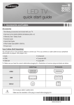
Viewing the parts
Main parts
Air flow blade
Air intake
Air filter (under the grille)
Display
Indicator
Remote control sensor
Filter reset indicator
Timer indicator
Removing frost indicator
On/Off operation indicator
NOTE
8
• Your air conditioner and display may look slightly different from the illustration shown above depending on your
model.
Using your air conditioner
Tips on using air conditioner
Here are some tips that you would follow when using your air conditioner.
RECOMMENDATION
Cooling
• If current outside temperatures are much higher than the selected indoor temperature, it
may take time to bring the inner temperature to the desired coolness.
• Avoid drastically turning down the temperature. Energy is wasted and the room does not
cool faster.
Heating
• Since the air conditioner heats the room by taking heat energy from outdoor air, the
heating capacity may decrease when outdoor temperatures are extremely low. If you
feel the air conditioner insufficiently heats, using an additional heating appliance in
combination with the air conditioner is recommended.
Frost & De-ice
• When the air conditioner runs in Heat mode, due to temperature difference between the
unit and the outside air, frost will form.
• If this happens:
-- The air conditioner stops heating.
-- The air conditioner will operate automatically in De-ice mode for 10 minutes.
-- The steam produced on the outdoor unit in De-ice mode is safe.
• No intervention is required; after about 10 minutes, the air conditioner operates again
normally.
NOTE
• The unit will not operate when it starts to de-ice.
Fan
XXFan may not operate for about 3~5 minutes at the beginning to prevent any cold blasts
while the air conditioner is warming up.
High indoor/outdoor
temperatures
XXIf both indoor and outdoor temperatures are high and the air conditioner is running in
Heat mode, the outdoor unit’s fan and compressor may stop at times. This is normal;
wait until the air conditioner turns on again.
Power failure
XXIf a power failure occurs during the operation of the air conditioner, the operating
immediately stops and unit will be off. When power returns, the air conditioner will run
automatically.
Protection mechanism
XXIf the air conditioner has just been turned on after operation stops or being plugged
in, cool/warm air does not come out for 3 minutes to protect the compressor of the
outdoor unit.
9
ENGLISH
TOPIC
Cleaning and maintaining the air conditioner
Cleaning the exterior
Wipe the surface of the unit with a slightly wet or dry cloth when needed.
Wipe off dirt of odd-shaped area by using a soft brush.
CAUTION
10
• Do not use Benzene or Thinner.
They may damage the surface of the air conditioner and can create
a risk of fire.
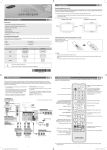
Cleaning air filter and grille
Clean the grille and Air filter with a vacuum cleaner
or soft brush. If dust is too heavy, then rinse it with
running water and dry it in a ventilated area.
• For best conditions, repeat every two weeks.
• If the Air filter dries in a confined (or humid) area,
odors may generate. If it occurs, re-clean and dry it in
a well-ventilated area.
Insert the Air filter back in its original position.
• You will hear a click sound when the Air filter is
properly placed.
NOTE
Detach the front grille.
• Remove the safety clip first and then remove the
hinge. Pull the green switch on the hinge part
down and then press and pull the hinge part to
remove the grillae. (There are two hinges on the
grille and you must apply this step on both of
them to remove the grille.)
❋❋ If you want to clean the filter only, you do not
have to detach the grille. Follow step 4 and 5
ENGLISH
Open the front grille.
• Open the blades on the left and right side of the
Samsung logo. Press both of the levers and pull the
grille downward. Two safety clips are mounted to the
front grille to prevent it from dropping.
Pull out the Air filter.
Attach the front grille.
• Reverse the above steps to attach the front grille.
• The illustration shown above may differ from yours depending on your model.
• After cleaning the filter, press the Filter Reset button on the remote control for 2 seconds to reset the filter
schedule. Filter sign indicator will be on for cleaning time.
• If the angle on the air flow blades has been changed by user due to opening the front grille for installation
or maintenance, you must turn off the circuit breaker and turn it on again before using the air conditioner.
Otherwise, angles of the each angle can be different or some of the blade may not close when the product is off.
11
Cleaning and maintaining the air conditioner
Maintaining your air conditioner
If the air conditioner will not be used for an extended period of time, dry the air conditioner to maintain it in best condition.
1. Dry the air conditioner thoroughly by operating in Fan mode for 3 to 4 hours and disconnect the power plug. There may
be internal damage if moisture is left in components.
2. Before using the air conditioner again, dry the inner components of the air conditioner again by running in Fan mode for
3 to 4 hours. This helps remove odors which may have generated from dampness.
Periodical checks
Refer to the following chart to maintain the air conditioner properly.
Type
Description
Clean the air filter (1)
Indoor unit
Monthly
Every 4
months
●
Clean the condensate drain pan (2)
●
Thoroughly clean the heat exchanger (2)
●
Clean the condensate drain pipe (2)
●
Replace the remote control batteries (1)
Clean the heat exchanger on the outside of the unit (2)
Outdoor unit
NOTE
12
Once a year
●
●
Clean the heat exchanger on the inside of
the unit (2)
●
Clean the electric components with jets of
air (2)
●
Verify that all the electric components are firmly
tightened (2)
●
Clean the fan (2)
●
Verify that all the fan assembly is firmly
tightened (2)
●
Clean the condensate drain pan (2)
●
• The checks and maintenance operations described are essential to guarantee the efficiency of the air
conditioner. The frequency of these operations varies according to the characteristics of the area, the amount of
dust, etc.
-- The described operations should be performed more frequently if the area of installation is very dusty.
-- These operations must always be performed by qualified personnel. For more detailed information, see the
Installation Manual.
Internal protections via the unit control system
This internal protection operates if an internal fault occurs in the air conditioner.
Type
Description
The internal fan will be off to against cold air when the heat pump is heating.
De-ice cycle
The internal fan will be off to against cold air when the heat pump is heating.
ENGLISH
Against cold air
Anti-protection of internal
battery
The compressor will be off to protect internal battery when the air conditioner operates
in Cool mode.
Protect compressor
The air conditioner does not start operating immediately to protect the compressor of
the outdoor unit after it has been started.
NOTE
• If the heat pump is operating in Heat mode, De-ice cycle is actuated to remove frost from an outdoor unit that
may have deposited at low temperatures.
• The internal fan is switched off automatically and restarted only after the de-ice cycle is completed.
13
Appendix
Troubleshooting
Refer to the following chart if the air conditioner operates abnormally. This may save time and unnecessary expenses.
PROBLEM
SOLUTION
The air conditioner does not
operate immediately after it has
been restarted.
• Because of the protective mechanism, the appliance does not start operating
immediately to keep the unit from overloading.
The air conditioner will start in 3 minutes.
The air conditioner does not
work at all.
• Check that the power plug is properly connected. Insert the power plug into the wall
socket correctly.
• Check if the circuit breaker is switched off.
• Check if there is a power failure.
• Check your fuse. Make sure it is not blown out.
The temperature does not
change.
• Check if you selected Fan mode.
Press the Mode button on the remote control to select another mode.
The cool (warm) air does not
come out of the air conditioner.
• Check if the set temperature is higher (lower) than the current temperature. Press the
Temperature button on the remote control to change the set temperature. Press the
Temperature button to decrease or increase the temperature.
• Check if the air filter is blocked by dirt. Clean the air filter every two weeks.
• Check if the air conditioner has just been turned on. If so, wait 3 minutes. Cool air
does not come out to protect the compressor of the outdoor unit.
• Check if the air conditioner is installed in a place with a direct exposure to sunlight.
Hang curtains on windows to boost cooling efficiency.
• Check if the cover or any obstacle is not near the outdoor unit.
• Check if the refrigerant pipe is too long.
• Check if the air conditioner is only available in Cool mode.
• Check if the remote control is only available for cooling model.
The fan speed does not change.
• Check if you selected Auto or Dry mode.
The air conditioner automatically adjusts the fan speed to Auto in Auto/Dry mode.
Timer function does not set.
• Check if you press the Power button on the remote control after you have set the
time.
Odors permeate in the room
during operation.
• Check if the appliance is running in a smoky area or if there is a smell entering from
outside. Operate the air conditioner in Fan mode or open the windows to air out the
room.
The air conditioner makes a
bubbling sound.
• A bubbling sound may be heard when the refrigerant is circulating through the
compressor. Let the air conditioner operate in a selected mode.
• When you press the Power button on the remote control, noise may be heard from
the drain pump inside the air conditioner.
Water is dripping from the air
flow blades.
• Check if the air conditioner has been cooling for an extended period of time with
the air flow blades pointed downwards. Condensation may generate due to the
difference in temperature.
14
PROBLEM
SOLUTION
The air conditioner does not
turn on or off with the wired
remote control.
• Check if you set the wired remote control for group control.
The wired remote control does
not operate.
• Check if TEST indicator is displayed on the wired remote control. If so, turn off the unit
and switch off the circuit breaker. Call your nearest contact center.
The indicators of the digital
display flashes.
• Press the Power button on the remote control to turn the unit off and switch the
circuit breaker off. Then, switch it on again.
Operation ranges
The table below indicates the temperature and humidity ranges the air conditioner can be operated within. Refer to the table
for efficient use.
MODE
OUTDOOR TEMPERATURE
INDOOR TEMPERATURE
INDOOR HUMIDITY
REMARKS
COOLING
-5°C/23°F to 43°C/109°F
18°C/64°F to 32°C/90°F
80% or less
-
HEATING
-20°C/-4°F to 24°C/75°F
27°C/81°F or less
-
-
DRYING
-5°C/23°F to 43°C/109°F
18°C/64°F to 32°C/90°F
-
-
NOTE
• The standardized temperature for heating is 7˚C/45˚F. If the outdoor temperature drops to 0˚C/32˚F or below,
the heating capacity can be reduced depending on the temperature condition.
If the cooling operation is used at over 32˚C/90˚F (indoor temperature), it does not cool at its full capacity.
15
ENGLISH
Remote control is not working.
• Check if your batteries are depleted.
• Make sure batteries are correctly installed.
• Make sure nothing is blocking your remote control sensor.
• Check that there are strong lighting apparatus near the air conditioner. Strong light
which comes from fluorescent bulbs or neon signs may interrupt the electric waves.
INSTALLATION PARTS
Safety precautions
Carefully follow the precautions listed below because they are essential to guarantee the safety of the equipment.
WARNING
• Always disconnect the air conditioner from the power supply before servicing it or
accessing its internal components.
• Verify that installation and testing operations are performed by qualified personnel.
• Verify that the air conditioner is not installed in an easily accessible area.
General information
XXCarefully read the content of this manual before installing the air conditioner and store the manual in a safe place in order
to be able to use it as reference after installation.
XXFor maximum safety, installers should always carefully read the following warnings.
XXStore the operation and installation manual in a safe location and remember to hand it over to the new owner if the air
conditioner is sold or transferred.
XXThis manual explains how to install an indoor unit with a split system with two SAMSUNG units. The use of other types
of units with different control systems may damage the units and invalidate the warranty. The manufacturer shall not be
responsible for damages arising from the use of non compliant units.
XXThe air conditioner is compliant with the requirements of the Low Voltage Directive (72/23/EEC),
the EMC Directive (89/336/EEC) and the Directive on pressurized equipment (97/23/EEC).
XXThe manufacturer shall not be responsible for damage originating from unauthorized changes or the improper
connection of electric and requirements set forth in the “Operating limits” table, included in the manual. Making such
changes or improper connections may damage the units and invalidate the warranty.
XXThe air conditioner should be used only for the applications for which it has been designed: the indoor unit is not suitable
to be installed in areas used for laundry.
XXDo not use the units if damaged. If problems occur, switch the unit off and disconnect it from the power supply.
XXIn order to prevent electric shocks, fires or injuries, always stop the unit, disable the protection switch and contact
SAMSUNG’s technical support if the unit produces smoke, if the power cable is hot or damaged or if the unit is very noisy.
XXAlways remember to inspect the unit, electric connections, refrigerant tubes and protections regularly. These operations
should be performed by qualified personnel only.
XXThe unit contains moving parts, which should always be kept out of the reach of children.
XXDo not attempt to repair, move, alter or reinstall the unit. If performed by unauthorized personnel, these operations may
cause electric shocks or fires.
XXDo not place containers with liquids or other objects on the unit.
XXAll the materials used for the manufacture and packaging of the air conditioner are recyclable.
XXThe packing material and exhaust batteries of the remote controller(optional) must be disposed of in accordance with
current laws.
XXThe air conditioner contains a refrigerant that has to be disposed of as special waste. At the end of its life cycle, the air
conditioner must be disposed of in authorized centers or returned to the retailer so that it can be disposed of correctly
and safely.
Installing the unit
IMPORTANT: When installing the unit, always remember to connect first the refrigerant tubes, then the electrical lines. Always
disassemble the electric lines before the refrigerant tubes.
XXUpon receipt, inspect the product to verify that it has not been damaged during transport. If the product appears
damaged, DO NOT INSTALL it and immediately report the damage to the carrier or retailer (if the installer or the
authorized technician has collected the material from the retailer.)
XXAfter completing the installation, always carry out a functional test and provide the instructions on how to operate the air
conditioner to the user.
XXDo not use the air conditioner in environments with hazardous substances or close to equipment that release free flames
to avoid the occurrence of fires, explosions or injuries.
16
XXOur units should be installed in compliance with the spaces shown in the installation manual, to ensure accessibility from
both sides and allow repairs or maintenance operations to be carried out. The unit’s components should be accessible
and easy to disassemble without endangering people and objects.
XXFor this reason, when provisions of the installation manual are not complied with, the cost required to access and repair
the units (in SAFETY CONDITIONS, as set out in prevailing regulations) with harnesses, ladders, scaffolding or any other
elevation system will NOT be considered part of the warranty and will be charged to the end customer.
XXAlways make sure that the power supply is compliant with current safety standards. Always install the air conditioner in
compliance with current local safety standards.
XXAlways verify that a suitable grounding connection is available.
XXVerify that the voltage and frequency of the power supply comply with the specifications and that the installed power is
sufficient to ensure the operation of any other domestic appliance connected to the same electric lines.
XXAlways verify that the cut-off and protection switches are suitably dimensioned.
XXVerify that the air conditioner is connected to the power supply in accordance with the instructions provided in the
wiring diagram included in the manual.
XXAlways verify that electric connections (cable entry, section of leads, protections…) are compliant with the electric
specifications and with the instructions provided in the wiring scheme. Always verify that all connections comply with
the standards applicable to the installation of air conditioners.
XXDevices disconnected from the power supply should be completely disconnected in the condition of overvoltage
category.
CAUTION
• Make sure that you earth the cables.
-- Do not connect the earth wire to the gas pipe, water pipe, lighting rod or telephone wire. If earthing is not
complete, electric shock or fire may occur.
• Install the circuit breaker.
-- If the circuit breaker is not installed, electric shock or fire may occur.
• Make sure that the condensed water dripping from the drain hose runs out properly and safely.
• Install the power cable and communication cable of the indoor and outdoor unit at least 1m away from the
electric appliance.
• Install the indoor unit away from lighting apparatus using the ballast.
-- If you use the wireless remote control, reception error may occur due to the ballast of the lighting apparatus.
• Do not install the air conditioner in following places.
-- Place where there is mineral oil or arsenic acid. Resin parts flame and the accessories may drop or water may
leak. The capacity of the heat exchanger may reduce or the air conditioner may be out of order.
-- The place where corrosive gas such as sulfurous acid gas generates from the vent pipe or air outlet.
-- The copper pipe or connection pipe may corrode and refrigerant may leak.
-- The place where there is a machine that generates electromagnetic waves. The air conditioner may not
operate normally due to control system.
-- The place where there is a danger of existing combustible gas, carbon fiber or flammable dust.
-- The place where thinner or gasoline is handled. Gas may leak and it may cause fire.
17
ENGLISH
Power supply line, fuse or circuit breaker
Preparation for installation
When deciding on the location of the air conditioner with the owner, the following restrictions must be taken into account.
General
Do NOT install the air conditioner in a location where it will come into contact with the following elements :
XXCombustible gases
XXSaline air
XXMachine oil
XXSulphide gas
XXSpecial environmental conditions
If you must install the unit in such conditions, first consult your dealer.
Avoid installing the air conditioner :
XXIn areas where it is exposed to direct sunlight. Close to heat sources.
XXIn damp areas or locations where it could come into contact with water. (for example rooms used for laundry)
XXIn areas where curtains and furniture could affect the supply and discharge of air.
XXWithout leaving the required minimum space around the unit. (as shown in the drawing)
XXIn scarcely ventilated areas.
XXOn surfaces that are unable to support the weight of the unit without deforming, breaking or causing vibrations during
the use of the air conditioner.
XXIn a position that does not enable the condensate drainage pipe to be correctly installed. (at the end of the installation. It
is always essential to check the efficiency of the drainage system)
Accessories
XXThe following accessories are supplied with the indoor unit.
The type and quantity may differ depending on the specifications.
Insulation cover
band
Insulation pipe
Cable-tie
Drain hose
Installation manual
Clamp
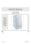
Deciding on where to install the indoor unit
Indoor unit
XXThere must be no obstacles near the air inlet and outlet.
XXInstall the indoor unit on a ceiling that can support its weight.
XXMaintain sufficient clearance around the indoor unit.
XXMake sure that the water dripping from the drain hose runs away correctly and safely.
XXThe indoor unit must be installed in this way, that they are out of public access. (Not touchable by the users)
CAUTION
18
• If you install the cassette type indoor unit on the ceiling with humidity over 80%, you must apply extra 10mm of
polyethylene foam or other insulation with similar material on the body of the indoor unit.
Space requirements for indoor unit
ore
m or m
1500m
or
mo
re
15
00
mm
ENGLISH
15
00
mm
or
mo
re
ore
m or m
1500m
CAUTION
• The units must be installed according to distances declared, in order to permit accessibility from each side, either
to guarantee correct operation of maintenance or repairing products.
The unit’s parts must be reachable and removable completely under safety condition (for people or things).
• Do not hold the discharge while carrying the indoor unit to avoid the possibility of breakage. You must hold the
hanger plate on the corner and carry the indoor unit.
Required space for an indoor unit installation
1500mm
or more
‘C’ mm
2500mm or more
17mm
20mm
Obstruction
ND0524H✴✴/ND0564H✴✴
ND0604H✴✴/ND0714H✴✴
ND0724H✴✴/ND0834H✴✴
ND0904H✴✴/ND1004H✴✴
MODEL
ND1104H✴✴
ND1124H✴✴
ND1304H✴✴
ND1404H✴✴
ND1454H✴✴
C
mm
251
293
335
Net dimension
mm
840×204×840
840×246×840
840×288×840
19
Deciding on where to install the indoor unit
Drawing of the indoor unit
Unit : mm
890~910 (Celling opening)
735 (Suspension position)
55
840
55
86
164
216
A
45
B
840
370
346
185
96
120
55
735 (Suspension position)
950
890~910 (Celling opening)
950
330
240
270
300
Sub duct connection
MODEL
ND0714H✴✴
ND0724H✴✴
ND0834H✴✴
ND0904H✴✴
ND1004H✴✴
ND1104H✴✴
ND1124H✴✴
ND1304H✴✴
ND1404H✴✴
ND1454H✴✴
288
A
mm
204
204
246
B
mm
253
253
295
337
Net dimension
mm
840×204×840
840×246×840
840×288×840
840×288×840
Net weight
kg
15.5
15.5
17.5
19.5
Liquid pipe connection
1/4"
Gas pipe connection
Drain Hose connection
20
ND0524H✴✴
ND0564H✴✴
ND0604H✴✴
1/2"
mm
3/8"
5/8"
OD : Ф32.0, ID : Ф26.5
Indoor unit installation
When deciding on the location of the air conditioner with the owner, the following restrictions must be taken into account.
NOTE
ENGLISH
1. Determine the position of the pipe and drain hose hole as seen in the picture
and drill the hole with an inner diameter of 65mm so that it slants slightly
downwards.
• Since the diagram is made of paper, it may shrink or stretch slightly
due to temperature or humidity. For this reason, before drilling the
holes maintain the correct dimensions between the markings.
2. Insert bolt anchors, use existing ceiling supports or construct a suitable
support as shown in figure.
3. Install the suspension bolts depending on the ceiling type.
Concrete
Insert
CAUTION
• Ensure that the ceiling is strong enough to support the weight of
the indoor unit. Before hanging the unit,
test the strength of each attached suspension bolt.
• If the length of suspension bolt is more than 1.5m, it is required to
prevent vibration.
Hole in anchor
Hole in plug
Suspension bolt(M8)-field supply
4. Screw eight nuts to the suspension bolts making space for hanging the
indoor unit.
CAUTION
Ceiling support
• You must install all the suspension rods.
• It is important to leave sufficient space in the false ceiling to allow
access for maintenance or repairs to the drainage pipe connection,
the refrigerant pipe connection, or to remove the unit if necessary.
5. Hang the indoor unit to the suspension bolts between two nuts.
NOTE
• Piping must be laid and connected inside the ceiling when
suspending the unit. If the ceiling is already constructed, lay the
piping into position for connection to the unit before placing the
unit inside the ceiling.
6. Screw the nuts to suspend the unit. Cut a pad stopper and place it on the
bracket at this time.
7. Adjust the unit to the appropriate position considering the installation area
for the front panel.
1) Place the pattern sheet on the indoor unit.
2) Adjust a space between the ceiling and the indoor unit by using the
gauge of dimensions.
3) Fix the indoor unit securely after adjusting level of the unit by using a
leveler.
4) Remove the pattern sheet, connect the other cables and install the front
panel.
Pad stopper
Bracket
Indoor unit
17mm
20mm
Ceiling
Gauge of
Dimensions
21
Purging the unit
From factory the unit is supplied and set with a pre-charge of nitrogen gas. (insert gas) Therefore, all insert gas must be
purged before connecting the assembly piping.
Unscrew the pinch pipe at the end of each refrigerant pipe.
RESULT : All inert gas escapes from the indoor unit.
NOTE
Liquid refrigerant
port
• To prevent dirt or foreign objects from getting into the pipes during
installation, do NOT remove the pinch pipe completely until you are
ready to connect the piping.
Gas refrigerant port
Connecting the refrigerant pipe
There are two refrigerant pipes of different diameters :
XXA smaller one for the liquid refrigerant
XXA larger one for the gas refrigerant
XXThe inside of copper pipe must be clean & has no dust
1. Remove the pinch pipe on the pipes and connect the assembly pipes to each pipe, tightening the nuts, first manually
and then with a torque wrench, a spanner applying the following torque.
Refrigerant oil
Torque wrench
Spanner
Flare nut
Union
Outer Diameter (D)
Torque (N•m)
ø6.35 mm
18
ø9.52 mm
42
ø12.70 mm
55
ø15.88 mm
65
2. Must use insulator which is thick enough to cover the refrigerant tube to
protect the condensate water on the outside of pipe falling onto the floor and
the efficiency of the unit will be better.
3. Cut off any excess foam insulation.
4. Be sure that there must be no crack or wave on the bended area.
5. It would be necessary to double the insulation thickness(10mm or more) to
prevent condensation even on the insulator when if the installed area is warm
and humid.
6. Do not use joints or extensions for the pipes that connect the indoor and outdoor unit. The only permitted connections
are those for which the units are designed.
CAUTION
22
• Connect the indoor and outdoor units using pipes with flared connections(not supplied). For the lines, use
insulated, unwelded, degreased and deoxidized copper pipe (Cu DHP type to ISO 1337 or UNI EN 12735-1),
suitable for operating pressures of at least 4200kPa and for a burst pressure of at least 20700kPa. Copper pipe for
hydro-sanitary applications is completely unsuitable.
• For sizing and limits (height difference, line length, max. bends, refrigerant charge, etc.) see the outdoor unit
installation manual.
• All refrigerant connection must be accessible, in order to permit either unit maintenance or removing it
completely.
Cutting/flaring the pipes
1. Make sure that you prepared the required tools. (pipe cutter, reamer, flaring tool and pipe holder)
2. If you want to shorten the pipe, cut it using a pipe cutter ensuring that the cut edge remains at 90° with the side of the
pipe. There are some examples of correctly and incorrectly cut edges below.
Oblique
Rough
Burr
ENGLISH
3. To prevent a gas leak, remove all burrs at the cut edge of the pipe using a reamer.
4. Carry out flaring work using flaring tool as shown below.
A
Flaring tool
York
Die
Die
Clutch type
Wing nut type
Copper pipe
Copper pipe
Flare nut
A(mm)
Outer diameter (mm)
Flare tool for R410A
clutch type
Conventional flare tool
Clutch type
Wing nut type
6.35
0~0.5
1.0~1.5
1.5~2.0
9.52
0~0.5
1.0~1.5
1.5~2.0
12.70
0~0.5
1.0~1.5
1.5~2.0
15.88
0~0.5
1.0~1.5
1.5~2.0
5. Check if you flared the pipe correctly. There are some examples of incorrectly flared pipes below.
Correct
Inclined
Damaged
Surface
Cracked
Uneven
Thickness
6. Align the pipes and tighten the flare nuts first manually and then with a torque wrench, applying the following torque.
CAUTION
Flare dimension
(mm)
6.35
145~175
8.70~9.10
9.52
333~407
12.80~13.20
12.70
505~615
16.20~16.60
15.88
630~769
19.30~19.70
Flare shape
(mm)
45° ± 2°
Connection
Torque(kgf•cm)
90° ±2°
Outer diameter
(mm)
R 0.4~0.8
• In case of needing brazing, you must work with Nitrogen gas blowing.
23
Performing leak test & insulation
Leak test
To identify potential gas leaks on the indoor unit, inspect the connection area of
each refrigerant pipe using a leak detector for R410A.
Before recreating the vacuum and recirculating the refrigerant gas, it is advisable
to pressurize the whole system with nitrogen (using a cylinder with pressure
reducer) at a pressure above 40 bar in order to immediately detect leaks on the
refrigerant fittings.
Made vacuum for 15 minutes and pressurising system with nitrogen.
CAUTION
• If the pipes require brazing ensure that OFN (Oxygen Free Nitrogen) is flowing through the system.
Insulation
Once you have checked that there are no leaks in the system, you can insulate the piping and hose.
1. To avoid condensation problems, place T13.0 or thicker Acrylonitrile Butadien
Rubber separately around each refrigerant pipe.
NOTE
CAUTION
• Always make the seam of pipes face upwards.
• The insulation has to be produced in full compliance of European
regulation reg. EEC / EU 2037/ 2000 that requires the use of sheaths
insulation form without using CFC and HCFC gases for health and
the environment.
2. Wind insulating tape around the pipes and drain hose avoiding to compress
the insulation too much.
3. Finish wrapping insulating tape around the rest of the pipes leading to the
outdoor unit.
4. The pipes and electrical cables connecting the indoor unit with the outdoor
unit must be fixed to the wall with suitable ducts.
CAUTION
No gap
• All refrigerant connection must be accessible, in order to permit
either unit maintenance or removing it completely.
NBR(T13.0 or thicker)
Insulation cover pipe
Insulation pipe
Indoor unit
Be sure to overlap
the insulation
CAUTION
• Must fit tightly against
body without any gap.
5. Select the insulation of the refrigerant pipe.
-- Insulate the gas side and liquid side pipe referring to the thickness according to the pipe size.
-- Indoor temperature of 30°C and humidity of 85% is the stan dard condition.
If installing in a high humidity condition, use one grade thicker insulator by referring to the table below.
If installing in an unfavorable conditions, use thicker one.
-- Insulator’s heat-resistance temperature should be more than 120°C.
24
Insulation Type (Heating/Cooling)
Pipe
Pipe size
Standard [30°C, 85%]
High humidity [30°C, over 85%]
Remarks
EPDM, NBR
Liquid pipe
9t
13t
Ø6.35
13t
19t
ENGLISH
Ø6.35 ~ Ø9.52
Ø12.7 ~ Ø50.80
Ø9.52
Ø12.70
Ø15.88
25t
Ø19.05
Gas pipe
Ø22.23
Ø25.40
Internal temperature is
higher than 120°C
19t
Ø28.58
Ø31.75
32t
Ø38.10
Ø44.45
Ø50.80
25t
38t
Refrigerant pipe before EEV kit and MCU or without EEV kit and MCU
XXYou can contact the gas side and liquid side pipes but the pipes should not
be pressed.
XXWhen contacting the gas side and gas side pipe, use 1 grade thicker insulator.
Insulation
Insulation
Liquid
pipe
Gas pipe
Refrigerant pipe after EEV kit and MCU
XXInstall the gas side and liquid side pipes, leave 10mm of space.
XXWhen contacting the gas side and liquid side pipe, use 1 grade thicker
insulator.
10mm
10mm
Gas pipe
CAUTION
• Install the insulation not to get wider and use the
adhesives on the connection part of it to prevent
moisture from entering.
• Wind the refrigerant pipe with insulation tape if it is
exposed to outside sunlight.
• Install the refrigerant pipe respecting that the insulation
does not get thinner on the bent part or hanger of pipe.
• Add the additional insulation if the insulation plate gets
thinner.
Additional
insulation
10mm
Liquid pipe
Hanger
a
a×3
Refrigerant pipe
insulation
25
Drainpipe and drain hose installation
1.
2.
3.
4.
Push the supplied drain hose as far as possible over the drain socket.
Tighten the metal clamp as shown in the picture.
Wrap the supplied large sealing pad over the metal clamp and drain hose to insulate and fix it with clamps.
Insulate the complete drain piping inside the building (field supply).
If the drain hose cannot be sufficiently set on a slope, fit the hose with drain raising piping (field supply).
5. Push the drain hose up to insulation when connecting the drain hose to drain socket.
Metal clamp
Drain socket
Drain hose
Drain piping
Tighten the clamp to the maximum
until you can see eight holes.
A-A’
Large sealing pad
Check that the indoor unit is level with the ceiling by using the leveler.
• Install air ventilation to drain condensate water
smoothly.
Air ventilation
• If it is necessary to increase the height of the drainpipe,
install the drainpipe straightly within 300 mm from the
drain hose port. If it is raised higher than 550 mm, there
can be water leaks.
300mm or less
20mm or more
Band joint
1/100 or more
Ceiling
• Do not give the hose and upward gradient after
the connection port. This will cause water to flow
backwards when the unit is stopped, resulting in water
leaks.
Drain hose
Ceiling
• Do not apply force to the piping on the unit side when
connecting the drain hose. The hose should not be
allowed to hang loose from its connection to the unit.
Fasten the hose to a wall, frame or other support as
close to the unit as possible.
Under gradient
Support pieces
1~1.5m
1/100 or more
Ceiling
26
550mm or less
CAUTION
Ceiling
NOTE
Air vent
300mm or less
Flexible hose
1~1.5m
100mm
or more
Hanger
Horizontal drainpipe
more than 1/100 slope
ENGLISH
100~550mm
or less
Ceiling
Centralized Drainage
1. Install main air vent at the front of the farthest indoor unit from the main drain when installed indoor units are more than
3.
2. may need to install individual air vent to prevent water flow back at the top of each indoor unit drainpipe.
1~1.5m
Hanger
Main air vent
Individual
air vent
550mm or less
Main drainpipe
Centralized horizontal drainpipe
(more than 1/100 slope)
27
Drainpipe and drain hose installation
Testing the drainage
You should test the drainage after completing the installation.
Prepare a little water about 2.0 liters.
1. Turn the cover drain pump, then pull it out.
2. Pour water into the indoor unit as shown in figure.
NOTE
3. Confirm that the water flows out through the drain hose.
NOTE
Water leakage
check part
• If you do not pour water inside the water supply intake, water may
spill from the indoor unit.
Hose
• You can check the drainage only when the air conditioner is in cool
mode.
4. Reassemble the cover drain pump.
Installing DPM
XXWhen installing DPM, you should set ‘DPM setting’ to the outdoor unit.
XXIf DPM model is not set, communication error may occur.
XXWhile the outdoor unit is tracking the indoor unit for one minute after the power supply is turned on, the operation may
stop if the remote control reception signal of the installed indoor unit is different.
28
Connecting the connection cord
Power and communication cable connection
Before wiring work, you must turn off all power source.
Indoor unit power should be supplied through the breaker(MCCB, ELB) separated by the outdoor power.
The power cable should be used only copper wires.
Connect the power cable{1(L), 2(N)} among the units within maximum length and communication cable(F1, F2) each.
Connect V1, V2(for DC12V) and F3, F4(for communication) when installing the wired remote Control.
ENGLISH
1.
2.
3.
4.
5.
Outdoor Unit
Wired Remote
Control
220-240V~
Indoor Unit 1
Indoor Unit 2
Indoor Unit 3
❋❋ ELB : Essential Installation
XXUsing the correct tools, connect the cables to the terminal board securely within the range of rated torque, so the cable is
firm and cannot be moved by external force or pressure.
Make sure the cables are placed in the correct position so that they can be covered firmly, without the cover lifting off, or
touching other parts.
If the terminal is loose, then overheating, electric shock or fire may occur.
Tightening Torque (kgf • cm)
M3
5~6
M3.5
8~10
M4
12~15
29
Connecting the connection cord
Selecting compressed ring terminal
Silver solder
B
D
d1
E
F
L
d2
t
Norminal Norminal
dimensions dimensions Standard
Standard
Standard
Standard
for cable for screw dimension Allowance dimension Allowance dimension Allowance Min. Min. Max. dimension Allowance Min.
(mm)
(mm)
(mm)
(mm)
(mm2)
(mm)
(mm)
(mm)
(mm)
(mm)
1.5
2.5
4
4
6.6
4
8
4
6.6
4
8.5
4
9.5
±0.2
3.4
+0.3
-0.2
1.7
±0.2
4.1
±0.2
4.2
+0.3
-0.2
2.3
±0.2
6
±0.2
5.6
+0.3
-0.2
3.4
±0.2
6
4.3
+0.2
0
0.7
6 17.5
4.3
+0.2
0
0.8
5
4.3
+0.2
0
0.9
6
16
20
Terminal Block SPEC (Indoor)
AC POWER : M4 SCREW
11
13
COMMUNICATION : M3 SCREW
6.62
7.62
18
COMMUNICATION : M3.5 SCREW
7.5
9.0
10
13.8
Specification of electronic wire
Power supply
MCCB
Max : 242V
Min : 198V
XA
ELB
Power
cable
XA, 30 mmA
2.5 mm2
0.1 sec
Earth
cable
Communication
cable
2.5 mm2
0.75~1.5 mm2
XXDecide the capacity of ELB and MCCB by below formula.
The capacity of ELB, MCCB X[A] = 1.25 X 1.1 X ∑Ai
❋❋ X : The capacity of ELB, MCCB
❋❋ ∑Ai : Sum of Rating currents of each indoor unit.
❋❋ Refer to each installation manual about the rating current of indoor unit.
XXDecide the power cable specification and maximum length within 10% power drop among indoor units.
n
∑(
k=1
Coef×35.6×Lk×ik
1000×Ak
)<
10% of input voltage[V]
❋❋ Coef: 1.55
❋❋ Lk: Distance among each indoor unit[m], Ak: Power cable specification[mm2]
ik: Running current of each unit[A]
30
Example of Installation
XXTotal power cable length L = 100(m), Running current of each units 1[A]
XXTotal 10 indoor units were installed
10[A]
ELB
9[A]
1[A]
MCCB
0[m]
10[m]
Indoor unit2
Indoor unit10
20[m]
100[m]
XXApply following equation.
n
∑(
k=1
Coef×35.6×Lk×ik
)<
1000×Ak
10% of input voltage[V]
❋❋ Calculation
- Installing with 1 sort wire.
2.5[mm2]
2.5[mm2]
-2.2[V]
-2.0[V]
220[V]
············ 2.5[mm2] ············
208.8[V](Within 198V~242V)
it's okay
-(2.2+2.0+1.8+1.5+1.3+1.1+0.9+0.7+0.4+0.2)=-11.2[V]
- Installing with 2 different sort wire.
4.0[mm2]
220[V]
-1.4[V]
4.0[mm2]
············ 2.5[mm2] ············
-1.2[V]
-(1.4+1.2+1.8+1.5+1.3+1.1+0.9+0.7+0.4+0.2)=-10.5[V]
209.5[V](Within 198V~242V)
it's okay
31
ENGLISH
Indoor unit1
Setting an indoor unit address and installation option
XXSet the indoor unit address and installation option with remote controller option.
Set the each option separately since you cannot set the ADDRESS setting and indoor unit installation setting option at
the same time.You need to set twice when setting indoor unit address and installation option.
The procedure of option setting
Entering mode for
option setting
Option setting mode
Mode change
High Temp Button
High Fan Button
Low Temp Button
Low Fan Button
Step 1. Entering mode to set option
1. Remove batteries from the remote controller.
2. Insert batteries and enter the option setting mode while pressing High Temp button and Low Temp button.
3.
Check if you have entered the option setting status.
Step 2. The procedure of option setting
After entering the option setting status, select the option as listed below.
CAUTION
Option setting is available from SEG1 to SEG 24
• SEG1, SEG7, SEG13, SEG19 are not set as page option.
• Set the SEG2~SEG6, SEG8~SEG12 as ON status and SEG14~18, SEG20~24 as OFF status.
SEG1 SEG2 SEG3 SEG4 SEG5 SEG6 SEG7 SEG8 SEG9 SEG10 SEG11 SEG12
0
X
X
X
X
X
1
X
X
X
X
X
SEG13 SEG14 SEG15 SEG16 SEG17 SEG18 SEG19 SEG20 SEG21 SEG22 SEG23 SEG24
2
X
X
X
X
X
3
X
X
X
X
X
32
On(SEG1~12) Off(SEG13~24)
Option setting
1. Setting SEG2, SEG3 option
Press Low Fan button( ) to enter SEG2 value.
Press High Fan button( ) to enter SEG3 value.
Each time you press the button, … will be selected in rotation.
Status
SEG3
SEG4
SEG5
SEG6
SEG8
SEG9
SEG10
SEG11
SEG12
SEG14
SEG15
ENGLISH
SEG2
2. Setting Cool mode
Press Mode button to be changed to Cool mode in the ON status.
3. Setting SEG4, SEG5 option
Press Low Fan button( ) to enter SEG4 value.
Press High Fan button( ) to enter SEG5 value.
Each time you press the button, … will be selected in rotation.
4. Setting Dry mode
Press Mode button to be changed to DRY mode in the ON status.
5. Setting SEG6, SEG8 option
Press Low Fan button( ) to enter SEG6 value.
Press High Fan button( ) to enter SEG8 value.
Each time you press the button, … will be selected in rotation.
6. Setting Fan mode
Press Mode button to be changed to FAN mode in the ON status.
7. Setting SEG9, SEG10 option
Press Low Fan button( ) to enter SEG9 value.
Press High Fan button( ) to enter SEG10 value.
Each time you press the button, … will be selected in rotation.
8. Setting Heat mode
Press Mode button to be changed to HEAT mode in the ON status.
9. Setting SEG11, SEG12 option
Press Low Fan button( ) to enter SEG11 value.
Press High Fan button( ) to enter SEG12 value.
Each time you press the button, … will be selected in rotation.
10. Setting Auto mode
Press Mode button to be changed to AUTO mode in the OFF status.
11. Setting SEG14, SEG15 option
Press Low Fan button( ) to enter SEG14 value.
Press High Fan button( ) to enter SEG15 value.
Each time you press the button, … will be selected in rotation.
12. Setting Cool mode
Press Mode button to be change to Cool mode in the OFF status.
33
Setting an indoor unit address and installation option
Option setting
Status
13. Setting SEG16, SEG17 option
Press Low Fan button( ) to enter SEG16 value.
Press High Fan button( ) to enter SEG17 value.
Each time you press the button, … will be selected in rotation.
14. Setting Dry mode
Press Mode button to be change to Dry mode in the OFF status.
15. Setting SEG18, SEG20 option
Press Low Fan button( ) to enter SEG18 value.
Press High Fan button( ) to enter SEG20 value.
Each time you press the button, … will be selected in rotation.
16. Setting Fan mode
Press Mode button to be change to Fan mode in the OFF status.
17. Setting SEG21, SEG22 option
Press Low Fan button( ) to enter SEG21 value.
Press High Fan button( ) to enter SEG22 value.
Each time you press the button, … will be selected in rotation.
18. Setting Heat mode
Press Mode button to be change to HEAT mode in the OFF status.
19. Setting SEG23, SEG24 mode
Press Low Fan button( ) to enter SEG23 value.
Press High Fan button( ) to enter SEG24 value.
Each time you press the button, … will be selected in rotation.
Step 3. Check the option you have set
After setting option, press
button to check whether the option code you input is correct or not.
Step 4. Input option
Press operation button
with the direction of remote control for set.
For the correct option setting, you must input the option twice.
Step 5. Check operation
1) Reset the indoor unit by pressing the RESET button of indoor unit or outdoor unit.
2) Take the batteries out of the remote controller and insert them again and then press the operation button.
34
Setting an indoor unit address (MAIN/RMC)
ENGLISH
1. Check whether power is supplied or not.
-- When the indoor unit is not plugged in, there should be additional power
Indoor Unit
supply in the indoor unit.
1(L)
F2
2. The panel(display ) should be connected to an indoor unit to receive option.
F1
2(N)
3. Before installing the indoor unit, assign an address to the indoor unit
according to the air conditioning system plan.
4. Assign an indoor unit address by wireless remote controller.
-- The initial setting status of indoor unit ADDRESS(MAIN/RMC) is “0A0000-100000-200000-300000”.
Option No. : 0AXXXX-1XXXXX-2XXXXX-3XXXXX
Option
SEG1
Explanation
SEG2
PAGE
MODE
SEG3
SEG4
SEG5
SEG6
100-digit of indoor unit
Setting Main address
10-digit of indoor unit
address
The unit digit of an
indoor unit
Remote
Controller
Display
Indication
Details
Indication
Details
Indication
Details
No Main
address
Main
address
1
setting
mode
SEG9
Indication
Details
Indication
Details
Indication
Details
0~9
100
-digit
0~9
10-digit
0~9
A unit digit
0
Indication
and Details
0
A
Option
SEG7
SEG8
Explanation
PAGE
SEG10
Setting RMC address
SEG11
SEG12
Group channel(*16)
Group address
Remote
Controller
Display
Indication
Indication
and Details
Details
Indication
Details
Indication
0
1
1
CAUTION
Details
No RMC
address
RMC
address
setting
mode
Indication
Details
Indication
Details
Indication
Details
RMC1
0~2
RMC2
0~F
• When “A”~”F” is entered to SEG5~6, the indoor unit MAIN ADDRESS is not changed.
• If you set the SEG 3 as 0, the indoor unit will maintain the previous MAIN ADDRESS even if you input the option
value of SEG5~6.
• If you set the SEG 9 as 0, the indoor unit will maintain previous RMC ADDRESS even if you input the option value
of SEG11~12.
35
Setting an indoor unit address and installation option
Setting an indoor unit installation option (suitable for the condition of each installation location)
1. Check whether power is supplied or not.
-- When the indoor unit is not plugged in, there should be additional power
Indoor Unit
supply in the indoor unit.
1(L)
F2
2. The panel(display ) should be connected to an indoor unit to receive option.
F1
2(N)
3. Set the installation option according to the installation condition of an air
conditioner.
-- The default setting of an indoor unit installation option is “020010-100000200000-300000”.
-- Individual control of a remote controller(SEG20) is the function that controls an indoor unit individually when there is
more than one indoor unit.
4. Set the indoor unit option by wireless remote controller.
SEG1
SEG2
SEG3
SEG4
SEG5
SEG6
Central control
FAN RPM
compensation
0
2
RESERVED
Exterior
temperature
sensor
SEG7
SEG8
SEG9
SEG10
SEG11
SEG12
Hot water heater
Electronic heater
Opening the
electronic
expansion valve
Master / Slave
SEG16
SEG17
SEG18
1
Drain pump
SEG13
SEG14
SEG15
2
External control
External control
output
S-Plasma ion
Buzzer
Number of hours
using filter
SEG19
SEG20
SEG21
SEG22
SEG23
SEG24
3
Individual control
of a remote
controller
Heating setting
compensation
EEV opening of
an indoor unit
stopped during oil
return or Defrost
operation.
-
Human sensor
XX1WAY/2WAY/4WAY MODEL : Drain pump(SEG8) will be set to ‘USE + 3minute delay’ even if the drain pump is set to 0.
XX1 WAY/2WAY/4WAY,DUCT MODEL : Number of hours using filter(SEG18) will be set to ‘1000hour’ even if the SEG18 is set to
exept for 2 or 6.
XXIf you input a number other than 0~4 of the individual control of the indoor unit(SEG20), the indoor is set as “indoor 1”.
XXSEG5 central control option is basically set as 1 (Use), so you don’t need to set the central control option additionally.
However, if the central control is not connected but it doesn’t indicate an error message, you need to set the central
control option as 0 (Disuse) to exclude the indoor unit from the central control.
36
Option No. : 0AXXXX-1XXXXX-2XXXXX-3XXXXX
Option
SEG1
SEG2
SEG3
Explanation
PAGE
MODE
Use of robot cleaning
SEG4
Use of external temperature
sensor
SEG5
SEG6
Use of central control
FAN RPM compensation
Indication
Details
Indication
Details
Indication
Details
Indication
Details
Indication
Details
0
Disuse
0
Disuse
0
Disuse
Use
1
Use
1
Use
Indication and
Details
0
2
Option
SEG7
SEG8
SEG9
SEG10
Explanation
PAGE
Use of drain pump
Use of hot water heater
Use of electronic heater
Indication
0
1
Indication
0
1
1
Indication
0
1
2
SEG11
Opening the electronic
expansion valve of an
indoor unit when heating
operation stops.
Details
Disuse
RPM
compensation
High ceiling
KIT
SEG12
Master / Slave
Remote
Controller
Display
Indication
Details
Indication
0
1
Indication and
Details
1
Option
SEG13
Details
Disuse
Use
Use +
2
3minute
delay
SEG14
Explanation
PAGE
Use of external control
Details
Disuse
Use
SEG15
Setting the output of
external control
Details
Disuse
Use
Indication
0
1
Details
0
80
SEG16
SEG17
S-Plasma ion
Buzzer control
Indication
0
1
Details
slave
master
SEG18
Number of hours using
filter
Remote
Controller
Display
Indication
Indication and
Details
Details
2
Indication
Details
Indication
Details
Indication
Details
Indication
0
Disuse
0
Thermo on
0
Disuse
0
1
ON/OFF
Control
2
Option
Explanation
1
Operation
on
1
1
Use
OFF Control
2
3
SEG19
SEG20
SEG21
PAGE
Individual control of a
remote controller
Heating setting
compensation
SEG22
EEV opening of an indoor
unit stopped during oil
return or defrost operation.
Details
Indication
Details
Mixed operation
control1/Use
2
1000 Hour
buzzer
Mixed operation
control1/ Disuse
of buzzer
Mixed operation
control2/Use
6
2000 Hour
buzzer
Mixed operation
control2/ Disuse
of buzzer
SEG23
SEG24
Human sensor
Remote
Controller
Display
Indication
Indication and
Details
Details
3
Indication
0 or 1
2
3
4
Details
channel 1
channel 2
channel 3
channel 4
Indication
0
1
2
Details
Disuse
2°C
5°C
Indication
0
1
Details Indication
150 step
0 step
Details
Indication
8
Details
Disuse
9
Use
37
ENGLISH
Remote
Controller
Display
Setting an indoor unit address and installation option
Changing a particular option
You can change each digit of set option.
Option
SEG1
SEG2
SEG3
Explanation
PAGE
MODE
The option mode you
want to change
SEG4
The tens’ digit of an
option SEG you will
change
SEG5
The unit digit of an
option SEG you will
change
SEG6
The changed value
Remote
Controller
Display
Indication
Indication
and Details
NOTE
Details
0
Details
D
Indication
Details
Indication
Details
Indication
Details
Option
mode
0~F
Tens’ digit
of SEG
0~9
Unit digit of
SEG
0~9
Indication
The
changed
value
Details
0~F
• When changing a digit of an indoor unit address setting option, set the SEG3 as ‘A’.
• When changing a digit of indoor unit installation option, set the SEG3 as ‘2’.
Ex) When setting the ‘buzzer control’ into disuse status.
Option
38
Indication
SEG1
SEG2
SEG3
SEG4
SEG5
SEG6
The tens’ digit
of an option
SEG you will
change
The unit digit
of an option
SEG you will
change
The changed
value
1
7
1
Explanation
PAGE
MODE
The option
mode you
want to
change
Indication
0
D
2
Troubleshooting
LED lamp display
Operation
Abnormal conditions
Error of temperature sensor in the indoor
unit (Open/Short)
Timer
Filter
X
X
X
X
X
X
X
X
Error of heat exchanger sensor in the
indoor unit (Open/Short)
Error of fan motor in the indoor unit
X
Error of the outdoor temperature sensor
Error of the condensor temperature sensor
Error of the discharge temperature sensor
No communication for 2 minutes between
indoor and outdoor unit
(communication error for more than
2minutes)
X
Error of outdoor unit
X
Detection of the float switch
X
X
X
X
X
Remarks
ENGLISH
Power reset
Defrost
X
X
EEPROM error
X
EEPROM option error
Mixed operation error
● On
Flickering
X
X
X
X Off
XXIf you turn off the air conditioner when the LED is flickering, the LED is also turned off.
39
QUESTIONS OR COMMENTS?
COUNTRY
CALL
OR VISIT US ONLINE AT
MEXICO
01-800-SAMSUNG(726-7864)
www.samsung.com
U.S.A
1-800-SAMSUNG(726-7864)
www.samsung.com
ARGENTINE
0800-333-3733
www.samsung.com
BRAZIL
0800-124-421
4004-0000
www.samsung.com
CHILE
800-SAMSUNG(726-7864)
From mobile 02-482 82 00
www.samsung.com
Bolivia
800-10-7260
www.samsung.com
COLOMBIA
01-8000112112
www.samsung.com
COSTA RICA
0-800-507-7267
www.samsung.com
DOMINICA
1-800-751-2676
www.samsung.com
ECUADOR
1-800-10-7267
www.samsung.com
EL SALVADOR
800-6225
www.samsung.com
GUATEMALA
1-800-299-0013
www.samsung.com
HONDURAS
800-27919267
www.samsung.com
JAMAICA
1-800-234-7267
www.samsung.com
NICARAGUA
00-1800-5077267
www.samsung.com
PANAMA
800-7267
www.samsung.com
PERU
0-800-777-08
www.samsung.com
PUERTO RICO
1-800-682-3180
www.samsung.com
TRINIDAD & TOBAGO
1-800-SAMSUNG(726-7864)
www.samsung.com
VENEZUELA
0-800-100-5303
www.samsung.com