1
features of your new
air conditioner
• Cool Summer Offer
On those hot sweltering summer days and long restless nights, there is no better escape
from the heat than the cool comforts of home. Your new air conditioner brings an end to
exhausting hot summer days and lets you rest. This summer, beat the heat with your own
air conditioner.
• Cost Efficient System
Your new air conditioner not only provides maximum cooling power in the summer, but can
also be an efficient heating method in the winter with the advanced “Heat pump” system.
This technology is up to 300% more efficient than electrical heating, so you can further
reduce its running cost. Now, meet year-round needs with one air conditioner.
• A Look for Everywhere
The elegant and harmonious design gives priority to the esthetics of your space and
complements any of your existing interior décor. With its soft color and rounded-edge shape,
the new air conditioner adds class to any room. Enjoy what your air conditioner offers both
functionally and esthetically.
•
function
mode allows you to set a comfortable sleep temperature while saving energy and
having sound sleep.
For easy future reference write the model and serial number
down. You will find your model number on the right side of
the air conditioner.
02_ features
Model #
Serial #
safety information
To prevent electric shock, disconnect the power before servicing, cleaning, and installing
the air conditioner.
SAFETY INFORMATION
Because the following operating instructions cover various models, the characteristics
of your air conditioner may differ slightly from those described in this manual. If you have
any questions, call your nearest contact center or find help and information online at
www.samsung.com.
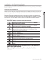
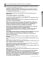
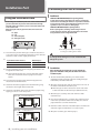
Important safety symbols and precautions:
WARNING
CAUTION
CAUTION
Hazards or unsafe practices that may result in severe
personal injury or death.
Hazards or unsafe practices that may result in minor
personal injury or property damage.
To reduce the risk of fire, explosion, electric shock, or
personal injury when using your air conditioner, follow
these basic safety precautions:
Do NOT attempt.
Do NOT disassemble.
Do NOT touch.
Follow directions carefully.
Unplug the power plug from the wall socket.
Make sure the machine is grounded to prevent electric
shock.
Call the contact center for help.
Note.
These warning signs are here to prevent injury to you and others.
Please follow them carefully.
After reading this section, keep it in a safe place for future
reference.
safety information _03
ENGLISH
Before using your new air conditioner, please read this manual thoroughly to ensure that
you know how to safely and efficiently operate the extensive features and functions of
your new appliance.
safety information
WARNING
SEVERE WARNING SIGNS
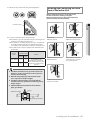
Do not place the air conditioner near hazardous substances or
equipment that releases free flames to avoid fire, explosions or injuries.
• Potential risk of fire hazard or explosion.
Do not install the outdoor unit at an unstable place or elevated surface
where there is potential risk of falling.
• If the outdoor unit falls, it may cause personal injury or loss of property.
Failure or damage may occur if any changes or modification that is not
stated in the installation manual was performed. In this case, user will
be responsible for the repair expenses.
Install the air conditioner away from direct exposure to sunlight,
heating apparatus, and humid places.
• Hang curtains on windows to boost cooling efficiency and to avoid the
risk of electric shock.
Do not cut the power plug and connect to a different power cable.
Do not yank the power cable and touch the power plug with hands.
• Potential risk of fire or electric shock.
Never use a damaged or dusted power plug, power cable, or loosened
power receptacle.
• Potential risk of fire or electric shock.
Install an exclusive circuit breaker and short-circuit breaker for the air
conditioner.
• Potential risk of electric shock or fire.
Do not insert anything such as fingers or branches into the air
conditioner vents while the air conditioner is running.
• Keep the children away from the air conditioner to prevent them from
putting their finger on the air conditioner. Potential risk of personal injury.
Ensure no water gets into the air conditioner.
• Potential risk or electric shock.
• If the water gets into the air conditioner, stop and unplug the power
source immediately.
Turn off the air conditioner using the provided remote control or control
accessory (if provided). Do not unplug to turn off the unit (unless there
is an immediate danger).
Do not run the air conditioner for an extended period of time in a room
with the door closed or with babies, elderly or disabled people.
• Open the door or windows to ventilate your room at least once an hour to
prevent oxygen shortage.
The air conditioner is composed of moving parts. Keep children away
from the unit to avoid physical injury.
04_ safety information
Make sure that children take precautions against access to the air
conditioner and they do not play with the unit.
Do not clean the interior of air conditioner on your own.
• You may damage the parts which can cause electric shock or fire
• Consult contact center for cleaning the interior of the air conditioner.
Consult the place of purchase or contact to install,reinstall or
disassemble the aire conditioner.
• Improper installation carries a risk of unit malfunction, water leakage, electric
shock or fire.
• If installing in specialty areas, such as a factory complex or saline coastal
area, consult the place of purchase or contact center for specific installation
details.
• The units must be installed according to distances declared, in order to
permit accessibility from each side, either to guarantee correct operation of
maintenance or repairing products. The unit’s parts must be reachable and
removable completely under safety condition (for people or things).
Consult a dealer regarding the appropriate measures to prevent the
allowable concentration from being exceeded.
• If the refrigerant leaks, and cause the concentration limit to be exceeded,
hazards due to lack of oxygen in the room may result.
If the indoor unit gets wet, turn the power off immediately and call your
nearest contact center.
• Potential risk of fire or electric shock.
Always make sure that the power supply is compliant with current safety
standards. Always install the air conditioner in compliance with current
local safety standards.
Verify that the voltage and frequency of the power supply comply with
the specifications and that the installed power is sufficient to ensure
the operation of any other domestic appliance connected to the same
electric lines.
Use a rated circuit breaker only.
• Never use steel wires or copper wires as a circuit breaker. It may cause fire
or unit malfunctions.
Do not put undue stress or place heavy object on the power cable.
Do not bend the power cable excessively.
• Potential risk of fire or electric shock.
To protect the product from water and possible shock, you should keep
the power cable and the connection cord of the indoor and outdoor units
in the protection tube.
When opening or closing the front panel, use a stable stool and watch
your steps carefully.
Disconnect the air conditioner from power supply before it is repaired or
disassembled.
Clean the air conditioner after the inner fan stops operating.
• Potential risk of injury or electric shock.
safety information _05
ENGLISH
Do not Connect the air conditioner with heating apparatus or attempt to
disassemble,remodel or repair it yourself.
• Potential risk of malfunction, electric shock or fire. If repairs are needed,
consult the contact center.
safety information
WARNING
SEVERE WARNING SIGNS (CONT’D)
Use a receptacle that has a ground terminal. The receptacle must be
used exclusively for the air conditioner.
• Improper electrical grounding may cause electric shock or fire.
Be sure to ground the unit. Do not connect the ground wire to gas or
water pipes, lighting rods, or telephone grounding lines.
• If the unit is not properly grounded, electric shock may result.
If you smell burning plastic, hear strange sounds, or see smoke coming
from the unit, unplug the air conditioner immediately and call a contact
center.
• Potential risk of fire or electric shock.
CAUTION
CAUTION SIGNS
Do not block or place items in front of the air conditioner. Do not step,
hang onto, or place heavy items on the air conditioner.
• Potential risk of personal injury.
If failure or damage occurs on the conditions of improper use not
followed by the installation manual, there will be an extra labor charge
for installing and construction.
• Potential risk of malfunction, electric shock or fire if repairs or installations
are attempted by a non-qualified service technician.
Do not spray flammable gases such as insecticide near the air
conditioner.
• Potential risk of electric shock, fire or unit malfunction.
Do not open the front grille during operation.
• Potential risk of electric shock or unit malfunction.
Cool air should not flow directly towards people, pets, and plants.
• It is harmful to your health, pets, and plants.
Do not drink drain water coming out of the air conditioner.
• Potential risk of health hazard.
Do not allow children to climb on the air conditioner.
Do not use the air conditioner as a cooling precision instrument for
food, pets, plants, cosmetics or machinery.
Do not pull or give excessive shock to the air conditioner.
• Potential risk of fire, or unit malfunction and there are risk of personal
injury because unit may fall down.
Do not spray water directly on the air conditioner or use benzene,
thinner or alcohol to clean the surface of the unit.
• Potential risk of electric shock or fire.
• Potential risk of damage to the air conditioner.
Do not place any objects, especially containers with liquid.
06_ safety information
Do not touch the pipe connected to the air conditioner.
safety information _07
ENGLISH
Install the indoor unit away from lighting apparatus using the ballast.
• If you use the wireless remote control, reception error may occur due to
the ballast of the lighting apparatus.
Install the outdoor unit where operating noise and vibration will not
disturb your neighbor and in a well-ventilated area with no obstacle.
• Potential risk of malfunction.
• Operating noise may disturb your neighbor.
Make sure that there are no obstacles or covers that block the air
conditioner.
Allow sufficient space for air circulation.
• Insufficient ventilation may result in poor performance.
If the power cable is damaged, the manufacturer or a qualified service
technician must replace it.
If a power outage occurs while the air conditioner is working, turn off
the power source immediately.
Max current is measured according to IEC standard for safety and
current is measured according to ISO standard for energy efficiency.
Check for damage on delivery. If damaged, do not install the air
conditioner and call the place of purchase immediately.
Keep indoor temperatures stable and not extremely cold, especially
where there are children, elderly or disabled people.
The packaging material and used batteries of the remote controller
(optional) must be disposed of in accordance with the national
standards.
The refrigerant used in the air conditioner must be treated as chemical
waste. Dispose the refrigerant following national standards.
Have a qualified service technician install the air conditioner and
perform a trial operation.
Firmly connect the drain hose to the air conditioner for proper water
drainage.
Check for damages on the outdoor unit installation pad at least once a
year.
• Potential risk of personal injury or property loss.
When using a wireless remote control, the distance should not be more
than 7 meters from the air conditioner.
If the remote control is not used for a long period of time, remove the
batteries to prevent leakage of electrolyte.
When cleaning the outdoor unit, touch the heat exchanger radiator fins
with extreme care.
• Wearing thick gloves can protect your hands.
Make sure that the condensed water dripping from the drain hose runs
out properly and safely.
The appliance is not intended for use by persons (including children)
with reduced physical, sensory or mental capabilities, or lack of
experience and knowledge, unless they have been given supervision or
instruction concerning use of the appliance by a person responsible for
their safety: Young children should be supervised to ensure that they
do not play with the appliance.
safety information
CAUTION
CAUTION SIGNS (CONT’D)
Inspect the condition, electric connections, pipes and external case of
the air conditioner regularly by a qualified service technician.
Do not open doors and windows in the room being cooled during
operation unless necessary.
Do not block the air conditioner vents. If objects block the air flow, it
may cause unit malfunction or poor performance.
Make sure there are no obstacles under the indoor unit.
• Potential risk of fire or loss of property.
The air conditioner should be used only for the applications for which
it has been designed: the indoor unit is not suitable to be installed in
areas used for laundry.
Our units must be installed in compliance with the spaces indicated
in the installation manual to ensure either accessibility from both
sides or ability to perform routine maintenance and repairs. The units’
components must be accessible and that can be disassembled in
conditions of complete safety either for people or things.
For this reason, where it is not observed as indicated into the
Installation Manual, the cost necessary to reach and repair the unit
(in safety, as required by current regulations in force) with slings,
trucks, scaffolding or any other means of elevation won’t be considered
in-warranty and charged to end user.
For use in Europe : This appliance can be used by children aged from 8
years and above and persons with reduced physical,sensory or mental
capabilities or lack of experience and knowledge if they have been given
supervision or instruction concerning use of the appliance in a safe way and
understand the hazards involved. Children shall not play with the appliance.
Cleaning and user maintenance shall not be made by children without
supervision.
Ensure the off-on and protection switches are properly installed.
Do not use the air conditioner if damaged. If problems occur,
immediately stop operation and disconnect the plug from the power
supply.
If the air conditioner will not be used for an extended period of time
(for example, over several months), unplug the power from the wall.
Call the place of purchase or a contact center if repairs are needed.
• Potential risk of fire or electric shock if disassembly or repairs are
attempted by a non-qualified service technician.
If you smell burning plastic, hear strange sounds, or see smoke coming
from the unit, unplug the air conditioner immediately and call a contact
center.
• Potential risk of fire or electric shock.
08_ safety information
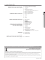
contents
VIEWING YOUR AIR CONDITIONER
10
14
USING ADVANCED FUNCTIONS
16
CLEANING AND MAINTAINING
THE AIR CONDITIONER
19
APPENDIX
24
26
INSTALLING YOUR AIR CONDITIONER
14Selecting operation mode
14Auto
14Cool
14Dry
14Fan
14Heat
16 Turbo operation
16 Air swing
17
operation
18 Setting the On/Off timer
19 Cleaning the exterior
19 Cleaning the filter
19
Air filter
20
Bio filter
21 Replacing the filter
21
Deodorizing filter
22 Maintaining your air conditioner
22
Periodical checks
23Internal protections via the unit control system
24Troubleshooting
25 Operation ranges
26Installation part
This product has been determined to be in compliance with the Low Voltage Directive (2006/95/EC), the Electromagnetic
Compatibility Directive (2004/108/EC) and the Machinery Directive (2006/42/EC) of the European Union.
Correct Disposal of This Product
(Waste Electrical & Electronic Equipment)
(Applicable in countries with separate collection systems)
This marking on the product, accessories or literature indicates that the product and its electronic accessories (e.g. charger, headset, USB cable) should not be
disposed of with other household waste at the end of their working life. To prevent possible harm to the environment or human health from uncontrolled waste
disposal, please separate these items from other types of waste and recycle them responsibly to promote the sustainable reuse of material resources.
Household users should contact either the retailer where they purchased this product, or their local government office, for details of where and how they can
take these items for environmentally safe recycling.
Business users should contact their supplier and check the terms and conditions of the purchase contract. This product and its electronic accessories should
not be mixed with other commercial wastes for disposal.
contents _09
ENGLISH
OPERATING BASIC FUNCTION
10Checking the indoor unit and display
10Main parts
10Display
11Removing the front panel
11Power button and Room temperature sensor
12Remote controller buttons
13Remote controller indicators
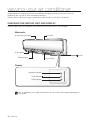
viewing your air conditioner
Congratulations on the purchase of the air conditioner. We hope you enjoy the features of your air
conditioner and stay cool or warm with optimal efficiency.
Please read the user manual to get started and to make the best use of the air conditioner.
CHECKING THE INDOOR UNIT AND DISPLAY
Carefully unpack your air conditioner, and check the unit to make sure it is not damaged.
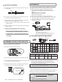
Main parts
Air filter(under the panel)
Air intake
Air flow blade
Power
Blade pin lever
button
Air flow blade
Display
Operation indicator
Timer indicator
Turbo indicator
Your air conditioner may slightly look different from illustration shown above depending on
your model.
10_ viewing
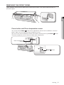
REMOVING THE FRONT PANEL
Tightly grab both side of the front panel and lift up the panel to open. Then slide the panel towards to
remove the panel.
ENGLISH
Power button and Room temperature sensor
You may locate the Power
button on the right bottom side of the air conditioner. If the front
panel is open, you can check the room temperature sensor.
You can turn on the air conditioner without the remote control by pressing the Power
button.
The room temperature sensor measures indoor room temperature.
Room temperature
sensor
Power
button
viewing _11
viewing your air conditioner
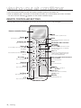
• Point the remote controller towards the remote controller receiver of the indoor unit.
• When you properly press the button on the remote controller, you will hear beep sound from the indoor
unit and a transmit indicator( ) appears on the remote controller display.
REMOTE CONTROLLER BUTTONS
Carefully unpack your air conditioner, and check the unit to make sure it is not damaged.
Remote controller display
Mode
Select one of the 5 operation modes.
Turn the air conditioner on/off.
S-Plasma ion
Has no this function
Turbo
Cool or heat your room quickly and
powerfully.
Air swing
Has no this function
Beep off
Has no this function
Reduce noise generated from an indoor unit
during operation.
This button does not have
a function.
Air swing
Activate/Deactivate air flow blade movement
automatically up and down. (not applicable
to Duct type model)
Fan
Temp +-
Increase/Decrease the temperature
by 1˚C.
Quiet
Power
Adjust amount of air flowing through the air
conditioner with the 4 different fan speeds
such as Auto/Low/Medium/High.
Filter reset (Hold down this button
for 3 seconds.)
Has no this function
Blade
Has no this function
Room
Has no this function
Set the
mode on.
Set/Cancel
On Timer
Set the On Timer on.
nd
2 F
Has no this function
12_ viewing
Set or Cancel the on/off timer,
mode.
Off Timer
Set the Off Timer on.
REMOTE CONTROLLER INDICATORS
Operation mode
indicator
Heat mode* is applicable .
Transmission indicator
2ndF indicator
Low battery indicator
Set temperature & On/
Off set time indicator
Air swing indicator
ENGLISH
Fan speed indicator
On/Off timer indicator
Auto (Turbo)
Low
Medium
High
Room & Blade selection
indicator
Battery changing time
When the battery is exhausted, ( ) will be displayed in the remote controller display. When the icon
appears, change the batteries. The remote controller requires two 1.5V AAA type batteries.
Storing the remote controller
When you do not use the remote controller for long time, remove the batteries from the remote
controller and store it.
Inserting the batteries
1. Push the lever as arrow
2. Insert two AAA batteries.
indicates on the rear side of the Check and match the “+” and “-”
remote controller and pull up.
signs accordingly. Make sure you
have inserted the batteries in
correct position.
CAUTION
NOTE
3. Close the cover by place it back to its
original position.
You should hear click sound when the cover is
locked properly.
• Make sure that water is not allowed to enter the remote controller.
•There is a possibility that the air conditioner will not operate by remote controller near
strong light such as a fluorescent lamp or neon sign. In this case, use the remote
controller in front of the remote controller receiver of the indoor unit.
• If other electrical products are operated by the remote controller, call your nearest
service center.
• To silence the beep sound, press the Beep off button. When you press the Beep
off button again, the beep sound will ring again.
Correct Disposal of Batteries in This product
(Applicable in countries with separate collection systems)
This marking on the battery, manual or packaging indicates that the batteries in this product should not be disposed of with other household waste at the end of
their working life. Where marked, the chemical symbols Hg, Cd or Pb indicate that the battery contains mercury, cadmium or lead above the reference levels in EC
Directive 2006/66. If batteries are not properly disposed of, these substances can cause harm to human health or the environment.
To protect natural resources and to promote material reuse, please separate batteries from other types of waste and recycle them through your local, free battery
return system.
viewing _13
Operating basic function
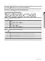
SELECTING OPERATION MODE
Basic operation is an operation mode that can be selected by pressing the Mode button.
Auto
In Auto mode, the air conditioner will automatically set the temperature and fan speed to maintain your fresh
environment.
• When the indoor temperature is too high, the powerful cool breeze is generated and when the indoor
becomes cool enough, the soft breeze is generated.
Cool
Cool mode is frequently used and you can freely control the temperature, fan speed, and air flow direction
in cool mode.
• When you select heat mode while the cool mode is on, the cool mode is canceled.
Dry
The air conditioner in Dry mode acts like a dehumidifier by removing moisture from the indoor air.
Fan
In Fan mode, you can ventilate your room and fan operation will help provide your fresh environment.
Heat
In heat mode, you can warm your room even in the fall and winter
• The fan may not commence immediately to avoid generating a cold breeze.
• Defrost Indicator ( )
- T he defrost indicator will be on when the frost is being removed during the heat operation and when the
defrost function is completed, the defrost indicator will be off.
• If you stop operating the air conditioner after heating operation, the fan will continue for some time to
cool the unit.
• If you select cool mode during the heat mode, the heat mode is canceled.
14_ operating
Press the
button to turn on the air conditioner.
Press the
button to set the operating mode.
• Each time you press the Mode button, the mode will change in order of Auto, Cool, Dry, Fan and Heat.
Press the
button to set the desired fan speed.
Auto
(Auto)
Cool
(Auto),
Dry
(Auto)
Fan
Heat
Press the
ENGLISH
• Heat mode operates only with MR-DH00 model.
(Low),
(Auto),
(Low),
(Med),
(Low),
(Med),
(High)
(High)
(Med),
(High)
button to adjust the desired temperature.
Auto
You can adjust the desired temperature by 1°C(1°F) within the range of 18°C~30°C(65°F~86°F).
Cool
You can adjust the desired temperature by 1°C(1°F) within the range of 18°C~30°C(65°F~86°F).
Dry
You can adjust the desired temperature by 1°C(1°F) within the range of 18°C~30°C(65°F~86°F).
Fan
Temperature adjustment is not possible.
Heat
You can adjust the desired temperature by 1°C(1°F) within the range of 16°C~30°C(61°F~86°F).
operating _15
Using advanced function
Turbo operation
Turbo function will be helpful to cool or heat your room quickly and effectively.
Press the
button on the remote controller in the Cool/Heat mode.
Turbo indicator appears( ) on the remote controller display and the air conditioner operates in
Turbo function for 30 minutes.
If you press the Turbo button again, the Turbo operation is canceled.
• Turbo function is only available in the Cool/Heat mode.
NOTE
• If you select the Turbo operation during the Quiet operation, the Quiet
operation is canceled.
• You can adjust the air flow direction Up/Down or Left/Right.
• You cannot adjust the set temperature and fan speed.
Air swing
This function allows you to shift the air flow direction up and down or left and right.
Press
or
conditioner is on.
button to move the air flow direction up and down or left and right while the air
16_ operating
When the blade reaches the desired position, press the or
button one more
time to set the air flow direction. The up/down and left/right tilting of the blade will
stop.
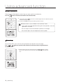
good’ sleep operation
For a comfortable sleep, the air conditioner will operate in Fall asleep Sound sleep Wake up from
good’ sleep mode.
When the air conditioner is on and in cool mode.
1. Press the
button on the remote controller to select the good’ sleep operation.
indicator appears and off timer indicator starts blinking on the remote controller display.
button repeatedly to set off time
You can set the time in half hourly units from 30minute ~ 3hours and hourly units from 3hour ~
12hours.
The operation hour can be set to minimum 30minutes and maximum 12hours.
Default operation hour is set to 8hours.
3. Press the Set/Cancel button to active it.
Off timer indicator stops blinking and set time will be displayed.
If you don’t press Set/Cancel button to start the good’ sleep operation within 10 seconds, the
operation is canceled so you should check the Off indicator on the remote controller display.
Cancel
Press the Set/Cancel button once again.
You can set the desired temperature by 1˚C(1˚F) within the range of
18˚C~30˚C(65˚F~86˚F).
Fan speed will be adjusted automatically according to the
Air flow direction will be adjusted automatically according to the
Temperature and fan speed changes in
mode.
mode.
mode
1. Fall asleep mode : P
rovides you with comfortable environment for a good sleep by rapid cooling and hypnagogue expedition breeze.
2. Sound sleep mode : The sound sleep mode adjust temperature and air flow in wave to maintain healthy skin temperature while it
aids deep sleep. According to the change of good’ sleep operation hours, the sound sleep hour can be longer or shorter.
3. Wake up from
mode : Provides you with the air flow that adjusts your body temperature to wake you up in a fresh status.
NOTE
• The recommended set temperature is 25°C~27°C(77°F~81°F) and 26°C(79°F) is the most ideal
temperature.
If the set temperature is too low, you may feel cold or dry and catch a cold.
• You may not have such a restful sleep if the
is set to 8-hour-operation.
is set too short or long because the default
• If the good’ sleep mode is set less than 4hours, the operation will stop after the set hours. If the
mode is set over 5 hours, it will run as Wake up stage from the last one hour before it
stops automatically.
• If you press Turbo, Mode, Quiet button during the good’ sleep operation, the
operation is canceled and the selected operation starts.
• Only the latest setting timer will be applied between the On Timer/Off Timer and
timer functions.
off
• You can set the S-Plasma ion function during the good’ sleep operation.
operating _17
ENGLISH
2. Press the
Using advanced function
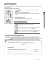
Setting the On/Off timer
You can set the air conditioner to turn on/off automatically at desired time.
Setting On timer while the air conditioner is off / Off timer while the air conditioner is on.
Setting On timer
1.Press On timer or Off timer button.
(On) / (Off) timer indicator will blink on the remote controller display.
2.Press On timer or Off timer button repeatedly to set the time.
You can set the time in half hourly units from 30minute ~ 3hours and hourly units from 3hour ~
24hours.
The set hour is set to minimum 30minutes and maximum 24hours.
3.Press Set/Cancel button to activate it.
(On) / (Off) indicators will stop blinking and the set time will be displayed.
If you don’t press Set/Cancel button within 10 seconds after selecting the on timer or off timer button,
the air conditioner will return to the previous status, so you should check the (On) or (Off) indicator on
the remote controller display.
Cancel
Press the Set/Cancel button once again.
Additional options available in On timer mode
You can select from (Auto) (Cool) (Dry) (Fan) (Heat).
(Heat mode is applicable to MR-DH00/DH00U model only.)
Setting Off timer
You can adjust the temperature in Auto/Cool/Dry/Heat mode
However, you cannot adjust the temperature in fan mode.
(Heat mode is applicable to MR-DH00/DH00U model only.)
NOTE
• Only the latest setting timer will be applied between the On Timer/Off
Timer and
off timer functions.
• About 10 seconds after setting the On timer, only the set time will be
displayed on the remote controller.
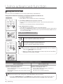
Setting On timer and Off timer simultaneously
If the air conditioner is On
Preset time on On timer is shorter than Off timer
Ex) On timer : 3 hours, Off timer 5 hours
- The air conditioner will turn on after 3 hours from the moment
you have set the timer.
Your air conditioner will remain on for 2 hours and then turn off
automatically.
If the air conditioner is Off
Preset time on On timer is longer than Off timer
Ex) On timer : 3 hours, Off timer : 1 hour
- The air conditioner will be turned off after 1 hour from the
moment you have set the timer.
After 2 hours, your air conditioner will turn on.
• On timer and Off timer setting time should be different from each other.
NOTE
• If you press Set/Cancel button or Power button while the both on timer and off timer are set
simultaneously, the functions of both on timer and off timer are canceled at the same time.
18_ operating
cleaning and maintaining the
air conditioner
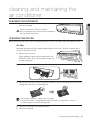
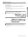
CLEANING THE EXTERIOR
ENGLISH
1. Wipe the surface of the unit with a slightly wet or dry
cloth when needed.
Do not use Benzene, Thinner or CloroxTM.
CAUTION They may damage the surface of the air conditioner
and can create a risk of fire.
CLEANING THE FILTER
When cleaning the filter, make sure to unplug the power from the unit. No special tools are needed to clean it.
Air filter
Washable foam based air filter captures large particles from the air. The filter is cleaned with a
vacuum or by hand washing.
1. Remove the front panel.
Tightly grab both side of the front panel and lift up
the panel to open. Then slide the panel towards you
to remove the panel.
2. Grab the handle and lift it up. Then, pull the Air filter towards you.
3. Clean the Air filter with a vacuum cleaner or soft brush. If dust is too heavy, then rinse it with
running water and dry it in a ventilated area.
• For the best conditions, repeat every two weeks.
• If the Air filter dries in a confined(or humid) area, odors may generate. If it occurs,
re-clean and dry it in a well-ventilated area.
4. Insert the Air filter back in its original position.
5. Close the front panel.
cleaning and maintaining _19
cleaning and maintaining the
air conditioner
Bio filter
Washable foam based Bio filter leads to reduction in allergens that thrive in polluted air. The filter
is cleaned with a vacuum or by hand washing.
1. Remove the front panel.
Tightly grab both side of the front panel and lift up the panel to open. Then slide the panel
towards you to remove the panel.
2. Slide the Bio filter(color in sky-blue) out to remove it from the slot.
•Bio filter can be placed in any 4 slots beneath the air filter.
•Front panel of your air conditioner is actually not detachable.
3. Clean the Bio filter with a vacuum cleaner or soft brush. Then rinse it with running water and
dry it in a ventilated area.
4. Install the Bio filter back in position.
5. Close the front panel.
Clean the Bio filter every 3 months. The cleaning term may differ on usage and
environmental conditions.
20_ cleaning and maintaining
REPLACING THE FILTER
Replacement filter may be purchased from the retail store or ordered from the dealer where you purchased
the unit. If you cannot find one, please call a contact center.
Deodorizing filter
Deodorizing filter absorbs efficiently cigarette smoke, pet odors and other unpleasant smells.
Deodorizing filter cleaning is simple, just remove old filter and install a new one.
Tightly grab both side of the front panel and lift up the panel to open. Then slide the panel
towards you to remove the panel.
2. Slide the Deodorizing filter(color in black) out to remove it from the slot.
•Deodorizing filter can be placed in any 4 slots beneath the air filter.
•Front panel of your air conditioner is actually not detachable.
3. Install the new Deodorizing filter back in position.
4. Close the front panel.
• The replacement timing of the Deodorizing filter differs depending on usage and
environmental conditions.
• Even if Deodorizing and Bio filters are installed in an inverted position, it will not affect its
filtration system.
cleaning and maintaining _21
ENGLISH
1. Remove the front panel.
cleaning and maintaining the
air conditioner
MAINTAINING YOUR AIR CONDITIONER
If the air conditioner will not be used for an extended period of time, dry the air conditioner to maintain it in
best condition.
1. Dry the air conditioner thoroughly by operating in Fan mode for 3 to 4 hours and disconnect
the power plug. There may be internal damage if moisture is left in components.
2. Before using the air conditioner again, dry the inner components of the air conditioner again
by running in Fan mode for 3 to 4 hours. This helps remove odors which may have generated
from dampness.
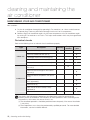
Periodical checks
Refer to the following chart to maintain the air conditioner properly.
Type
Description
Clean the air filter (1)
Indoor unit
Monthly
Every 4
months
Clean the condensate drain pan (2)
Thoroughly clean the heat exchanger (2)
Clean the condensate drain pipe (2)
Replace the remote control batteries (1)
Clean the heat exchanger on the outside of
the unit (2)
Outdoor unit
Once a
year
Clean the heat exchanger on the inside of
the unit (2)
Clean the electric components with jets of
air (2)
Verify that all the electric components are
firmly tightened (2)
Clean the fan (2)
Verify that all the fan assembly is firmly
tightened (2)
Clean the condensate drain pan (2)
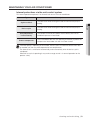
The checks and maintenance operations described are essential to guarantee the
efficiency of the air conditioner. The frequency of these operations varies according to the
characteristics of the area, the amount of dust, etc.
(1) The described operations should be performed more frequently if the area of installation
is very dusty.
(2) These operations must always be performed by qualified personnel. For more detailed
information, see the Installation Manual.
22_ cleaning and maintaining
MAINTAINING YOUR AIR CONDITIONER
Internal protections via the unit control system
This internal protection operates if an internal fault occurs in the air conditioner.
Type
Description
The internal fan will be off to against cold air when the heat pump is
heating.
De-ice cycle
The internal fan will be off to against cold air when the heat pump is
heating.
Anti-protection of
internal battery
Protect compressor
The compressor will be off to protect internal battery when the air
conditioner operates in Cool mode.
The air conditioner does not start operating immediately to protect the
compressor of the outdoor unit after it has been started.
If the heat pump is operating in Heat mode, De-ice cycle is actuated to remove frost from
an outdoor unit that may have deposited at low temperatures.
The internal fan is switched off automatically and restarted only after the de-ice cycle is
completed.
When de-ice cycle is operating,it may make strange sound. It is normal operation for the
product safety.
cleaning and maintaining _23
ENGLISH
Against cold air
appendix
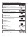
TROUBLESHOOTING
Refer to the following chart if the air conditioner operates abnormally. This may save time and unnecessary
expenses.
PROBLEM
SOLUTION
The air conditioner does
not operate immediately
after it has been
restarted.
• Because of the protective mechanism, the appliance does not start
operating immediately to keep the unit from overloading.
The air conditioner will start in 3 minutes.
The air conditioner does
not work at all.
• Check that the power plug is properly connected. Insert the power plug
into the wall socket correctly.
• Check if the circuit breaker is switched off.
• Check if there is a power failure.
• Check your fuse. Make sure it is not blown out.
The temperature does
not change.
• Check if you selected Fan mode.
Press the Mode button on the remote control to select another mode.
The cool(warm) air does
not come out of the air
conditioner.
• Check if the set temperature is higher(lower) than the current temperature.
Press the Temperature or button on the remote control to change
the set temperature. Press the Temperature or button to increase
or decrease the temperature.
• Check if the air filter is blocked by dirt. Clean the Air filter every two weeks.
• Check if the air conditioner has just been turned on. If so, wait 3 minutes.
The fan speed does not
change.
• Check if you selected Auto or Dry mode.
The air conditioner automatically adjusts the fan speed to Auto in Auto/Dry
mode.
Timer function does not
set.
• Check if you press the Power
& Set/Cancel button on the remote
control after you have set the time.
Odors permeate in the
room during operation.
• Check if the appliance is running in a smoky area or if there is a smell
entering from outside. Operate the air conditioner in Fan mode or open
the windows to air out the room.
The air conditioner
• A bubbling sound may be heard when the refrigerant is circulating through
makes a bubbling sound.
the compressor. Let the air conditioner operate in a selected mode.
Water is dripping from
the air flow blades.
• Check if the air conditioner has been cooling for an extended period of
time with the air flow blades pointed downwards. Condensation may
generate due to the difference in temperature.
Remote control is not
working.
• Check if your batteries are depleted.
• Make sure batteries are correctly installed.
• Make sure nothing is blocking your remote control sensor.
• Check that there are strong lighting apparatus near the air conditioner.
Strong light which comes from fluorescent bulbs or neon signs may
interrupt the electric waves.
If the outdoor temperature is too low when heat mode is operating, special operation will operate and
it may make strange sound.It is normal operation for the product safety.
24_ appendix
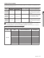
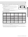
OPERATION RANGES
The table below indicates the temperature and humidity ranges the air conditioner can be operated within.
Refer to the table for efficient use.
MODE
OPERATIONAL TEMPERATURE
INDOOR
OUTDOOR
IF OUT OF CONDITIONS
Condensation may occur on
the indoor unit with risk to have
either water blow off or drops on
the floor.
COOLING
16˚C to 32˚C
-5˚C to 48˚
80% or less
HEATING
27˚C or less
-20˚C to 24˚C
-
Internal protection triggers and
the air conditioner will stop.
-
Condensation may occur on
the indoor unit with risk to have
either water blow off or drops on
the floor.
DRYING
16˚C to 32˚C
-5˚C to 48˚C
The standardized temperature for heating is 7˚C. If the outdoor temperature drops to 0˚C or below,
the heating capacity can be reduced depending on the temperature condition.
If the cooling operation is used at over 32˚C(indoor temperature), it does not cool at its full capacity.
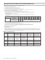
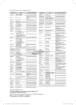
Model specification (Dimension and weight)
Dimension and weight
Type
Indoor unit
Model
Net dimension (WxDxH) (mm)
Net weight (kg)
AM015HNTDEH/EU
825*285*189
8.5
AM022FNTDEH/EU
825*285*189
8.5
AM028FNTDEH/EU
825*285*189
8.5
AM036FNTDEH/EU
825*285*189
8.5
AM045FNLDEH/EU
1065*298*218
12.5
AM071FNTDEH/EU
1065*298*218
12.5
AM015HNQDEH/EU
825*285*189
8.8
AM022FNQDEH/EU
825*285*189
8.8
AM028FNQDEH/EU
825*285*189
8.8
AM036FNQDEH/EU
825*285*189
8.8
AM045FNQDEH/EU
1065*298*218
13
AM056FNQDEH/EU
1065*298*218
13
AM071FNQDEH/EU
1065*298*218
13
appendix _25
ENGLISH
INDOOR HUMIDITY
Installation Part
Performing Leak Test & Insulation
Leak test
Fixing the Installation Plate
Before fixing the installation plate to the wall or window frame,
you must determine the position of the 65mm hole through
which the cable, pipe and hose pass to connect the indoor unit
to the outdoor unit.
When facing the wall, the pipe and cable can be connected
from the:
Right
Left
Underside(right)
Rear(right or left)
LEAK TEST WITH NITROGEN(before opening valves)
In order to detect basic refrigerant leaks, before recreating the
vacuum and recirculating the R410A, it’s responsible of installer
to pressurize the whole system with nitrogen(using a pressure
regulator) at a pressure above 4.1MPa(gauge).
LEAK TEST WITH R410A(after opening valves)
Before opening valves, discharge all the nitrogen into the
system and create vacuum. After opening valves check leaks
using a leak detector for refrigerant R410A.
C
D
g The designs and shape are subject
to change according to the model.
1. Determine the position of the pipe and drain hose hole as
seen in the picture and drill the hole with an inner diameter
of 65mm so that it slants slightly downwards.
2.
If you fix the indoor unit to a...
Follow step(s)...
Wall
3.
Window frame
4 to 6.
3. Fix the installation plate to the wall giving attention to the
weight of the indoor unit.
If you mount the plate to a concrete wall with anchor
bolts, the anchor bolts must not project more than
20mm.
4. Determine the positions of the wooden uprights to be
attached to the window frame.
5. Attach the wooden uprights to the window frame giving
attention to the weight of the indoor unit.
6. Attach the installation plate to the wooden uprights using
tapping screws as seen in the picture.
Discharge all the nitrogen to create a vacuum and
charge the system.
Insulation
After checking for gas leaks in the system, insulate the
pipe, hose and cables. Then place the indoor unit on the
installation plate.
1. To avoid condensation problems, place heat-resistant
polyethylene foam separately around each refrigerant pipe
in the lower part of the indoor unit.
2. Wrap the refrigerant pipe and the drain hose in the rear of
the indoor unit with the absorbent pad.
Wind the pipe and hose three times to the end of the
indoor unit with the absorbent pad. (20mm interval)
3. Wind the pipe, assembly cable and drain hose with
insulation tape.
(Unit : mm) 015/022/028/036
Pipe hole
(Ø65mm)
27
27
4. Place the bundle(the pipe, assembly cable and drain hose)
120
68
in the lower part of the indoor unit carefully so it doesn’t
project from the rear of the indoor unit.
5. Hook the indoor unit to the installation plate and move the
unit to the right and left until it is securely in place.
(Unit : mm)
045/056/071
6. Wrap the rest of the pipe with vinyl tape.
34
34
Pipe hole
(Ø65mm)
140
68
26_ installing your air conditioner
7. Attach the pipe to the wall using clamps(optional).
Installing and Connecting the Drain
Hose of the Indoor Unit
When installing the drain hose for the indoor unit,
check if condensation draining is adequate.
When passing the drain hose through the 65mm hole
drilled in the wall, check the following:
ENGLISH
Installation plate
8. Select the insulation of the refrigerant pipe.
Insulate the gas side and liquid side pipe referring to the
thickness according to the pipe size.
The thickness according to the pipe size is a standard of
the indoor temperature of 27°C and humidity of 80%.
If installing in an unfavorable conditions, use thicker one.
Insulator’s heat-resistance temperature should be more
than 120°C.
Pipe size
(mm)
Minimum thickness
of insulation (mm)
PE foam
EPDM
foam
Ø6.35~Ø15.88
13
10
-
25
19
The hose must
NOT slant upwards.
5cm
less
Remarks
If you install the pipe
underground, at the seaside,
a spa or on the lake, use 1 grade
thicker one according to the
pipe size.
The end of the drain hose must
NOT be placed under water.
Do NOT bend the hose in
different directions.
Keep a clearance of at least
5cm between the end of the
hose and the ground.
Install the insulation not to get wider and use the
adhesives on the connection part of it to prevent
moisture from entering.
Wind the refrigerant pipe with insulation tape
if it is exposed to outside sunlight.
Install the refrigerant pipe respecting that the
insulation does not get thinner on the bent part or
hanger of pipe.
Add the additional insulation if the insulation
plate gets thinner.
Ditch
Do NOT place the end of the
drain hose in a hollow.
Hanger
Additional insulation
a
a×3
Refrigerant pipe insulation
installing your air conditioner _27
Wiring Work
Drain hose installation
1. If necessary, connect the 2 meter extension drain hose to
the drain hose.
Shield
Drain hose
Extension drain hose
2. If you use the extension drain hose, insulate the inside of
the extension drain hose with a shield.
3. Fit the drain hose into 1 of 2 drain hose holes, then fix the
end of the drain hose tightly with a clamp.
Power and communication cable connection
1. Before wiring work, you must turn off all power source.
2. Indoor unit power should be supplied through the
breaker(ELCB or MCCB+ELB) separated by the outdoor
power.
ELCB: Earth Leakage Circuit Breaker
MCCB:Molded Case Circuit Breaker
ELB:Earth Leakage Breaker
3. The power cable should be used only copper wires.
4. Connect the power cable{1(L), 2(N)} among the units within
maximum length and communication cable(F1, F2) each.
5. Connect F3, F4(for communication) when installing the
wired remote Control.
Outdoor
Unit
If you don’t use the other drain hose hole, block it with a
rubber stopper.
Wired Remote
Control
220-240V~
or
4. Pass the drain hose under the refrigerant pipe, keeping the
MCCB+
ELB
ELCB
drain hose tight.
5. Pass the drain hose through the hole in the wall.
Indoor Unit 1 Indoor Unit 2
Check if it slants downwards as seen in the picture.
The hose will be fixed permanently into position
after finishing the installation and the gas leak test.
DO NOT WALL UP THE DRAIN HOSE CONNECTION !
Drain hose connection must be easy accessible and
serviceable.
Indoor Unit 3
h ELCB : Essential Installation
WARNING
Power off before connecting any wires;
Indoor PBA will be damaged while V1,V2,F3,F4 short each other.
h Don’t connect the EEV kit to this model. (AMFNQD)
Selecting compressed ring terminal
Silver solder
Changing Direction of the Drain Hose
You can select the direction of the drain hose, depending on
where you want to install the indoor unit.
1. Detach the rubber cap with the flyer.
B
D
d1
E F L
d2
t
Norminal Norminal
dimensions dimensions Standard
Standard
Standard
Standard
for cable for screw dimension Allowance dimension Allowance dimension Allowance Min. Min. Max. dimension Allowance Min.
(mm)
(mm)
(mm)
(mm)
(mm2)
(mm)
(mm)
(mm)
(mm)
(mm)
1.5
2.5
Screw hole
Screw
Drain hose
2. Detach the drain hose by pulling it and turning to the left.
4
4
4
4
4
6.6
8
6.6
8.5
4
9.5
±0.2
3.4
±0.2
4.2
±0.2
5.6
+0.3
-0.2
+0.3
-0.2
+0.3
-0.2
1.7
±0.2 4.1 6 16
4.3
2.3
±0.2
6 6 17.5
4.3
3.4
±0.2
6 5 20
4.3
+0.2
0.7
0
+0.2
0.8
0
+0.2
0.9
0
Specification of electronic wire
Power supply
MCCB
ELB or ELCB
Power
cable
Earth
cable
Communication
cable
Max : 242V
Min : 198V
XA
X A, 30mmA
0.1 s
2.5mm2
2.5mm2
0.75~1.5mm2
Decide the capacity of ELCB(or MCCB+ELB) by below formula.
3. Insert the drain hose by fixing it into the groove of the drain Power supply cords of parts of appliances for outdoor use shall not
hose and the outlet of the drain pan.
4. Attach the rubber cap with a screwdriver by turning it to
the right until it fixes to the end of the groove.
Drain pan outlet
Rubber cap
be lighter than polychloroprene sheathed flexible cord.
(Code designation IEC:60245 IEC 57 / CENELEC: H05RN-F or
IEC:60245 IEC 66 / CENELEC: H07RN-F )
The capacity of ELCB(or MCCB+ELB) X [A] = 1.25 X 1.1 X ∑Ai
T X : The capacity of ELCB(or MCCB+ELB).
T ∑Ai : Sum of Rating currents of each indoor unit.
T R efer to each installation manual about the rating current of indoor unit.
Decide the power cable specification and maximum length
within 10% power drop among indoor units.
n
Coef×35.6×Lk×ik
k=1
1000×Ak
∑(
28_ installing your air conditioner
)<
10% of input
voltage[V]
T Coef: 1.55
T L k : Distance among each indoor unit[m],
Ak: Power cable specification[mm2], ik : Running current of each unit[A]
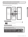
Setting an indoor unit address and installation option
Set the indoor unit address and installation option with remote controller option.
Set the each option separately since you cannot set the ADDRESS setting and indoor unit installation setting option at the same
time. You need to set twice when setting indoor unit address and installation option.
The procedure of option setting
Mode change
High Temp Button
High Fan Button
Low Temp Button
Low Fan Button
Step 1. Entering mode to set option
1. Remove batteries from the remote controller.
2. Insert batteries and enter the option setting mode while pressing High Temp button and Low Temp button.
3.
Check if you have entered the option setting status.
Step 2. The procedure of option setting
After entering the option setting status, select the option as listed below.
Option setting is available from SEG1 to SEG 24
SEG1, SEG7, SEG13, SEG19 are not set as page option.
Set the SEG2~SEG6, SEG8~SEG12 as ON status and SEG14~18, SEG20~24 as OFF status.
SEG1 SEG2 SEG3 SEG4 SEG5 SEG6 SEG7 SEG8 SEG9 SEG10 SEG11 SEG12
0
X
X
X
X
X
1
X
X
X
X
On(SEG1~12)
Off(SEG13~24)
X
SEG13 SEG14 SEG15 SEG16 SEG17 SEG18 SEG19 SEG20 SEG21 SEG22 SEG23 SEG24
2
X
X
X
X
X
3
X
X
X
X
X
installing your air conditioner _29
ENGLISH
Option setting mode
Entering mode for
option setting
Setting an indoor unit address and installation option(Cont.)
Option setting
1. Setting SEG2, SEG3 option
Press Low Fan button(∨) to enter SEG2 value.
Press High Fan button(∧) to enter SEG3 value.
Each time you press the button, … will be selected in rotation.
Status
SEG2
SEG3
SEG4
SEG5
SEG6
SEG8
SEG9
SEG10
SEG11
SEG12
SEG14
SEG15
2. Setting Cool mode
Press Mode button to be changed to Cool mode in the ON status.
3. Setting SEG4, SEG5 option
Press Low Fan button(∨) to enter SEG4 value.
Press High Fan button(∧) to enter SEG5 value.
Each time you press the button, … will be selected in rotation.
4. Setting Dry mode
Press Mode button to be changed to DRY mode in the ON status.
5. Setting SEG6, SEG8 option
Press Low Fan button(∨) to enter SEG6 value.
Press High Fan button(∧) to enter SEG8 value.
Each time you press the button, … will be selected in rotation.
6. Setting Fan mode
Press Mode button to be changed to FAN mode in the ON status.
7. Setting SEG9, SEG10 option
Press Low Fan button(∨) to enter SEG9 value.
Press High Fan button(∧) to enter SEG10 value.
Each time you press the button, … will be selected in rotation.
8. Setting Heat mode
Press Mode button to be changed to HEAT mode in the ON status.
9. Setting SEG11, SEG12 option
Press Low Fan button(∨) to enter SEG11 value.
Press High Fan button(∧) to enter SEG12 value.
Each time you press the button, … will be selected in rotation.
10. Setting Auto mode
Press Mode button to be changed to AUTO mode in the OFF status.
11. Setting SEG14, SEG15 option
Press Low Fan button(∨) to enter SEG14 value.
Press High Fan button(∧) to enter SEG15 value.
Each time you press the button, … will be selected in rotation.
30_ installing your air conditioner
Option setting
Status
12. Setting Cool mode
Press Mode button to be change to Cool mode in the OFF status.
SEG16
SEG17
SEG18
SEG20
SEG21
SEG22
SEG23
SEG24
14. Setting Dry mode
Press Mode button to be change to Dry mode in the OFF status.
15. Setting SEG18, SEG20 option
Press Low Fan button(∨) to enter SEG18 value.
Press High Fan button(∧) to enter SEG20 value.
Each time you press the button, … will be selected in rotation.
16. Setting Fan mode
Press Mode button to be change to Fan mode in the OFF status.
17. Setting SEG21, SEG22 option
Press Low Fan button(∨) to enter SEG21 value.
Press High Fan button(∧) to enter SEG22 value.
Each time you press the button, … will be selected in rotation.
18. Setting Heat mode
Press Mode button to be change to HEAT mode in the OFF status.
19. Setting SEG23, SEG24 mode
Press Low Fan button(∨) to enter SEG23 value.
Press High Fan button(∧) to enter SEG24 value.
Each time you press the button, … will be selected in rotation.
Step 3. Check the option you have set
After setting option, press
button to check whether the option code you input is correct or not.
Step 4. Input option
Press operation button
with the direction of remote control for set.
For the correct option setting, you must input the option twice.
Step 5. Check operation
1. Reset the indoor unit by pressing the RESET button of indoor unit or outdoor unit.
2. Take the batteries out of the remote controller and insert them again and then press the operation button.
installing your air conditioner _31
ENGLISH
13. Setting SEG16, SEG17 option
Press Low Fan button(∨) to enter SEG16 value.
Press High Fan button(∧) to enter SEG17 value.
Each time you press the button, … will be selected in rotation.
Setting an indoor unit address and installation option (Cont.)
Setting an indoor unit address (MAIN/RMC)
1. Check whether power is supplied or not.
- When the indoor unit is not plugged in, there should be additional power
supply in the indoor unit.
Indoor Unit
1(L)
2(N)
2. The panel(display) should be connected to an indoor unit to receive option.
F2
F1
3. Before installing the indoor unit, assign an address to the indoor unit according
to the air conditioning system plan.
4. Assign an indoor unit address by wireless remote controller.
- The initial setting status of indoor unit ADDRESS(MAIN/RMC) is “0A0000-100000-200000-300000”.
Option No. : 0AXXXX-1XXXXX-2XXXXX-3XXXXX
Option
Explanation
SEG1
PAGE
SEG2
MODE
SEG3
SEG4
Setting Main address
100-digit of indoor
unit address
SEG5
SEG6
The unit digit of an
10-digit of indoor unit
indoor unit
Remote
Controller
Display
Indication Details Indication
Indication
and Details
0
Option
SEG7
Explanation
PAGE
Details
Indication
Details
0
No Main
address
1
Main
address
setting
mode
A
SEG8
SEG9
Indication
Details
Indication
Details
0~9
100-digit
0~9
10-digit
SEG10
Setting RMC address
Indication Details
0~9
A unit
digit
SEG11
SEG12
Group channel(*16)
Group address
Remote
Controller
Display
Indication Details
Indication
and Details
_
Indication
Details
0
No RMC
address
1
RMC
address
setting
mode
1
_
Indication
Details
RMC1
0~F
Indication Details
RMC2
0~F
When “A”~”F” is entered to SEG5~6, the indoor unit MAIN ADDRESS is not changed.
If you set the SEG 3 as 0, the indoor unit will maintain the previous MAIN ADDRESS even if you input the option value of SEG5~6.
If you set the SEG 9 as 0, the indoor unit will maintain previous RMC ADDRESS even if you input the option value of SEG11~12.
You cannot set SEG11 and SEG12 as F value at the same time.
32_ installing your air conditioner
Setting an indoor unit installation option (suitable for the condition of each installation location)
1. Check whether power is supplied or not.
- When the indoor unit is not plugged in, there should be additional power
supply in the indoor unit.
Indoor Unit
2. The panel(display) should be connected to an indoor unit to receive option.
3. Set the installation option according to the installation condition of an air F2
F1
conditioner.
- The default setting of an indoor unit installation option is
“020010-100000- 200000-300000”.
- Individual control of a remote controller(SEG20) is the function that controls an
indoor unit individually when there is more than one indoor unit.
4. Set the indoor unit option by wireless remote controller.
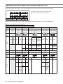
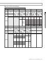
02 series installation option
SEG1
SEG2
SEG3
SEG5
SEG6
Central control
FAN RPM
compensation
SEG9
SEG4
External room
temperature sensor
/ Minimizing fan
operation when
thermostat is off
SEG10
0
2
-
SEG7
SEG8
SEG11
SEG12
1
Drain pump
Hot water heater
-
EEV Step when
heating stops
-
SEG13
SEG14
SEG16
SEG17
SEG18
2
External control
S-Plasma ion
Buzzer
Number of hours
using filter
SEG19
SEG20
SEG15
External control output
/ External heater On or
Off signal
SEG21
SEG22
SEG23
SEG24
EEV Step of
stopped unit during
oil return/defrost
mode
Motion detect sensor
-
3
Heating setting
Individual control of a
compensation /
remote controller
Removing condensated
water in heating mode
1WAY/2WAY/4WAY MODEL : Drain pump(SEG8) will be set to ‘USE + 3minute delay’ even if the drain pump is set to 0.
1 WAY/2WAY/4WAY,DUCT MODEL : Number of hours using filter(SEG18) will be set to ‘1000hour’ even if the SEG18 is set to
except for 2 or 6.
When setting the option other than above SEG values, the option will be set as “0”.
SEG5 central control option is basically set as 1 (Use), so you don’t need to set the central control option additionally.
However, if the central control is not connected but it doesn’t indicate an error message, you need to set the central control
option as 0 (Disuse) to exclude the indoor unit from the central control.
installing your air conditioner _33
ENGLISH
1(L)
2(N)
Setting an indoor unit address and installation option (Cont.)
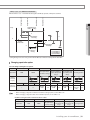
The output of hot water heater in SEG9 is generated from the hot coil part of the terminal board in duct models.
F1
F2
COM1
V1
(+)
F3
V2
(-)
* T he output of hot coil terminal is AC 220 V / 230 V
(The same as Indoor Unit’s input Power)
1(L) 2(N) 1
F4
COM2
L
2
N
OUTDOOR
Remote
AC
DC 12 V Wire
Controller POWER
COMMUNICATION
HOT
COIL
The external output of SEG15 is generated by MIM-B14 connection. (Refer to the manual of MIM-B14.)
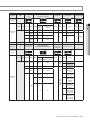
02 series installation option(Detailed)
Option No. : 02XXXX-1XXXXX-2XXXXX-3XXXXX
Option
Explanation
SEG1
SEG2
PAGE
SEG3
SEG4
Use of external room temperature sensor /
Use of robot cleaning Minimizing fan operation when thermostat
is off
MODE
SEG5
SEG6
Use of central control
FAN RPM compensation
Remote
Controller
Display
Details
Indication Details Indication
Details
Indication Details
Indication
and Details
0
0
Option
Explanation
Use of
Minimizing fan
Indication External room
Indication
operation when
temperature
thermostat is off
sensor
Disuse
1
Use
2
SEG7
PAGE
0
SEG8
SEG9
Use of drain pump
Use of hot water
heater
Disuse
Details
Disuse
1
Use
Disuse
2
3
Disuse
Use (*1)
Use (*1)
Use
SEG10
0
Disuse
1
Use
SEG11
EEV Step when heating
stops
Indication
Details
0
Disuse
1
RPM
compensation
2
High ceiling
KIT
SEG12
Remote
Controller
Display
Indication Details Indication
Indication
and Details
Details
Indication Details
Indication
Details
Indication
Details
Default
0
Disuse
0
Disuse
0
1
Use
1
Use (*2)
1
Stopped
Unit’s Noise
Decreasing
Setting
2
--
2
When an
indoor unit
stops, drain
pump will
operate for
3min
2~B
Running
Unit’s Noise
Decreasing
Setting
*3
( )
1
3
34_ installing your air conditioner
Use (*2)
value
Indication
Details
Option
SEG13
Explanation
PAGE
SEG14
Use of external
control
SEG15
Setting the output of external control /
External heater On/Off signal
SEG16
SEG17
SEG18
S-Plasma ion
Buzzer control
Hours of filter usage
Remote Controller
Display
Explanation
PAGE
Heating setting compensation /
Removing condensated water in heating mode
Individual control of a
remote controller
Indication Details Indication
0
1
Disuse
Details
Indication
Details
0
Use buzzer
2
1000 Hour
1
Disuse buzzer
6
2000 Hour
Use
SEG22
EEV Step of stopped
unit during oil return/
defrost mode
SEG23
SEG24
Motion detect sensor
-
Remote Controller
Display
Details
Indication Details Indication Details Indication Heating Setting Removing Condensated Indication Details Indication
Compensation Water in Heating Mode
Default
value
0
0 or 1
channel 1
0
Default (*5)
Disuse
2
channel 2
1
2 °C
Disuse
2
3
channel 3
2
5 °C
Disuse
3
3
Default (*5)
Use (*6)
4
4
2 °C
Use (*6)
Indication and
Details
3
0
1
4
channel 4
5
5 °C
Use (*6)
Oil return
or Noise
decreasing
in defrost
mode
1
5
6
7
8
Details
Disuse
Turn out in 30min.
without motion
Turn out in 60min.
without motion
Turn out in
120min. without
motion
Turn out in
180min. without
motion
Turn out in 30min.
without motion
or *advanced
function
Turn out in 60min.
without motion
or *advanced
function
Turn out in
120min. without
motion or *advanced function
Turn out in
180min. without
motion or *advanced function
installing your air conditioner _35
ENGLISH
Details
Setting the
Indication Details Indication Details Indication output of
External heater On/
external
Off signal
control
0
Disuse
0
Thermo on
Indication and
ON/OFF
Operation
Details
1
1
control
on
OFF
2
2
2
Use (*4)
control
Window
3
ON/OFF
3
Use (*4)
control
Option
SEG19
SEG20
SEG21
Setting an indoor unit address and installation option (Cont.)
*
Advanced function: Controlling cooling/heating current or power saving with motion detect.
(*1) Minimizing fan operation when thermostat is off
- Fan operates for 20 seconds at an interval of 5 minutes in heat mode.
(*2) 1: Fan is turned on continually when the hot water heater is turned on,
3: Fan is turned off when the hot water heater is turned on with cooling only indoor unit
Cooling only indoor unit: To use this option,install the Mode Select switch(MCM-C200) on the outdoor unit and fix it as cool mode.
(*3) It is only for wall-mounted indoor unit with EEV Integrated.
If any design condition meets either of the following below, please set SEG11 to “7”.
a) The total number of wall-mounted indoor units with EEV Integrated in one (modular) system is more than 20.
b) The total number of wall-mounted indoor units with EEV Integrated in one (modular) system is more than “the total of one(modular)
system’s capacity(kW) / 2”
(“the total of one(modular) system’s capacity(BTU/h) / 6800”).
ex) Outdoor capacity 28kW → 28 /2 = 14. The total number of wall-mounted indoor units with EEV Integrated in one (modular) system
is more than 14.
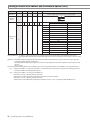
Please refer to the EEV step table below for the system (for heating) at stop.
Indication
Stopped Unit's
EEV step
0
1
2
3
4
5
6
7
8
9
A
B
Wall Mounted
With EEV
80
0
90
100
110
120
130
160
200
250
300
400
Other Indoor Units except for
wall mounted with EEV
Default
0
No Function
(*4) When the following 2 or 3 is used as external heater On/Off signal, the signal for monitoring external contact control will not be output.
2: Fan is turned on continually when the external heater is turned on,
3: Fan is turned off when the external heater is turned on with cooling only indoor unit
Cooling only indoor unit: To use this option,install the Mode Select switch(MCM-C200) on the outdoor unit and fix it as cool mode.
· If Fan is set to off for cooling only indoor unit by setting the SEG9=3 or SEG15=3, you need to use an external sensor or wired remote
controller sensor to detect indoor temperature exactly.
(*5) Default setting value
- 4Way Cassette, Mini 4Way Cassette: 5 °C
- Other indoor units: 2 °C
(*6) This function can be applied to 4 Way Cassette and Mini 4 Way Cassette only. If the air conditioner operates the heating mode immediately after finishing the cooling
mode, the condensated water in the drain pan becomes water vapor by the heat of the indoor unit heat exchanger. Since the water vapor might be condensed on
the indoor unit, which may fall into a living space, use this function to get rid of the water vapor out of the indoor unit by operating the fan (for maximum 20 minutes)
even when the indoor unit is turned off after cooling mode is turned to heating mode .
05 series installation option
SEG1
SEG2
SEG3
SEG4
SEG5
SEG6
(When setting SEG3)
Standard cooling temp.
Offset
SEG11
(When setting SEG3)
Standard for mode change
Heating → Cooling
SEG12
-
-
0
5
Use of Auto Change Over
for HR only in Auto mode
SEG7
SEG8
SEG9
1
(When setting SEG3)
Standard for mode change
Cooling → Heating
(When setting SEG3)
Time required for mode
change
(When setting SEG3)
Standard heating temp.
Offset
SEG10
Compensation option
for Long pipe
or height difference
between indoor units
SEG13
SEG14
SEG15
SEG16
SEG17
SEG18
2
-
-
-
-
Control variables when using
hot water / external heater
SEG19
SEG20
SEG21
SEG22
SEG23
SEG24
3
-
-
-
-
-
36_ installing your air conditioner
05 series installation option(Detailed)
Option No. : 05XXXX-1XXXXX-2XXXXX-3XXXXX
Option
Explanation
SEG1
SEG2
PAGE
SEG3
SEG4
SEG5
SEG6
MODE
Remote
Controller
Display
Indication Details Indication Details Indication
0
Indication
and Details
0
5
1
Option
SEG7
SEG8
Explanation
PAGE
(When setting SEG3)
Standard for
mode change
Cooling → Heating
Details
Indication
Details
Follow
product
option
0
0
0
0
0
1
Use Auto
Change
Over for
HR only
1
2
3
4
5
6
7
0.5
1
1.5
2
2.5
3
3.5
1
2
3
4
5
6
7
0.5
1
1.5
2
2.5
3
3.5
1
2
3
4
5
6
7
1.5
2
2.5
3
3.5
4
4.5
SEG9
SEG10
Indication Details Indication Details
SEG11
SEG12
Compensation option
(When setting SEG3) for
Long pipe or height
Time required
diffference between
for mode change
indoor units
Remote
Controller
Display
Indication Details Indication Details Indication
Indication
and Details
Details
0
1
0
5 min.
1
2
1.5
2
1
2
7 min.
9 min.
3
2.5
3
11 min.
4
5
6
3
3.5
4
4
5
6
13 min.
15 min.
20 min.
7
4.5
7
30 min.
Indication
Details
0
Use default
value
1
1) Height
difference1)
is more
than 30m
or
2) Distance2)
is longer
than 110m
2
1) Height
difference1)
is 15~30m
or
2) Distance2)
is 50~110m
1
installing your air conditioner _37
ENGLISH
setting SEG3)
Use of Auto Change (When setting SEG3) (When setting SEG3) (When
Standard for mode
Over for HR only in Standard heating temp. Standard cooling
change
Auto mode
Offset
temp. Offset
Heating → Cooling
Setting an indoor unit address and installation option (Cont.)
Option
SEG13
SEG14
SEG15
SEG16
SEG17
SEG18(*3)
Explanation
Control variables when using hot water / external heater
Remote
Controller
Display
Indication
Indication and
Details
2
0
1
2
3
4
5
6
7
8
9
A
B
C
D
E
Details
Set temp. for heater On/Off
Delay time for heater On
At the same time as thermo on
No delay
At the same time as thermo on
10 minutes
At the same time as thermo on
20 minutes
1.5 °C
No delay
1.5 °C
10 minutes
1.5 °C
20 minutes
3.0 °C
No delay
3.0 °C
10 minutes
3.0 °C
20 minutes
4.5 °C
No delay
4.5 °C
10 minutes
4.5 °C
20 minutes
6.0 °C
No delay
6.0 °C
10 minutes
6.0 °C
20 minutes
(*1) Height difference : The difference of the height between the corresponding indoor uint and the indoor unit installed at the lowest place.
For example, When the indoor unit is installed 40m higher than the indoor unit installed at the lowest place, select the option
"1".
(*2) Distance : The difference between the pipe length of the indoor unit istalled at farthest place from an outdoor unit and the pipe length of the
corresponding indoor unit from an outdoor unit.
For example, when the farthest pipe length is 100 m and the corresponding indoor unit is 40 m away from an outdoor unit, select the
option "2".
(100 - 40 = 60m)
(*3) Heater operation when the SEG9 of 02 series installation option is set to using hot water heater or when SEG15 is set to using external heater
e.g. 1) Setting 02 series SEG9 =”1” / Setting 05 series SEG18 = “0”: Hot water heater is turned on at the same time as the heating thermostat is
on, and turned off when the heating thermostat is off.
e.g. 2) Setting 02 series SEG15 =”2” / Setting 05 series SEG18 =”A”:
Room temp. ≤ set temp. + f(heating compensation temp.)
- External heater is turned on when the temperature is maintained as 4.5 °C for 10 minutes.
Room temp. > set temp. + f(heating compensation temp.)
- External heater is turned off when the temperature is maintained as 4.5 °C + 1 °C (1 °C is the Hysteresis for On/Off selection.)
38_ installing your air conditioner
SEG 3, 4, 5, 6, 8, 9 additional information
Heating Thermo On
Heating Thermo Off
Cooling Thermo On
ENGLISH
Cooling Thermo Off
When the SEG 3 is set as "1" and follow Auto Change Over for HR only operation, it will operate as follows.
Standard temp. for
Heating → Cooling
Temp.
c
b
Standard temp.
for Cooling
Ts
B
C
D
A
Set temp.
for Auto mode
a
Standard temp.
for Heating
d
Standard temp.
for Cooling →
Heating
A : Set with SEG4(˚C)
B : Set with SEG5(˚C)
C : Set with SEG6(˚C)
D : Set with SEG8(˚C)
Cooling/Heating mode can be changed when Thermo Off status is maintained during the time with SEG9.
Changing a particular option
You can change each digit of set option.
Option
SEG1
Explanation
SEG2
PAGE
MODE
SEG3
SEG4
SEG5
SEG6
The option mode
you want to change
The tens’ digit of an
option SEG you will
change
The unit digit of an
option SEG you will
change
The changed value
Indication
Details
Indication
Details
Indication
Details
Indication
Details
Option
mode
1~6
Tens’ digit
of SEG
0~9
Unit digit of
SEG
0~9
The
changed
value
0~F
Remote
Controller
Display
Indication
Indication
and Details
Note
Details
Indication
0
Details
D
• When changing a digit of an indoor unit address setting option, set the SEG3 as ‘A’.
• When changing a digit of indoor unit installation option, set the SEG3 as ‘2’.
Ex) When setting the ‘buzzer control’ into disuse status.
Option
SEG1
SEG2
Explanation
PAGE
MODE
Indication
0
D
SEG3
SEG4
SEG5
SEG6
The tens’ digit of an The unit digit of an
The option mode
option SEG you will option SEG you will The changed value
you want to change
change
change
2
1
7
1
installing your air conditioner _39
QUESTIONS OR COMMENTS?
COUNTRY
AUSTRIA
CALL
0800 - SAMSUNG (0800 - 7267864)
OR VISIT US ONLINE AT
www.samsung.com/be/support
BELGIUM
02-201-24-18
COUNTRY
CALL
www.samsung.com/at/support
(Ukrainian)
UKRAINE
0-800-502-000
(French)
MOLDOVA
0-800-614-40
www.samsung.com/support
U.A.E
800-SAMSUNG (800 - 726 7864)
(Dutch)
www.samsung.com/ua_ru/support
(Russian)
www.samsung.com/be_fr/support
www.samsung.com/support
BOSNIA
051 331 999
BULGARIA
800 111 31 , Безплатна телефонна линия www.samsung.com/bg/support
OMAN
800-SAMSUNG (800 - 726 7864)
CROATIA
072 726 786
www.samsung.com/hr/support
KUWAIT
183-CALL (183-2255)
CZECH
800 - SAMSUNG (800-726786)
www.samsung.com/cz/support
BAHRAIN
8000-GSAM (8000-4726)
DENMARK
70 70 19 70
www.samsung.com/dk/support
QATAR
800-CALL (800-2255)
FINLAND
030-6227 515
www.samsung.com/fi/support
FRANCE
01 48 63 00 00
www.samsung.com/fr/support
GERMANY
CYPRUS
ITALIA
LUXEMBURG
021 36 11 00
www.samsung.com/n_africa/support
PAKISTAN
0800-Samsung (72678) www.samsung.com/pk/support
(*0,20 €/Anruf aus dem dt. Festnetz, aus dem
TUNISIA
80-1000-12 www.samsung.com/n_africa/support
Mobilfunk max. 0,60 €/Anruf)
[HHP] 0180 6 M SAMSUNG bzw.
www.samsung.com/de/support
JORDAN
(*0,20 €/Anruf aus dem dt. Festnetz, aus dem
IRAN
021-8255
www.samsung.com/iran/support
Mobilfunk max. 0,60 €/Anruf)
MOROCCO
080 100 2255
www.samsung.com/n_africa/support
SAUDI ARABIA
920021230
TURKEY
444 77 11
www.samsung.com/tr/support
ARGENTINE
0800-333-3733
www.samsung.com/ar/support
URUGUAY
000 405 437 33
www.samsung.com/latin/support (Spanish)
PARAGUAY
009 800 542 0001
8009 4000 only from landline, toll free
land line
www.samsung.com/sa/support
www.samsung.com/gr/support
0680SAMSUNG (0680-726-786)
0680PREMIUM (0680-773-648)
800-SAMSUNG(800.7267864)
[HHP] 800.Msamsung (800.67267864)
261 03 710
080 697 267
090 726 786
http://www.samsung.com/hu/support
www.samsung.com/it/support
www.samsung.com/support
www.samsung.com/support
www.samsung.com/si/support
www.samsung.com/no/support
815 56480
[HHP] 0 801-672-678* lub +48 22 607-93-33** www.samsung.com/pl/support
** (koszt połączenia według taryfy operatora)
SLOVAKIA
SPAIN
SWEDEN
808 20 7267
08008 726 78 64 (08008 SAMSUNG )
Apel GRATUIT
011 321 6899
0800 - SAMSUNG(0800-726 786)
0034902172678
[HHP] 0034902167267
0771 726 7864 (SAMSUNG)
BRAZIL
CHILE
BOLIVIA
www.samsung.com/latin_en/support
(English)
0800-124-421 (Demais cidades e regiões)
4004-0000 (Capitais e grandes centros)
800-SAMSUNG(726-7864)
[HHP] 02-24828200
800-10-7260
www.samsung.com/br/support
www.samsung.com/cl/support
www.samsung.com/cl/support
[HHP] 4828210
Bogotá 600 12 72
COLOMBIA
Gratis desde cualquier parte del país 01 8000
www.samsung.com/co/support
112 112 ó desde su celular #SAM(726)
www.samsung.com/pt/support
COSTA RICA
www.samsung.com/ro/support
DOMINICA
www.samsung.com/rs/support
0-800-507-7267
00-800-1-SAMSUNG (726-7864)
1-800-751-2676
1-800-10-72670
www.samsung.com/sk/support
ECUADOR
www.samsung.com/es/support
EL SALVADOR 800-6225
www.samsung.com/se/support
GUATEMALA
www.samsung.com/ch/support
SWITZERLAND 0848 726 78 64 (0800-SAMSUNG)
www.samsung.com/sa_en/support
(English)
0 801-172-678* lub +48 22 607-93-33 **
SERBIA
(English)
18252273
NORWAY
ROMANIA
www.samsung.com/Levant/support
065777444
SYRIA
www.samsung.com/nl/support
PORTUGAL
800-22273
0180 6 67267864*
NETHERLANDS 0900-SAMSUNG (0900-7267864) (€ 0,10/Min)
POLAND
www.samsung.com/eg/support
16580
ALGERIA
MONTENEGRO 020 405 888
SLOVENIA
08000-726786
www.samsung.com/ae_ar/support (Arabic)
0180 6 7267864*
(+30) 210 6897691 from mobile and land line
HUNGARY
EGYPT
www.samsung.com/ae/support (English)
0180 6 SAMSUNG bzw.
80111-SAMSUNG (80111 726 7864) only from
GREECE
OR VISIT US ONLINE AT
www.samsung.com/ua/support
(German)
HONDURAS
www.samsung.com/ch_fr/support
(French)
U.K
0330 SAMSUNG (7267864)
www.samsung.com/uk/support
EIRE
0818 717100
www.samsung.com/ie/support
LITHUANIA
8-800-77777
www.samsung.com/lt/support
LATVIA
8000-7267
www.samsung.com/lv/support
ESTONIA
800-7267
www.samsung.com/ee/support
RUSSIA
8-800-555-55-55
www.samsung.com/ru/support
GEORGIA
0-800-555-555
www.samsung.com/support
ARMENIA
0-800-05-555
www.samsung.com/support
AZERBAIJAN
0-88-555-55-55
www.samsung.com/support
KAZAKHSTAN
8-10-800-500-55-500(GSM: 7799, VIP care 7700)
www.samsung.com/support
UZBEKISTAN
8-10-800-500-55-500
www.samsung.com/support
KYRGYZSTAN
8-10-800-500-55-500
www.samsung.com/kz_ru/support
TADJIKISTAN
8-10-800-500-55-500
www.samsung.com/support
MONGOLIA
'7-495-363-17-00
www.samsung.com/support
BELARUS
810-800-500-55-500
www.samsung.com/support
JAMAICA
NICARAGUA
PANAMA
1-800-SAMSUNG (72-6786)
TOBAGO
www.samsung.com/latin_en/support
(English)
1-800-299-0013
1-800-299-0033
800-27919267
800-2791-9111
1-800-234-7267
www.samsung.com/latin_en/support
1-800-SAMSUNG (726-7864)
(English)
00-1800-5077267
800-7267
www.samsung.com/latin/support (Spanish)
800-0101
www.samsung.com/latin_en/support
PUERTO RICO 1-800-682-3180
TRINIDAD &
www.samsung.com/latin/support (Spanish)
(English)
1-800-SAMSUNG(726-7864)
0-800-777-08
PERU
(Delete) Desde celulares por favor llamar
www.samsung.com/pe/support
al número 336 8686
VENEZUELA
0-800-SAMSUNG (726-7864)
www.samsung.com/ve/support
AUSTRALIA
1300 362 603
www.samsung.com/au/support
1-800-10-7267864 [PLDT]
PHILIPPINES
1-800-8-7267864 [Globe landline and Mobile]
www.samsung.com/ph/support
02-4222111 [Other landline]
SINGAPORE
1800-SAMSUNG(726-7864)
SAMSUNG ELECTRONICS CO.,LTD.
No.501 Suhong East Road,Suzhou Industrial Park,Jiangsu Province,P.R.China
Samsung Electronics (UK) Ltd, Euro QA Lab.
Blackbushe Business Park. Saxony Way, Yateley, Hampshire. GU46 6GG United Kingdom
www.samsung.com/sg/support
"AEEE Yönetmeliğine Uygundur"
"This product is RoHS compliant"
Wall Mounted Type Series
AMTTTFNTDTTT
AMTTTFNQDTTT
Air Conditioner
user manual
imagine the possibilities
Thank you for purchasing this Samsung product.
DB68-03633A-08