1
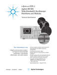
Agilent N1021B
Differential TDR Probe
User’s Guide
2
N1021B
User’s Guide
Agilent N1021B—At a Glance 2
Proper Handling Techniques
5
Adjusting the Probe Tip Separation 7
Attaching to a Positioner
8
Calibrating the Probe 9
Performing an Operation Verification 11
Probing a Differential Trace’s Length
Midpoint 15
Probe Characteristics
16
Returning the Probe for Service 17
Safety Symbols
18
Agilent N1021B—At a Glance
The N1021B facilitates differential time domain
reflectometry measurements in situations where RF
connectors are unavailable. It is ideal for use with the
Agilent 54754A TDR plug-in module. Although the
N1021B probe was designed for TDR applications, it
is also suitable as a high bandwidth, passive probe
for non-TDR applications.
2
2
Using the Probe
■ Refer to “Proper Handling Techniques” on page 5
before using the probe for the first time.
■ Refer to “Calibrating the Probe” on page 9 to calibrate the test setup for use with the probe.
CAUTION
Electrostatic discharge (ESD) can damage or destroy
electronic components and the input circuits on plugin modules. Coaxial cables with both ends
unconnected may store electrostatic charges. Before
connecting any coaxial cable to a device or
instrument, momentarily short the center and outer
conductors of the cable. When making connections,
ensure the proper use of a grounded, resistor-isolated
wrist strap.
CAUTION
Before connecting the phase-matched cables, always
discharge any static buildup. Momentarily short the
center and outer conductors of the cable together.
Avoid touching the front-panel input connectors
without first touching the frame of the instrument.
3
3
Supplied Accessories
Table 1 lists the items provided with the probe. The
information on the actual shipping list is more accurate and should supersede the information in this
list. To order the parts listed in the table, search for
“Parts” at www.agilent.com/Find/Parts. There are no
replaceable parts on the probe.
Table 1. Items Supplied With N1021B
Item
4
4
Qty
Part Number
Pair of phase-matched cables
(1m)
1
N1021-60003
SMA 50Ω Load (m)
2
1810-0118
SMA Short (m)
2
0960-0055
SMA Adapter (f-f)
2
1250-1666
Positioner Adapter
1
N1021-60008
M2.5 socket-head screws (6 mm
long)
2
—
M2.5 Allen wrench
1
—
ESD Wrist Strap
1
9300-1367
ESD Wrist Strap Ground Cord
1
9300-0980
Proper Handling Techniques
Use the following techniques to avoid damaging the
probe. The probe tips are not replaceable.
■ Hold the probe perpendicular to the device under
test. Probing angles greater than 15° from perpendicular will likely damage the tips over time.
■ Do not apply side force to the probe tips.
■ Avoid fully compressing the probe-tip springs.
■ Hand tighten the cable connection to the probe. Or,
5
5
use a 5 in-lb (0.56 Nm) torque wrench.
■ Before cleaning the external case parts of the
N1021B, disconnect the probe from all cables. Use
a dry cloth or one slightly dampened with a mild
soap and water solution. Do not attempt to clean
internally.
CAUTION
Applying excessive force when handling the probe can
result in bent or otherwise damaged probe tips. Apply
only enough pressure to ensure a secure connection.
The probe tips are spring loaded. Avoid fully
compressing the probe-tip springs. The probe tips are
not replaceable.
CAUTION
Do not use too much liquid in cleaning the probe.
Water can enter the case.
6
6
Adjusting the Probe Tip Separation
Turn the probe spacing adjustment wheel to change
the spacing between the probe tips. Avoid using
excessive force at the limits of the adjustment range.
7
7
Attaching to a Positioner
The supplied adapter allows you to attach the probe
to the N1020A TDR Probe positioner, as well as many
robotic arms and common industry positioners. Two
M2.5 socket-head screws (6 mm long) and an Allen
wrench are provided to attach the adapter to the
N1021B. The two screw holes on the probe are separated by ¼-inch (6.4 mm) on center. Torque each
screw to 5 in-lb (0.56 Nm). A ¼-inch hole in the
adapter is used to attach the adapter to the positioner.
8
8
Calibrating the Probe
The differential probe tips do not have a ground,
which is required for a calibration. However, due to
the short electrical length of the probe, the frequency-dependent losses of the probe are small compared to those of the cables. Use the following
procedure to calibrate the path to the input of the
probe.
1 On the 86100C, click Help > Contents on the menu
bar. This will open the online help.
2 In the online help, click TDR/TDT Mode > Tools >
Differential Skew > To adjust differential TDR
skew.
3 Follow the steps in the To adjust differential TDR
skew topic to perform the following items:
■
■
■
■
Module calibration
De-skew the two test-setup cable paths
TDR measurement setup
TDR calibration.
Use the N1021B kit’s phase-matched cables for the test
setup cables referred to in the procedure. Do not connect these cables
during the module calibration. The cables must be connected for the
remaining steps in the procedure.
NOTE
NOTE
The test device is the N1021B probe.
When the TDR calibration instructs you to disconnect everything from the module, leave the cables connected to the module; the
cables must be included in the TDR calibration.
NOTE
9
9
4 Connect the probe to the cables and use the
horizontal controls to position the portion of the
response that corresponds to the end of the probe
at the left side of the display.
5 Connect the DUT (Device-Under-Test).
10
10
Performing an Operation Verification
There are no warranted product specifications to
measure product performance against. Use this TDR
measurement to confirm if the probe is operational.
For additional information on TDR measurements,
refer to the 86100C online help.
1 Turn on the 86100C with the TDR module in the
left slot and allow it to warm up for one hour.
2 Press the Default Setup and then TDR/TDT Mode
buttons.
3 Click Measure > Configure Meas and select the
Thresholds tab. Select the 20%, 50%, 80%
Thresholds Definitions setting. Close the dialog
box.
4 Click Calibrate > All Calibrations and select the
Modules tab. Click Calibrate Left (or Right)
Module depending on the position of the TDR
module. Always use high quality terminations for
best results.
5 Connect the N1021B kit’s phase-matched cables to
the TDR module’s inputs. The cables must remain
connected for the remainder of the procedure.
6 On the Setup toolbar, click S-Param Options, if
displayed. Clear the Show Windowed Region
selection and close the dialog box.
7 On the Setup toolbar, click TDR Setup.
8 In the dialog box, select the Differential
stimulus mode. Select the one-port balanced
test device. Clear all the measurements listed in
11
11
Measurement Results.
9 Click De-skew. The Start and Stop waveform
markers will probably be located on the incident
(first) step response as shown here.
10 Increase the horizontal time span to view both
incident and reflected step responses. The
reflected response is from the end of the cables.
11 Position the reflected response near the display’s
left edge, then decrease the horizontal span while
keeping the reflected response displayed. Repeat
until the span is approximately 50 ps/div.
When you move the incident step response off the display’s
left edge, the markers automatically move right to the reflected step
response as shown above.
NOTE
12 In the Measure table, locate the mean delta time
value. Identify the channel having the longest
path. In the Differential TDR Skew dialog box’s
Horizontal Skew setting for the longest channel,
enter half the mean delta time value.
13 Next, adjust the TDR Skew setting to eliminate
skew between the channels. Close the dialog box.
12
12
14 Connect the N1021B probe at the end of the
cables. Click Calibration Wizard. The reference
plane is located at the point where the cables
attach to the probe.
When the TDR calibration instructs you to disconnect everything from the module, disconnect the cables at the probe. Leave the
cables connected to the module. The cables must be included in the
TDR calibration as you are establishing the measurement reference
plan at the end of the cables.
NOTE
15 After the calibration completes, close the
Calibration Wizard.
16 In the TDR/TDT Setup dialog box, enter an
Effective Rise Time of 15 ps. Close the dialog box.
17 Connect the cables to the probe.
18 Adjust the probe spacing wheel to move the two
probe tips together so that they touch creating a
short.
19 Move the response of the probe’s tip to the
screen’s left side. Reduce the horizontal span
while repositioning the response to the left side.
This action ensures that the response remains
displayed. Repeat until the span setting is 50 ps/
div as shown along the display’s bottom edge.
20 Center the response.
21 If you need to adjust the amplitude position and
scale of the response, click the Response button
on the Setup tab.
22 Select the Measure toolbar and click Fall Time.
23 Click Setup > Averaging and enter 16 for the
Number of Averages. Close the dialog box.
13
13
24 Using the following equation, calculate the BW of
the probe. This simplified equation estimates oneway bandwidth, based on the measured fall time
in seconds. This is a conservative estimate for
bandwidth, because it includes neither the fall
time of the calibrated 54754A module nor the
cables.
0.2379 2
BW probe = -------------------------T fall time
For example, the 18.4 ps fall time shown in the following figure results in a 18.3 GHz BW.
If the 86100C has Option 202 Enhanced Impedance and SParameter software installed, you can view the SDD11 results for a
measurement of the two-way bandwidth.
NOTE
14
14
Probing a Differential Trace’s Length
Midpoint
What are the effects of probing a differential trace
midway along the trace’s length? At the probe’s tip,
the TDR pulse splits into two parts traveling in
opposing directions away from the probe. To the
probe, it appears that two impedances are connected
in parallel. The net effect of probing in the middle of
traces are as follows:
■ The transmitted signal is greatly attenuated.
■ The reflected signal, as viewed and measured by
the TDR module, is greatly attenuated.
■ A large discontinuity appears in the line that sends
a reflection back to the source.
15
15
Probe Characteristics
The following are nominal characteristics of the
probe and do not describe warranted performance.
However, performance which is deemed grossly different than the listed characteristics will be covered
by a 1 year warranty
Table 2. Characteristics of TDR Probe
Description
Characteristic
Bandwidth (pitch dependent)
Up to 18 GHz
Nominal Differential Impedance
100 Ohm
Durability
> 7500 touchdowns
with force ≤10N
Probe Tip Spacing (Variable)
0 mm – 2.54 mm
16
16
Returning the Probe for Service
For technical assistance, contact your local Agilent
Call Center. Please notify the service office before
returning your probe for service. Any special
arrangements for the probe can be discussed at this
time. This will help the Agilent service office repair
and return your instrument as quickly as possible.
■ In the Americas, call 1 (800) 829-4444
■ Visit http://www.agilent.com/find/assist
If the probe is still under warranty or is covered by
an Agilent maintenance contract, it will be repaired
under the terms of the warranty or contract. If the
probe is no longer under warranty or is not covered
by an Agilent maintenance plan, Agilent will notify
you of the cost of the repair after examining the unit.
When a probe is returned to an Agilent service office
for servicing, it must be adequately packaged and
have a complete description of the failure symptoms
attached. When describing the failure, please be as
specific as possible about the nature of the problem.
Perform the procedure located in “Performing an
Operation Verification” on page 11. Upon completion
of the procedure, print out an image of the probe’s
TDR response and include the print out with the
returned probe. (On the 86100C, click File > Print.) If
the phase-matched cables supplied with the probe
are suspect, return the cables with the probe. Do not
return the entire kit including accessories.
17
17
Safety Symbols
CAUTION
The caution sign denotes a hazard. It calls attention to
a procedure which, if not correctly performed or
adhered to, could result in damage to or destruction of
the product. Do not proceed beyond a caution sign
until the indicated conditions are fully understood and
met.
W A R N I N G The warning sign denotes a hazard. It calls
attention to a procedure which, if not correctly
performed or adhered to, could result in injury
or loss of life. Do not proceed beyond a
warning sign until the indicated conditions are
fully understood and met.
18
18
Notice.
The information contained in this document is subject to change without
notice. Companies, names, and data used in examples herein are fictitious
unless otherwise noted. Agilent Technologies makes no warranty of any kind
with regard to this material, including but not limited to, the implied warranties of merchantability and fitness for a particular purpose. Agilent Technologies shall not be liable for errors contained herein or for incidental or
consequential damages in connection with the furnishing, performance, or
use of this material.
Restricted Rights Legend.
Use, duplication, or disclosure by the U.S. Government is subject to restrictions as set forth in subparagraph (c) (1) (ii) of the Rights in Technical Data
and Computer Software clause at DFARS 252.227-7013 for DOD agencies,
and subparagraphs (c) (1) and (c) (2) of the Commercial Computer Software
Restricted Rights clause at FAR 52.227-19 for other agencies.
19
19
© Copyright Agilent Technologies 2009
All Rights Reserved. Reproduction, adaptation, or translation without prior
written permission is prohibited, except as allowed under copyright laws.
Agilent Technologies, Inc.
Digital Test Division
1400 Fountaingrove Parkway
Santa Rosa, CA 95403, USA
Agilent Technologies Part No. N1021-90001
Printed in Malaysia
June 2009
20
20