1
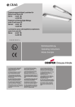
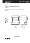
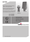
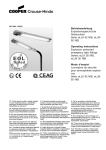
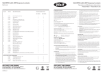
Betriebsanleitung
Explosionsgeschützte
Deckeneinbauleuchten
Operating instructions
Explosion Protected
Recessed Ceiling light
fittings
RLF 25...
CZ: "Tento návod k použití si mĤžete vyžádat
ve svém mateĜském jazyce u pĜíslušného
zastoupení spoleþnosti Cooper CrouseHinds/CEAG ve vaší zemi."
DK: "Montagevejledningen kan oversættes til
andre EU-sprog og rekvireres hos Deres
Cooper Crouse-Hinds/CEAG leverandør"
H: "A kezelési útmutatót az adott ország
nyelvén a Cooper Crouse-Hinds/CEAG cég
helyi képviseletén igényelheti meg."
I: "Se desiderate la traduzione del manuale
operativo in un´altra lingua della Comunit à
Europea potete richiederla al vostro
rappresentante Cooper Crouse-Hinds/CEAG"
P: "Se for necessária a tradução destas
instruções de operação para outro idioma da
União Europeia, pode solicita-la junto do seu
representante Cooper Crouse-Hinds/CEAG"
PL: Niniejszą instrukcjĊ obsáugi w odpowiedniej
wersji jĊzykowej moĪna zamówiü w
przedstawicielstwie firmy Cooper-CrouseHinds/CEAG na dany kraj.
LT: Šios naudojimo instrukcijos, išverstos Ƴ Jnjsǐ
S: "En översättning av denna montage- och
gimtąją kalbą, galite pareikalauti atsakingoje
"Cooper Crouse-Hinds/CEAG" atstovybơje savo skötselinstruktion till annat EU - språk kan vid
behov beställas från Er Cooper Crousešalyje.
Hinds/CEAG- representant"
LV: "Šo ekspluatƗcijas instrukciju valsts valodƗ
EST: "Seda kasutusjuhendit oma riigikeeles
SK: "Tento návod na obsluhu Vám vo Vašom
varat pieprasƯt jnjsu valsts atbildƯgajƗ Cooper
võite küsida oma riigis asuvast asjaomasest
rodnom jazyku poskytne zastúpenie spoloþnosti
Crouse-Hinds/CEAG pƗrstƗvniecƯbƗ."
Cooper Crouse-Hindsi/CEAG esindusest."
Cooper Crouse-Hinds/CEAG vo Vašej krajine."
FIN: "Tarvittaessa tämän käyttöohjeen käännös M: Jistgƫu jitolbu dan il-manwal fil-lingwa
nazzjonali tagƫhom mingƫand ir-rappreĪentant SLO: "Navodila za uporabo v Vašem jeziku
on saatavissa toisella EU:n kielellä Teidän
lahko zahtevate pri pristojnem zastopništvu
Cooper Crouse-Hinds/CEAG - edustajaltanne" ta' Cooper Crouse Hinds/CEAG f'pajjiĪhom.
podjetja Cooper Crouse-Hinds/CEAG v Vaši
doW(DQFUHLDVTHLPHWDMUDVKWZQRGKJLZQFUKVH NL: "Indien noodzakelijk kan de vertaling van
državi."
Z9VHDOOKJOZVVDWK9((PSRUHLQD]KWKTHLDSR deze gebruiksinstructie in een andere EU-taal
worden opgevraagd bij Uw Cooper CrouseWRQ$QWLSURVZSRWK9Cooper CrouseHinds/CEAG - vertegenwoordiging"
Hinds/CEAG?
E: "En caso necesario podrá solicitar de su
representante Cooper Crouse-Hinds/CEAG
estas instrucciones de servicio en otro idioma
de la Union Europea"
300 8000 2077 D/E (a)
Schaltplan Serie RLF 25..(18W, 36W, 58 W)
Wiring diagram series RLF 25..(18W, 36W, 58 W)
Schéma des connexions, série RLF 25..(18W, 36W, 58 W)
RLF 25018/18
RLF 25036/36
RLF 25058/58
Nur bei
Only
Seulement pour
luminaire à
RLF 250336
RLF 250358
Nur bei
Only
Seulement pour
luminaire à
RLF 250418
RLF 250436
RLF 250458
RLF 25...
Ausführung/
Version/Modèle
Spannungsbereich AC ± 10%/
voltage range AC ± 10%
Gamme des tensions CA ± 10%
Frequenzbereich/Frequency range
Gamme des fréquences
Spannungsbereich DC /
Voltage range DC
Gamme des tensions CC
kurzzeitige Überspannung AC/DC
Transient excess voltage AC/DC
Surtension transitoire CA/CC
Nennstrom in/A Rated current/A
Courant nom. en A avec:
230 V AC
220 V DC
2 x 18 W
(4 x 18 W)
110 - 254 V
2 x 36 W
(4 x 36 W)
110 - 254 V
2 x 58 W
( 4 x 58 W)
220 - 254 V
3 x 36 W
3 x 58 W
110 - 254 V
220 - 254 V
50 - 60 Hz
50 - 60 Hz
50 - 60 Hz
50 - 60 Hz
50 - 60 Hz
195 - 250 V
110 - 127 V 1)
110 - 250 V
195 - 250 V
110 - 250 V
195 - 250 V
0,53 (1,06)
0,54 (1,07)
0,52
0,53
0,80
0,81
<350 V
0,18 (0,36)
0,19 (0,37)
0,34 (0,68)
0,35 (0,69)
1) optional
2) zulässige Toleranzen gemäß EN 50014/max. permissable tolerances accd. EN 50014/Tolerances admissible selon EN 50014: ± 10 %
2
Cooper Crouse-Hinds GmbH
Montagebilder/Maßzeichnung
Illustrations for mounting/Dimensional drawing
1
2
3
4
3b
3a
5
8
12
1-4
9
6
7
10
11
13
Cooper Crouse-Hinds GmbH
3
1. Sicherheitshinweise:
Zielgruppe:
Elekrofachkräfte und unterwiesene Personen.
U Die Leuchte darf nicht in den Zonen 0 und 20
eingesetzt werden!
Die Anforderungen der EN 61241-0 und -1 u.a. in
Bezug auf übermäßige Staubablagerungen und
Temperatur, sind vom Anwender zu beachten.
U Die auf der Leuchte angegebenen technischen
Daten sind zu beachten!
U Umbauten oder Veränderungen an der Leuchte
sind nicht zulässig!
U Die Leuchte ist bestimmungsgemäß in
unbeschädigtem und einwandfreiem Zustand zu
betreiben!
U Als Ersatz dürfen nur Originalteile von Cooper
Crouse-Hinds (CCH)CEAG verwendet werden!
U Reparaturen, die den Explosionsschutz
betreffen, dürfen nur von CCH/CEAG oder einer
qualifizierten „Elektrofachkraft“ durchgeführt
werden!
U Lassen Sie diese Betriebsanleitung während des
Betriebes nicht in der Leuchte!
U Beachten Sie die nationalen Unfallverhütungsund Sicherheitsvorschriften und die nachfolgenden
Sicherheitshinweise, die in dieser Betriebsanleitung
) gekennzeichnet sind!
mit einem (
2. Normenkonformität
Diese Leuchte ist zum Einsatz in explosionsgefährdeten Bereichen der Zone 1,2, 21 und 22 gemäß EN 60079-10 und IEC 61241-10 geeignet.
Das eingebaute EVG 05 erfüllt die Anforderungen der
EN/IEC 60079-7 -4 Ausgabe (EOL) und den
Anforderungen der IEC 61347-2-3 (§17.2 und §17.3).
Sie wurde entsprechend dem Stand der Technik und
gemäß DIN EN ISO 9001:2000 entwickelt, gefertigt
und geprüft.
3. Technische Daten
EG-Baumusterprüfbescheinigung:
FTZÚ 06 ATEX 0050X
Kennzeichnung nach94/9/EG
II 2 G Ex de IIC T4
II 2 D Ex tD A21 IP65 T60 °C
Schutzklasse
nach EN 61140:
I
Schutzart nach EN 60529 IP65
zulässige Umgebungstemperatur
-20 °C bis +40 °C
Lagertemperatur in der
Originalverpackung:
-25 °C bis +60 °C
Lampenbestückung:
Zweistiftlampenfassung G13 nach
18 W
IEC 60081-22/20
36 W
IEC 60081-24/20
58 W
IEC 60081-21/22
Klemmvermögen Anschlussklemme 2x je Klemme:
4 mm²
Leiterquerschnitt bei Durchgangsverdrahtung:
2,5 mm2 für max. 16 A
Ex e-Kabel- und Leitungseinführung
Standardausführung:
M25x1,5 für Leitungen
Ø 8 bis 17 mm
Metall:
M20x1,5 Innengewinde
Prüfdrehmoment für Ex-e Kabel- und
Leitungseinführung M25x1,5: 5,0 Nm
Prüfdrehmoment für Druckschraube:
3,5 Nm
(für Abdichtung Leitung
oder Verschlussstopfen)
Prüfdrehmoment für ScheibenSchlitzschraube:
1,5 Nm
Gewicht
18/36/58 W (2-lampig):
ca. 6,9/ 12,9/ 17,2 kg
18/36/58 W (3-lampig):
ca. 7,5/ 13,4/ 17,8 kg
18/36/58 W (4-lampig):
ca. 9,5/16,5 /19,8 kg
4
Cooper Crouse-Hinds GmbH
4. Installation
Einsetzen der Lampe:
Verwenden Sie nur solche Lampen,
die für diese Leuchten zugelassen sind, siehe
Technische Daten und Typenschild!
T12-Lampen (Ø 38 mm) werden von der EOLSchaltung als fehlerhaft erkannt und abgeschaltet!
Achtung: Sicherheitstechnische Hinweise des
Lampenherstellers beachten
Öffnen und Schließen der Leuchte
U Die Schlitzschrauben mit geeignetem Schraubendreher lösen und Schutzscheibe abklappen, siehe
Bild 1 und 2.
U Achtung! Die Schutzscheibe ist nicht gegen
Herabfallen gesichert!
U Zum Schließen der Schutzscheibe Schrauben nur
handfest anziehen.(Prüfdrehmoment: 1,5 Nm)
Zweistiftsockellampe (G13)
Führen sie die Lampen in die Fassung ein. Drücken sie
dabei den Betätigungsknopf an der Fassung (Bild 3a).
Die Lampe muss fest in der Lampenfassung sein.
Prüfen sie den festen Sitz durch leichtes Ziehen an
der Lampe (Bild 3b).
Montageabmessungen: siehe Bild 13
5. Inbetriebnahme
Halten Sie die für das Errichten und Betreiben
von explosionsgeschützten elektrischen Betriebsmitteln geltenden Sicherheitsvorschriften gemäß des
Gerätesicherheitsgesetzes sowie die allgemein
anerkannten Regeln der Technik ein!
Transport und Lagerung der Leuchte ist nur in
Originalverpackung und angegebener Lage gestattet!
Deckeneinbau (Bild 12 und 13)
Beachten Sie die Maße für den Deckenausschnitt!
1. Gewindebohrungen an der Rückseite
M8 x 18 mm tief zur Deckenmontage.
2. Deckeneinbau in ausreichend tragfähige
Deckenkonstruktionen: seitliche Befestigungslöcher im Rahmen mit geeigneten Schrauben
befestigen (Option)
3. Montagebügel zur stirnseitigen Befestigung
(Option) siehe Bild 12
Verwenden Sie keine zu langen Schrauben!
Montagezubehör: s. Cooper Crouse-Hinds-Katalog.
Netzanschluss
U Hängen sie die Schutzscheibe aus den
Scharnieren aus.
U Lösen sie die 4 Befestigungsschrauben am
Reflektor um ca. 3 Umdrehungen (Bild 5, 6)
U Schieben sie den Reflektor nach rechts aus der
Schraube heraus und entnehmen sie den
Reflektor (Bild 7).
U Lösen sie die Schutzleiterverbindung am
Klemmstein oder am Gehäuse (Bild 8). Achten
sie auf die Position der Zahnscheibe (Schraubenkopf, Kabelschuh, Zahnscheibe
U Führen Sie die Leitung durch die Ex-Kabel- und
Leitungseinführung ein.
Bei Benutzung der CCH/CEAG Leitungseinführung
M25 (PA) verwenden Sie für Leitungen von 8 bis
12 mm beide Dichtungseinsätze, von 12 bis 17 mm
nur den äußeren Dichtungseinsatz.
Achten Sie auf korrekten Sitz des verbleibenden
Dichtungseinsatzes in der Verschraubung.
U Klemmen Sie die Leitungen an den Anschlussklemmen PE, N, L(Bild 10) gemäß Klemmenbezeichnung an (Bild 11).
U Schließen sie die Schutzleiterverbindung am
Gehäuse an (Bild 8,9).
U Führen sie den Reflektor in die 4 Befestigungsschrauben ein (Bild 7)
U Beim Schließen des Reflektors ist darauf zu
achten, dass keine Leitungen eingequetscht
werden.
U Ziehen sie alle 4 Schrauben fest an.
U Erst danach die Leitungseinführung fest
anziehen
U Hängen sie die Schutzscheibe in die Scharnierhaken ein.
U Führen sie die Lampen in die Fassung ein.
Drücken sie dabei den Betätigungsknopf an der
Fassung (Bild 3a). Die Lampe muss fest in der
Lampenfassung sein. Prüfen sie den festen Sitz
durch leichtes Ziehen an der Lampe (Bild 3b)
U Verschließen sie die Schutzscheibe mit den
Verschlussschrauben (Bild 1)
Achtung:
Bei nicht benutzten Kabel-und Leitungseinführungen
ist die Schutzscheibe zu entfernen und durch einen
Verschlussstopfen (Drehmoment 3,5 Nm) zu
verschließen.
Beim Verschließen mit einem Verschlussstopfen
stets beide Dichtungseinsätze verwenden!
Bei Metall-Kabeleinführungen sind die Schutzkappen
der nicht benutzten Einführungen zu entfernen und
durch bescheinigte Ex-Verschlussstopfen
(min. IP 66) zu verschließen!
U Überprüfen Sie vor der Inbetriebnahme die
korrekte Funktion und Installation der Leuchte in
Übereinstimmung mit dieser Betriebsanleitung
und anderen zutreffenden Bestimmungen!
U Führen Sie Isolationsmessungen nur zwischen PE
und Außenleiter L1 (L2,L3) sowie zwischen PE
und N durch!
- Messspannung: max. 1kV AC/DC
- Messstrom:
max. 10 mA
6. Instandhaltung
Halten Sie die für die Instandhaltung, Wartung
und Prüfung von explosionsgeschützten Betriebsmitteln geltenden Bestimmungen z.B. IEC 60079-17 ein!
Wartung:
Im Rahmen der Wartung sind vor allem die Teile, von
denen die Zündschutzart abhängt, zu prüfen z.B.:
U Gehäuse und Schutzglas auf Risse und
Beschädigungen.
U Dichtungen auf Beschädigungen.
U Klemmen und Verschlussstopfen auf festen Sitz.
Lampenwechsel:
U Beachten Sie für den Lampenwechsel die
Wechselintervalle gemäß Vorgabe der Lampenhersteller!
U Ein Lampenwechsel kann ohne Freischalten
vom Netz durchgeführt werden, da die
Fassungen beim Öffnen der Schutzwanne durch
einen allpoligen Trennschalter spannungsfrei
geschaltet werden.
Beachten sie jedoch, dass nationale Vorschriften oder lokale Anwendungsrichtlinien hiervon
abweichend sein können!
Instandsetzung
Vor dem Austausch oder der Demontage von
Einzelteilen ist folgendes zu beachten:
Schalten Sie das Betriebsmittel vor dem
Öffnen oder vor Instandhaltungsarbeiten erst
spannungsfrei!
Benutzen Sie nur von CCH/CEAG freigegebene
Ersatzteile!
Siehe Ersatzteilkatalog CCH/CEAG.
Programmänderungen und -ergänzungen sind
vobehalten.
Bei der Entsorgung nationale Abfallbeseitigungsvorschriften beachten!
Die Kunststoffmaterialien sind mit Materialkennzeichnungen versehen.
1. Safety instructions
For skilled electricians and instructed personnel in
accordance with national legislation, including the
relevant standards and, where applicable, in acc.
with IEC 60079-17 on electrical apparatus for
explosive atmospheres.
U The light fitting must not be operated in zone 0
and 20 hazardous areas!
U The requirements of the EN 61241-0 and -1
regarding excessive dust deposits and temperature
to be considered from the user.
U The technical data indicated on the light fitting
are to be observed!
U Changes of the design and modifications to the
light fitting are not permitted!
U The light fitting shall be operated as intended and
only in undamaged and perfect condition!
U Only genuine Cooper Crouse-Hinds (CCH)CEAG
spare parts may be used for replacement!
U Repairs that affect the explosion protection (see
national standard), may only be carried out by CCH/
CEAG or a qualified “electrician”!
U Do not keep these operating instructions
inside the light fitting during operation!
U The national safety rules and regulations for
prevention of accidents and the following safety
instructions which are marked with an ( ) in these
operating instruction, will have to be observed!
2. Conformity with standards
The light fitting is suitable for use in zone 1, 21, 2 and
22 hazardous areas acc. to EN 60079-10 and
IEC 61241-10.
The built-in EVG 05 fulfills the requirements of the
draft IEC 60079-7 Ed. 4 (EOL) and the IEC 613472-3 (§17.2 and §17.3).
It has been designed, manufactured and tested
according to the state of the art and according to DIN
EN ISO 9001: 2000.
3. Technical data
EC type examination
certificate:
FTZÚ 06 ATEX 0050X
Category of application:
II 2 G Ex de IIC T4
II 2 D Ex tD A21 IP65 T60 °C
Insulation class
EN 61140:
I
Degree of protection
accd. to en 60529
IP65
Permissable ambient
1)
-20 °C to +40 °C
temperatures
storage temperature in
original packing:
-25 °C to +60 °C
Fluorescent lamps
bi-pin lamps G13 accd.
18 W
IEC 60081-22/20
36 W
IEC 60081-24/20
58 W
IEC 60081-21/22
Supply terminal clamping capacity
2 x per terminal:
4 mm²
Conductor cross-section with
through-wiring:
2.5 mm2 for max. 16 A
EEx-e cable entry
standard version:
M25x1.5 for cable
Ø (8 to 17 mm)
metal thread:
M20x1.5
Test torque for M 25 x 1.5 Ex-e
cable entry:
5.0 Nm
Test torque for pressure
screw:
3.5 Nm (for sealing of the
cable or the blanking plug)
Test torque for cover pane
screw:
1.5 Nm
Weight
18/36/58 W (2-lampig):
ca. 6,9/ 12,9/ 17,2 kg
18/36/58 W (3-lampig):
ca. 7,5/ 13,4/ 17,8 kg
18/36/58 W (4-lampig):
ca. 9,5/16,5 /19,8 kg
4. Installation
The respective national regulations as well as the
general rules of engineering which apply to the
installation and operation of explosion protected
apparatus will have to be observed!
Transport and storage of the luminaire is permitted
in original packing and specified position only!
Opening and closing the light fitting
U unscrew the slotted screws on the cover pane
and open the pane (see fig. 1 and 2)
U Warning! The cover plane is not protected from
drop-down.
U To close the glass pane, press tightly onto the
luminaire housing and hand-screw (test torque
1.5 Nm)
Mounting dimensions: see fig. 13
Recessed ceiling installation: see fig. 12 and 13
Observe the correct ceiling cut-out!
1. For recessed ceiling installation threads are at
the rear side of the enclosure M8 x 18 mm
depth.
2. For recessed ceiling installation into sufficient
capable ceilings use mounting lugs of the
mounting frame with sufficient screws. (option)
3. A mounting bracket can be used for fixing at
the front/back end of the enclosure (option)
Do not use too long screws!
Accessories for mounting: See CCH/CEAG
catalogue.
Mains connection
U Dismount the cover plane from the hinges.
U unscrew the four fixing screws approx. 3 turns
at the reflector's (fig. 5, 6).
U Push the reflector rightwards out of the fixing
screw and take it out (fig. 7).
U Disconnect the protective earth connection from
the terminal or enclosure. Observe the correct
position of the toothed disk (screw head - cable
lug - toothed disk).
U Introduce the cable through the Ex cable entry,
see fig. 5. Use both sealing inserts for cables
from 8 to 12 mm, and the outer sealing insert
only for cables from 12 to 17 mm. Pay attention
to the proper fit of the remaining sealing insert
in the cable gland.
U Connect the conductors to the terminals PE, N, L
(fig. 10) in accordance with the terminal marking
(fig. 11)
U Connect protective earth to the enclosure (fig 8, 9)
U Insert the reflector into the 4 fixing screws (fig. 7)
U While closing the reflector protect wires from
squeezing in.
U Also tighten the 4 screws.
U Now tighten the cable entry.
U Insert the cover plane into the hinges.
U Insert the lamp into the lamp holder while
pressing the operating button (fig. 3a).
The lamp must be secure fixed in the lamp
holder. Check the correct position by slightly
pulling the lamp. (fig. 3b)
U Close the cover plane using the locking screws
(fig.1).
Attention
In case of unused cable entries, remove their
protective cover and close the entries with a
blanking plug (torque of 3.5 Nm). When closing the
gland with a blanking plug, always use both sealing
inserts! When metal cable entries are used, the
protective caps of the unused entries are to be
removed and the entries to be closed with certified
Ex blanking plugs!
(min. IP 66)
Fitting the lamps
Only use such lamps that have been certified for
these light fittings, see Technical data and type label!
T12-lamps (Ø 38 mm) will be detected as faulty and
will be cut off by the EOL-circuit
Note! Observe the safety instructions of the lamp
manufacturer!
Bi-pin lamp (G13)
The lamp is to be inserted to its stop into both holders, (fig.3a) so that both pins on either side of the
lamp engage in the holder.
Check the correct position by slightly pulling the
lamp. (fig. 3b)
5. Taking into operation
Prior to operation, check the light fitting for its
proper functioning and installation in compliance with
these operating instructions and other applicable
regulations!
Only carry out insulation measurements between PE
and the external conductor L1 (L, L2, L3) as well as
between PE and N.
– measuring voltage: max. 1 kV AC/DC
– measuring current:
max. 10 mA
6. Maintenance
Observe the national regulations applicable to the
maintenance, servicing and test of apparatus for
explosive atmospheres e.g IEC 60079-17 as well as
the general rules of engineering!
Servicing
When servicing, in particular those components that
affect the explosion protection, will have to be
checked, e. g.:
U Housing and cover pane for any cracks or damages.
U Gaskets for their perfect condition.
U Terminals and blanking plugs for their firm fit.
Lamp replacement
U Lamp replacement: Keep replacement intervals
as specified by the lamp manufacturer!
U Lamp replacement can be done without cut off
the luminaire from mains supply, because an all
pole switch will isolate the lampholders while
opening the protective bowl.
Notice: Observe national standards or directions
for use which can be divergent to this!
Repair
Prior to replacing or removing any components,
observe the following:
Cut the apparatus off the voltage before opening it
or carrying out repairs!
Only use certified genuine CCH/CEAG spare parts!
(See CCH/CEAG spare parts list).
Subject to alteration or supplement of this product
series.
Regarding waste disposal, observe the relevant
national regulations! The plastic materials are
marked with material identifications.
Cooper Crouse-Hinds GmbH
5
II 2 G Ex de IIC T4
II 2 D Ex tD A21 IP65 T60 °C
Cooper Cr
ouse-Hinds GmbH
Crouse-Hinds
Neuer Weg-Nord 49
D-69412 Eberbach
Phone +49 (0) 6271/806-500
Fax
+49 (0) 6271/806-476
Internet: www.CEAG.de
E-Mail: [email protected]
300 8000 2077/D/E/37.08/WE
Technische Änderungen vorbehalten!
Betriebsanleitung gültig ab 09.2008
(1026)