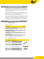
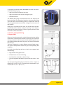
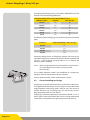
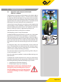
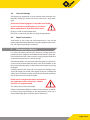
1
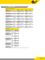
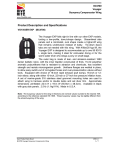
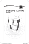
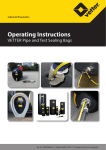
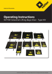
Emergency Pneumatics.
Operating Instructions
VETTER Lifting Bags 1.0 bar/14.5 psi
Article No. 9987013200 | © Vetter GmbH I 01/12 I Changes and errors excepted.
Vetter Lifting Bags 1.0 bar/14.5 psi
Contents
1. Important preliminary remarks. . . . . . . . . . . . . . . . . . . . . . . . . . . . . . . . . . . . 2
2. Description of the product. . . . . . . . . . . . . . . . . . . . . . . . . . . . . . . . . . . . . . . . 2
2.1
Scope of delivery. . . . . . . . . . . . . . . . . . . . . . . . . . . . . . . . . . . . . . . . . . . 2
2.2
Additional accessories. . . . . . . . . . . . . . . . . . . . . . . . . . . . . . . . . . . . . . 2
2.3
Application area. . . . . . . . . . . . . . . . . . . . . . . . . . . . . . . . . . . . . . . . . . . . 3
2.4
The VETTER construction. . . . . . . . . . . . . . . . . . . . . . . . . . . . . . . . . . . . 3
2.5
Correct handling and usage. . . . . . . . . . . . . . . . . . . . . . . . . . . . . . . . . 5
2.6
Safety instructions. . . . . . . . . . . . . . . . . . . . . . . . . . . . . . . . . . . . . . . . . . 6
3. Preparing the product for use. . . . . . . . . . . . . . . . . . . . . . . . . . . . . . . . . . . . . 7
3.1
Preparations for operation. . . . . . . . . . . . . . . . . . . . . . . . . . . . . . . . . . 7
3.2
Application instructions. . . . . . . . . . . . . . . . . . . . . . . . . . . . . . . . . . . . . 7
4. Operating Instructions. . . . . . . . . . . . . . . . . . . . . . . . . . . . . . . . . . . . . . . . . . . . 8
4.1
Operation with compressed air bottle 200 bar or 300 bar. . . . . 8
4.2
Operation with other air supplies. . . . . . . . . . . . . . . . . . . . . . . . . . . . 9
4.3
Care and storage. . . . . . . . . . . . . . . . . . . . . . . . . . . . . . . . . . . . . . . . . . 10
4.4
Repair instructions. . . . . . . . . . . . . . . . . . . . . . . . . . . . . . . . . . . . . . . . . 10
5. Elimination of defects. . . . . . . . . . . . . . . . . . . . . . . . . . . . . . . . . . . . . . . . . . . . 10
6. Repetitive checks. . . . . . . . . . . . . . . . . . . . . . . . . . . . . . . . . . . . . . . . . . . . . . . . 11
7. Technical data . . . . . . . . . . . . . . . . . . . . . . . . . . . . . . . . . . . . . . . . . . . . . . . . . . . 12
EC Conformity Declaration. . . . . . . . . . . . . . . . . . . . . . . . . . . . . . . . . . . . . . . . . . 13
Page 1/14
1.
Important preliminary remarks
Only knowledge and the exact observance of this operating manual guarantee correct and reliable operation, achieve the best
possible usage and ensure any claims made within the framework
of the Vetter guarantee.
Only a person who has been instructed in the use of Vetter Lifting
Bags, using the manufacturer operating manual and the instructions from the user, is to be given the operation task.
The operating instructions given here are to be regarded as part
of the product and are to be kept for the complete life duration of
the product. In case the product should be passed on to a successive user then the operating instructions must also be included.
2.
Description of the product
2.1
Scope of delivery
Inventory check: Items
Description
Qty.
Lifting bags, of the same type and size
2
Inflation hoses, 5 m (16.4 ft.) in length
2
Dual deadman controller
1
Pressure regulator 200/300 bar
1
Packing bag
1
Set repair material
1
Operating instruction
1
Other set combinations are possible if required!
2.2
Additional accessories
Pos. Article No.
Description
1
1600 0105 00 Comp. air bottle 10 l / 200 bar
2
1600 0091 00 Comp. air bottle 6 l / 300 bar
3
1600 0199 00 Comp. air bottle 9 l / 300 bar
4
1600 0084 00 Dual connector 200 bar
5
1600 0091 00 Dual connector 300 bar
Page 2/14
Vetter Lifting Bags 1.0 bar/14.5 psi
6
1600 0145 00 Pressure regulator
7
1600 0120 00 Adapter for compressor
2.3
Application area
Due to the high pressure point load, it is frequently not possible
to use winches or hydraulic lifting gear when dealing with heavy,
unstable loads. In such cases the advantages of Vetter lifting bags
become very much apparent:
99 Very light 99 Low pressure point loading
99 Very flat in design
99 Can be used in any position
As already known, air distributes itself evenly on all sides. The ideal shape of a pressure container is spherical. With flexible pressure
containers, such as the lifting bag, the top and bottom as well as
sides bulge.
With lifting bags this bulging, especially of the top and bottom,
could damage the bag when pressed against sharp objects and
the bag may become cut, punctured or abraded.
Danger of damage to the
pressurized walls of the bag.
2.4
The VETTER construction
Bags which have a cylinder shape cannot bulge on the side because the material tensions evenly. This characteristic greatly reduces any damage to the side wall.
Owing the extensive use of internal harnesses, bulging of the top
and bottom is avoided. The strong, multi-layer and reinforced material avoids bag damage within the working area.
The supporting material of the lifting bag is made of ARAMIDE
which is a very light but tear-resistant artificial fibre. The coating
of the supporting material is made of NEOPRENE which is a synthetic artificial rubber.
Page 3/14
As opposed to material rubber, NEOPRENE has ideal characteristics for the lifting bag, e.g.:
99 High resistance to mineral oil and acid
99 High resistance to wear and has a long life cycle
99 Maintenance free
The flexible lifting bags mould themselves to the shape of the
load to be lifted as opposed to hydraulic and pneumatic lifting
gear with their solid positioning plates. In connection with the
very low application pressure of only 1.0 kg/cm², loads can be lifted carefully.
Lifting bags, irrespective of the type, are unstable over the complete lifting distance! When using just one bag it must be positioned exactly under the load‘s centre of gravity otherwise load
movement cannot be avoided.
In practise, exact positioning
is not possible!
If the use of one bag cannot be avoided then positioning stability
of the load is to be ensured. However, if two bags are used and if
one bag is placed to the front part and the other bag to the rear
part of the load then the centre of gravity will always be between
the two bags.
The basic condition for a stable, different control of both bags is
the separate independent control using the corresponding dual
controller.
Due to this, the Lifting Bags 0.5 bar and 1.0 bar are equipped with
the following:
2 Bags of the same type and size
2 Inflation hoses 5 m and 10 m long
1 Dual deadman controllers 1.0 bar/14.5 psi
1 Pressure regulator 200/300 bar (special version for US, F and
J)
The corresponding packing bag is included as well as 1 repair set.
Lifting bags 1.0 bar/14.5 psi are subject to the requirements specified in DIN 14 152 T 1 (EN 13 731).
Page 4/14
Vetter Lifting Bags 1.0 bar/14.5 psi
According to DIN, lifting bags are classified as PNEUMATIC LIFTING
DEVICES with the following definitions:
Pneumatic lifting devices according to DIN 14 152 T 1
DIN-Description
Sidewall
Min. lift / kN
LH 10 S
Yes
10
LH 20 S
Yes
20
LH 30 S
Yes
30
LH 50 S
Yes
50
LH 10
No
10
LH 20
No
20
The following Vetter lifting bags correspond to the listed standard
types:
Standard
Vetter Lifting Bags 1.0 bar/14.5 psi
LH 10 S
1/6
LH 20 S
1/9
LH 30 S
1/13
LH 50 S
1/23
Pneumatic lifting device or lifting bag without side wall can be
supplied if required. As opposed to the old national standard DIN
14 152 T 1, the European standard DIN EN 13 731 requires the
following with a controller:
5.2.4.6 When the operating device of a controller is released then it must immediately return to the „neutral „ position automatically.
The so called „deadman switch“ was introduced as a compulsory
fitting to meet the requirements of this standard.
(Picture: Dual controller 1.0 bar with deadman switch.)
2.5
Correct handling and usage
Lifting bags are mainly pneumatically (usually with air) driven rescue equipment for the rescue services (e.g. fire service) with which
trapped people can be freed, paths made to carry out rescue or
counter-measures etc. The lifting bags can also be used as working equipment to lift or move objects.
Lifting bags meet the requirements specified in DIN EN 13 371 as
well as GUV-G 9102 in the field of fire services. Further operational
instructions are specified in the operating manual of the user.
Page 5/14
2.6
Safety instructions
The prespecified protective clothing is to be worn during the operation.National regulations connected with the lifting bag systems
and their operation are to be observed.
Lifting bags are only to be used with compressed air. Under no
conditions are inflammable or aggressively acting gases to be
used. The lifting bags must only be inflated with original Vetter
fittings because these are subjected to an acceptance test by the
manufacturer. The lifting bag system is to be checked before and
after operation to determine whether it is in perfect condition.
Never lay two or more lifting bags
on top of each other.
Ensure that the load does not slip. Gravitationally support loads
being lifted during a continuous lifting procedure. Always pay
particular attention to the stable condition of the support material during support work.
The support structure must at least support
the whole area of the bag and must be larger
in its length and width than in its height!
Attention danger of slipping! Never place
metal on metal when carrying out support work
Place stones, branches or similar items under the bag in order to
increase ground grip when the ground is slippery (ice, snow, mud
etc.). Avoid pointed loads such as grips, screws etc.
Never place the bags on sharp edges or hot to red hot components. Use suitable intermediate layers and cover the whole
bearing area of the bag.
Protect the bag from sparks from welding or separation work.
Do not additionally subject the bag to such things as hydraulic
stamps, hoists, falling loads etc.
Never remain under the load being lifted,
and never try to grip the load from below!
Remain at a safe distance!
Avoid shearing effects caused by bag squeezing when deflating.
Never stand in front of the load during operation, always place
yourself to the side of it, because the bag can be catapulted out
under unfavourable conditions.
Page 6/14
Vetter Lifting Bags 1.0 bar/14.5 psi
3.
Preparing the product for use
3.1
Preparations for operation
Remove the set of lifting bags from the transport and unpack the
packing bag. Make certain that the inflation device is ready for
operation. Make certain that there is sufficient air supply available.
Only perfectly working and tested lifting bag
systems are to be used.
The person in charge of the operation is to decide on the method
and how it is to be applied from case to case within the field of his
responsibility as well as observance of the operating instructions
of the user.
3.2
Application instructions
Move the lifting bag to a suitable position so that at least 75% of
the supporting bag surface is under the load.
Normally at least two bags are used of the same type and size. Position each bag near to the end of the load. If necessary use lines
for drawing under the load or lower between loads which have to
be pressed apart.
Depending on the low operation pressure
of the lifting bags, the maximum pressure
point loading is only:
1,0 kg/cm² with lifting bags 1.0 bar
Due to low bearing pressure, under-support for ground fixture is
only necessary in exceptional cases.
The load to be lifted is to be secured
against slipping by suitable measures !
Before moving the lifting bag under the load it should be ensured
that the side wall material is positioned between the top and bottom plates. Under no circumstances should the side wall material
be between the load and top or the load and bottom during the
lifting sequence. This can, under certain circumstances, cause damage to the side wall of the bag.
If the movement height or the movement area is not sufficient for
correct application of the lifting bag, then the required space can
normally be quickly obtained by using the Vetter Mini Lifting Bag
8 bar.
Page 7/14
4.
Operating Instructions
4.1
Operation with compressed air bottle 200 bar or 300 bar
Connect the pressure reducer to the compressed air bottle, 200 bar
or 300 bar, using the tommy screw (1). Close the presser reducer
(2). Open the valve on the bottle (3). The pre-pressure manometer
(4) indicates the pressure in the bottle. Adjust the back pressure to
approximately 2 bar with the regulation bar (5) (indication of the
reduced pressure on the back pressure manometer (6)).
3
4
6
2
1
5
9
Connect the air hose of the pressure reducer via the nipple to the
input coupling (7) of the controller. In doing this, press the nipple
into the coupling until you feel it lock in. For additional safety: turn
the brass sleeve (8) so that it is opposite the safety pin (9).
8
Open the hand wheel (3) of the pressure reducer.
The lifting bag system is ready for operation.
To inflate the lifting bag pull the lever (12) back, resp. slowly open
the ball valve (10). Observe the manometers (11) and the load.
If the required pressure is reached for lifting or if the lift height is
achieved, then end the inflation sequence by releasing the switch
lever or close the ball valve. The switch lever of the controller with
the deadman switch will automatically go back to the zero position.
7
11
12
12
An integrated safety valve will automatically activate when the
bag is unintentionally over-inflated above the maximum operating pressure (1.0 bar/14.5 psi) or when there is an increase in bag
pressure due to additional loading of the bag.
The activation tolerance for opening and closing of the safety valve must not exceed +/- 10%.
Press the switch lever to „Deflate“ in order to deflate the bag or to
lower the load.
Load behaviour and lift movement must always be continuously
monitored. Depending on the type, position and behaviour of the
load during the lifting sequence, the lifting bags are either
99 simultaneously and evenly inflated or
99 inflated step-by-step, resp. individually.
Remember to remain at a safe distance from
the load! Do not stand directly in front of
the lifting bags because if the positioning
is incorrect the bags could be catapulted
outwards.
Page 8/14
Vetter Lifting Bags 1.0 bar/14.5 psi
Never leave the controller and the inflation device unattended
while the lifting bags are under pressure. Never disconnect the
connection between bags and controller while the bags are under
pressure.
4.2
Operation with other air supplies
Amongst others, the set of transition pieces (Art. No.: 1600 0125
01) with the following adapters are available for operation with
other air sources:
8
5
9
3
4 6 7
2
10
1
1. Truck compressed air connection, dual brake system.
For tapping air out of the trailer coupling head.
2. Dummy coupling Seals off the control line of the brake system
Remember! Ensure that the truck does not roll, use brake
blocks!
3. Truck tyre inflation device adapter
For tapping off air from the so-called tyre inflation bottle near
the brake.
Remember! The tyre inflation connection must be ensured by a safety valve as a standard (blow-off pressure approximately 7.5 bar)!
4. Truck tyre valve
Inflation with a normal hand or foot pump as well as other air
supplies for tyre inflation.
5. Truck tyre valve connection, can be clamped For extracting air for the spare tyre.
6. Adapter for the local air pressure network.
7. Adapter Construction-site compressor
8. Air supply hose, 10 m, green.
9. Air supply hose, 10 m, green, with blocking valve.
10. Case, red
Page 9/14
4.3
Care and storage
The lifting bag equipment is to be cleaned each time after use.
Normally cleaning is made with warm water and a soap detergent.
A chemical cleaning agent is not to be used under
any circumstances and high pressure warm
water equipment is also never to be used.
Drying is made at room temperature.
DIN 7716 is to be observed with any long storage periods.
4.4
Repair instructions
Small cracks or cuts in the side wall material (max. 4 cm) can be
quickly repaired without difficulty using the supplied repair material. See separat operating instructions.
5.
Elimination of defects
If a safety valve blows-off too early because a foreign body has
penetrated and is lodged in, then the blow-off device is to be opened at the head of the safety valve by turning counter-clockwise
so that the compressed air is able to escape.
If the foreign body is not removed, then the upper part of the valve must be unscrewed with the safety valve disassembled. To do
this position the tube pliers in the centre and unscrew by turning
to the left.
Carefully remove the valve ball and remove the foreign body.
Screw the upper part of the valve tightly back and assemble the
safety valve, and check to make certain that it functions perfectly.
The set pressure must not be changed.
If the seal or seal plate has been removed on
the upper part of the valve then reliable
function is not guaranteed.
The safety valve is to be exchanged.
If there are functional defects on the pressure reducer or controller due to icing, high humidity at low temperatures, then use a
normal defrosting agent (similar to that used on cars).
Page 10/14
Vetter Lifting Bags 1.0 bar/14.5 psi
6.
Repetitive checks
Repetitive checks are to be made on lifting bag systems as
follows:
99 Testing during acceptance
Check to ensure that all items are present and complete; this
is made by the person commissioned for the task. A visual and
function test is to be made by an instructed person according
to the operating instructions.
99 A visual and function test is to be made after each period of
use / application and carried out by an instructed person. This
test is to be documented.
99 The lifting bag system is to undergo a visual test and function
test at least once each year by a trained person and is to be
made according to the check list in the following pages. This
test is to be documented.
99 Every 5 years, or if there is any doubt about the safety or reliability, the lifting bag is to be tested according to GUV-G 9102
(formally GUV 67.13) by the manufacturer.
The responsibility for the correct and professional execution of
the repetitive test lies with the user!
Lifting bags or lifting bag systems are not subject to the
requirements specified in EC Guidelines 97/123/EC (refer
to Section 3.15).
A repetitive test by a specialist (e.g. TÜV or DEKRA) is no longer
necessary.
Page 11/14
7.
Technical data
Lifting bag 1.0 bar/14.5 psi
Type
1/23
1/13
1/9
1/6
DIN Nomination
LH 50 S
LH 30 S
LH 20 S
LH 10 S
Lifting power
to/US tons 11.3/12.45
6.5/7.15
4.5/4.95
3.0/3.3
Lifting power set
to/US tons 22.6/24.9
13.0/14.3
9.0/9.9
6.0/6.6
Lifting height, max.
cm/inch
110/43
62/24
60/24
45/18
Insertion height
(uninflated)
cm/inch
3/1.2
3/1.2
3/1.2
3/1.2
Diameter
cm/inch
120/47
91/36
76/30
61/24
Working pressure
bar/psi
1.0/14.5
1.0/14.5
1.0/14.5
1.0/14.5
Test pressure
bar/psi
1.5/21.75
1.5/21.75
1.5/21.75
1.5/21.75
Air requirement
at 1.0 bar
l/cu.ft.
2,486/88
806/28
544/19
262/9
Nominal content
l/cu.ft.
1,243/44
403/14
272/9.6
131/4.6
Inflation time, approx. sec.
191
62
42
20
Weight, approx.
kg/lbs
21/46
12/26
9/20
7/15
Weight (set), approx.
kg/lbs
58/128
40/88
32/71
25/55
Rescue Set
Lifting power
to/US
tons
Lifting height
cm/inch 65/26
Working
pressure
bar
1.0
psi
14.5
bar
1.5
psi
21.75
Air requirement
at 1.0 bar
l
2,164
cu.ft.
76.39
Nominal content
l
1,082
cu.ft.
38.19
cm
110 x 72 x 30
inch
43 x 28 x 12
Inflation time
sec.
164
Weight, approx.
kg/lbs
25.0/55.1
Test pressure
Packaged size
12.1/13.3
All rights reserved for technical changes within the scope of product improvement.
Page 12/14
Vetter Lifting Bags 1.0 bar/14.5 psi
EC Conformity Declaration
in accordance with Directive 2006/42/EC
Manufacturer name and address:
Vetter GmbH A Unit of IDEX Corporation
Blatzheimer Str. 10 - 12
53909 Zülpich
We hereby declare, that the VETTER Lifting Bags 1.0 bar/14.5 psi for lifting and lowering loads
Type:
______________
Serial No.: ______________
Model:______________
(see appliance plate, to be entered by customer)
meets the following relevant provisions:
Directive 2006/42/EC on Machinery
Applied harmonised standards, references to which have been published in the Official Journal of
the European Union:
DIN EN ISO 12100
EN 13731
Applied national standards and technical specifications:
Authorised representative for the compilation of technical documents:
Vetter GmbH A Unit of IDEX Corporation
Blatzheimer Str. 10 - 12
53909 Zülpich
This EC Conformity Declaration was issued:
Zülpich, 10.01.12
(Place, Date, Signature)
Page 13/14
(Identification of signatory)
Place your trust in emergency pneumatics!
We are the company who can help you, find a solution to your problem!
Vetter GmbH
A Unit of IDEX Corporation
Sales Germany
International sales
Blatzheimer Str. 10 - 12
D-53909 Zülpich
Germany
Tel.: +49 (0) 22 52 / 30 08-50
Fax: +49 (0) 22 52 / 30 08-70
Mail: [email protected]
Tel.: +49 (0) 22 52 / 30 08-60
Fax: +49 (0) 22 52 / 30 08-71
Mail: [email protected]
www.vetter.de
Article No. 9987013200 | © Vetter GmbH I 01/12 I Changes and errors excepted. I Made in Germany