1
Operating Instructions
Translation of the original operating instructions
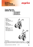
Power Mower
5400
5400 KL
5400 with
l Planetary Mowing Attachment
Stroke 85 mm, Crank Stone 45 mm
l Mountain brake
Engines:
l 4-Stroke, Robin EH 17
l 4-Stroke, Robin EH 25
5400 KL with
l Planetary Mowing Attachment
Stroke 85 mm, Crank Stone 45 mm
or:
Double-Knife Mowing Attachment
Stroke 60/24 mm
l Steering Brake Clutch
l Central Brake
l 4-Stroke-Engine, Robin EH 25
5143, 5146, 5321
&
Before commissioning the machine, read operating
instructions and observe warnings and safety instructions.
Operating Instructions No. 998 765-B 10.11
Symbols, Name Plate
Please complete:
Symbols
Warning – Danger
Machine Type No.:
..................................................
Identification No.:
..................................................
Engine Type:
..................................................
Engine No.:
..................................................
Date of Purchase: .....................
Important information
Choke
Fuel
Oil
Glue
Engine Start
Engine Stop
Engine oil level
Air filter
For name plate, refer to
page 3, figure A/14;
page 7, figure C/14
Air cooling
For engine type and number, refer
to page 66, figure E/13
Visual check
Please state these data when
ordering spare parts to avoid
wrong deliveries.
Clutch
Only use original agria spare
parts!
Wheel drive
Transmission oil level
Specifications, figures and dimensions stated in these instructions are
not binding. No claims can be derived from them. We reserve the right
for improvements without changing
these instructions.
This delivery comprises:
l Operating instructions
l Power mower
l Tool kit
Mowing drive
Forward
Reverse
PTO
Brake
Tyre air pressure
Open (unlocked)
Closed (locked)
Clockwise
Anti clockwise
è
- Serviceç
= contact your agria workshop
2
agria Power Mower 5400
Designation of Parts
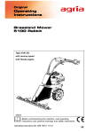
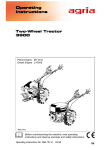
Figure A
5400 with planetary mowing drive
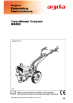
Figure B
5400 Steering Handle
agria Power Mower 5400
3
Designation of Parts
Figure A
5400 with planetary mowing drive
1
2
3
4
5
6
7
9
11
12
13
14
15
Grass distributor / knife driver
Mowing drive hood
Eyelet for assist rope
Tool kit
Steering handle
Cutter bar
Planetary mowing drive
Gearbox - oil filler plug, dipstick
Wheel flange
Hexagonal nut for wheel flange fixing (on both sides)
Gearbox - oil drain plug
Name plate / machine identification no.
Engine
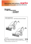
Figure B
5400 Steering Handle
1
2
3
4
5
6
8
9
10
11
4
Hand lever for engine stop
Safety Circuit
Hand lever for clutch and mountain brake
Pawl for hand clutch lever
Locking screw for steering handle height adjustment
Shifter for wheel drive 1st and 2nd speed
Shifter for mowing drive OFF / ON
Speed control lever
Pawl for forward and reverse shifting
Hand lever for forward and reverse
agria Power Mower 5400
Index
Symbols, Name Plate ....................... 2 4. Commissioning and
Operation
Designation of Parts
Machine, Steering Handle 5400 ....... 3 Commissioning the Machine ..........
Machine, Steering Handle 5400 KL . 7 Starting the 4-Stroke-Engine ..........
Robin-Engine EH 17, EH 25 ........... 66 Switching off the Engine .................
Mowing ............................................
1. Safety Instructions ........ 9 - 13 Danger Zone ...................................
Due Use ............................................ 9 Operation on Slopes .......................
32
34
35
36
37
37
1
2
5. Maintenance
2. Specifications
Gearbox ..........................................
Mowing Drive ..................................
Vibration Acceleration Value ...........
Track Width Plan .............................
Robin Engine EH 17 D ...................
Robin Engine EH 25 D ...................
Operation on Slopes ................. 17,
Noise Levels ............................. 17,
14
14
14
16
17
18
18
18
3. Devices and Operating
Elements
Engine ............................................. 19
Hand Lever for Engine Stop ........... 20
Safety Circuit .................................. 20
Clutch .............................................. 21
Mountain Brake ............................... 21
Gearbox .......................................... 22
Single Wheel Steering Brake Clutch 23
Steering Handle Adjustment .......... 24
Loading Eye .................................... 24
Planetary Mowing Attachment ....... 25
Double-Knife Mowing Attachment 26
Knife Attachment Removal ............. 27
Knife Attachment Mounting ............ 28
Running Bases, Extra Weights ....... 29
Wheel Locking Bolts ....................... 30
Extra Drive Wheels ......................... 30
Strake Wheels, Snow Chains ......... 30
Twin-Wheels ................................... 31
Differential Hubs ............................. 31
4-Stroke-Engine ....................... 38 - 42
Air Filter .................................... 39, 40
Machine ................................... 43 - 47
Safety Circuit .................................. 46
Hand Lever Adjustment .................. 47
Mountain Brake ............................... 48
Planetary Mowing Attachment ....... 49
Double-Knife Mowing Attachment 50
Cutter Bar ....................................... 51
Re-Grinding Mowing Knives ........... 51
General Maintenance, Cleaning ..... 52
Storage ........................................... 53
3
4
Accessories for Cutter Bar ... 54 - 55
6. Troubleshooting ........... 56 - 57
5
Varnishes, Wear Parts .................. 58
Diagram: Electric Circuit .............. 58
Lubrication Charts ................. 59 - 61
Inspection and Maintenance
Chart ............................................... 64
EC Conformity Declaration .......... 67
Recommendations ......................... 6
Note foldout pages!
Fig. A and B .............................. 3
Fig. C and D .............................. 7
Fig. E ....................................... 66
agria Power Mower 5400
5
6
Recommendations
Fuel:
Lubricants and AntiCorrosive Agents:
Use the specified lubricants for engine
and gearbox (see “Specifications”).
We recommend using bio- lubricating oil or bio-lubricating grease for
“open” lubricating points or nipples (as
specified in the operating instructions).
We recommend using bio-slushing
oil for preservation of machines and
implements (do not apply on painted
external covers). Oil can be brushed
or sprayed on
Anti-corrosive agents are environmentally friendly and degrade fast.
Using ecologically safe bio-lubricants
and bio-anti-corrosives, you contribute to environmental protection and to
the wellbeing of humans, animals and
plants.
This 4-stroke engine runs smoothly
on commercial unleaded regular and
supergrade petrol (including E10)
as well as Super plus.
Do not add oil to petrol.
If, for environmental reasons, you
use unleaded petrol, make sure the
fuel is drained completely when shutting down the engine for more than
30 days. This is to prevent resin residue from depositing in the carburettor, fuel filter, and tank. Or add a fuel
stabilizer.
For further instructions refer to “Engine Preservation”.
Maintenance and Repair:
The trained mechanics of your agria
workshop carry out expert maintenance and repair.
You should only carry out major maintenance work and repairs on your own,
if you have the proper tools and knowledge of machines and internal combustion engines.
Do not hammer against the flywheel
with a hard object or metal tools as it
might crack and shatter in operation
causing injuries and damage. Only
use suitable tools for pulling the flywheel.
6
agria Power Mower 5400
Designation of Parts
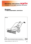
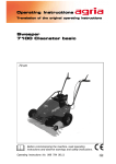
Figure C
5400 KL with planetary mowing drive
5400 KL with double-knife mowing drive
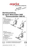
Figure D
5400 KL
steering handle
agria Power Mower 5400
7
Designation of Parts
Figure C
With planetary mowing drive and double-knife mowing drive
1
2
3
4
5
6
7
8
9
10
11
13
14
15
Grass distributor / knife driver
Mowing drive hood
Eyelet for assist rope
Tool kit
Steering handle
Cutter bar
Planetary mowing drive
Double-knife mowing drive
Gearbox - oil filler plug, dipstick
Collar for steering brake clutch Bowden cable
Wheel flange with steering brake clutch
Gearbox - oil drain plug
Name plate / machine identification no.
Engine
Figure D
Steering handle
1
2
3
4
5
6
7
8
9
10
11
13
14
15
16
8
Engine-off circuit
Safety circuit lever
Clutch hand lever
Pawl for clutch hand lever
Locking bolt for steering handle height adjustment
Shifter for wheel drive 1st and 2nd speed
Locking bolt for steering handle lateral adjustment
Shifter for mowing drive OFF / ON
Speed control lever
Pawl for F-R shifting
Hand lever for F-R shifting
Hand lever for steering brake clutch left
Hand lever for steering brake clutch right
Hand lever for central- and park brake
Pawl for park brake
agria Power Mower 5400
1. Safety Instructions
Before starting the engine, read the operating instructions and note:
Warning
General Instructions on
Safety and Accident
Prevention
Basic Rule:
This symbol marks all paragraphs which
affect your safety. Pass all safety instructions to other users and operators.
The standard accident prevention regulations must be adhered to, as well as
all other generally accepted rules governing operational safety, occupational
health and road traffic regulations.
Due use
For drives on public roads, the national
traffic code applies.
The power mower is constructed solely
for the cutting of grass and similar plants
as well as thin non-wooded scrub in land
& forest management, green spaces,
and other such areas and may also be
used as a snow-clearing machine after
it has been fitted with a suitable rake
blade (due use).
Accordingly, check the power mower for
road and operational safety each time
you take up operation.
Any other type of operation is considered undue. The manufacturer is not liable for any damages resulting from
undue use, for which the risk lies with
the user alone.
When the power mower is used on public roads, the local national road traffic
rules must be observed, e.g. reflectors,
lights.
The power mower is not intended for use
with a trailer on public roads or as as a
tractive machine.
Due use includes compliance with
manufacturer’s instructions on operation, maintenance and repair.
Only persons familiar with the mower
and instructed on the hazards of operation are allowed to use, maintain and
repair the mower.
Teenagers of 16 years or younger may
not operate the power mower!
Only work in good light and visibility.
Operator’s clothes should fit tight. Avoid
wearing loose fitting clothes. Wear solid
shoes.
Note the warning and instruction signs
on the mower for safe operation. Compliance is for your own safety.
When transporting the mower on vehicles or trailers outside the area to be
mowed, ensure that the engine is turned
off.
Careful with rotating tools – keep at a
safe distance!
Any unauthorized changes to the mower
render manufacturer liability null and
void.
agria Power Mower 5400
9
1
1. Safety Instructions
1
Beware of coasting tools. Before you
start any maintenance or repair on them,
wait until tools have come to a complete
stop.
Foreign powered parts shear and crush!
Riding on the attachment during operation is not permitted.
Implements and their weight affect the
driving, steering, braking, and tip-over
characteristics of the mower. Therefore,
ensure steering and braking functions
are sufficient. Match operating speed to
conditions.
Do not change settings of governor. High
engine speed increases risk of accidents.
Operation and Safety
Devices
Before You start the Engine
Become familiar with the devices and
operating elements and their functions.
Above all, learn how to turn the engine
off quickly and safely in an emergency.
Ensure that all protective devices are
mounted and positioned to provide protection.
With no implement mounted, make sure
PTO-shaft is covered with the protective cap.
Starting the Engine
Working Area and
Hazardous Area
Do not start engine in closed rooms. The
carbon monoxide contained in the exhaust fume is extremely toxic when inhaled.
The user is liable to third parties working within the mower’s working range.
Before you start the engine set all operating elements to neutral or idling position.
Staying in hazardous area is not permitted.
For starting the engine, do not step in
front of the mower and the implement.
Check the immediate surroundings of
the mower before you start it. Watch out
for children and animals.
Do not use assist-starting liquids when
using electrical assist-starting devices
(jumper cable). Danger of explosion!
Before you start work, clear the area
from any foreign object. During operation, always watch out for further objects
and remove them in time.
Operation
For operation in enclosed areas, ensure
that a safety distance is kept to enclosures to prevent damage to tools.
Never leave the operator’s position at
the steering handle while mower is at
work.
Never adjust the operating handles during work – danger!
During operation the operator must keep
at a distance as defined by the steering
handle, especially when turning the machine.
10
agria Power Mower 5400
1. Safety Instructions
Riding on the implement during opera- Secure mower and implements against
tion or in transport is not permitted.
rolling off (parking brake, wheel chocks).
If clogging occurs in the implement, turn Beware of injuries while coupling impleoff the engine and clean the implement ments.
with an appropriate tool.
Fit implements as specified and only
In case of damage to the power mower couple at specified points.
or to the implement, immediately turn Secure mower and implement against
off the engine and have it repaired.
unauthorized use and rolling off when
If steering causes problems, immedi- you leave the machine. If necessary, inately bring the mower to a halt and turn stall transport or security devices and
it off. Have the malfunction removed secure.
without delay.
Mowing attachment
To prevent the mower from sliding on
slopes, make sure it is secured by another person using a bar or a cord. This
person must be located at a higher position than the vehicle and at a safe distance from the attachment at work.
Handle with care! Sharp blades of the
cutter bar may cause injuries! Remove
protective knife strips only for mowing
and refit immediately after work has finished.
For transport and storage always fit the
If possible, always work horizontally on
protective knife strips. Secure finger
the slope!
bars additionally with tension springs.
End of Operation
Do not transport the dismounted cutter
Never leave the mower unattended with bar without protective strips.
the engine running.
Before fitting and dismounting the cutBefore you leave the power mower, turn ter bar, make sure all blades are prooff the engine.
tected by the protective strip.
Secure power mower against unauthor- To exchange the mowing knife and to
ized use. If mower is equipped with ig- fit/dismount the knife driver, make sure
nition key, remove the key. For all other that you turn screws away from cutting
versions, remove spark plug connector. edges.
For grinding the mowing knives, always
wear safety goggles and gloves.
Implements
Only fit implements with the engine and
PTO switched off.
Always use appropriate tools and wear
gloves when changing implements and
parts thereof.
For fitting and dismounting implements
bring support leg into proper position
and ensure stability.
agria Power Mower 5400
11
1
1. Safety Instructions
Weights
1
Storage
Always fit weights onto appropriate
weight fitting devices.
Snow clearing
Ensure snow dozer is mounted correctly! Wear slip-proof shoes.
When swivelling the snow dozer watch
out for crush and shear points. Adjust
working speed to conditions. Operator
may be injured when the mache comes
in contact with solid objects.
Maintenance
Never carry out any maintenance or
cleaning with the engine running.
Before you work on the engine, always
remove spark plug connector (petrol engine only).
Check regularly and, if necessary, replace all protecting devices and tools
subject to wear and tear.
Replace damaged cutting tools!
Always wear safety gloves and use proper
tools when exchanging cutting tools!
It is not allowed to store the mower in
rooms with open heating.
1
Never park the mower in closed rooms
with fuel left in tank. Fuel vapours are
hazardous.
Engine, Fuel and Oil
Never let the engine run in closed rooms.
Extreme danger of intoxication! For the
same reason, also replace damaged exhaust pipe immediately.
Caution with hot engine parts!
The exhaust and other engine parts
become very hot, if the engine runs and
immediately after turning off. Hold for
sufficient distance from hot surfaces and
keep children away from the running
engine.
Be careful when dealing with fuel. Great
danger of fire! Never refill fuel close to
open fire, inflammable sparks or hot engine parts. Do not refill fuel in closed
rooms. Do not smoke when refilling!
Do not carry out repairs like welding,
grinding, drilling, etc. on structural and
safety-relevant parts (e.g. steering handle, coupling devices)!
Refill only with the engine switched off
and cooled down.
Keep mower and implement clean to
avoid risk of fire.
In case of fuel spillage, pull the power
mower away from the spillage before
you start the engine.
Check nuts and screws regularly for tight
fit and re-tighten, if necessary.
After maintenance and cleaning, ensure
that you reinstall all safety and protective devices and adjust them properly.
Only use original agria spare parts.
All other commercial spare parts must
correspond to quality and technical requirements specified by agria.
12
Do not spill any fuel, use a proper filling
device.
Make sure fuel is of specified quality.
Store fuel in approved cans only.
Store anti-corrosive agents and stabilizing liquids out of reach of children. If
sickness and vomiting occur, see a doctor. If fuel has contacted eyes, rinse
them thoroughly, avoid inhaling of vapours.
agria Power Mower 5400
1. Safety Instructions
Read and observe enclosed instructions.
Before you dispose of opened and
seemingly empty pressurised tins (e.g.
of assist-starting liquids) make sure they
are completely empty. Empty them in
ventilated places safe from spark formation or flames. If necessary, dispose
of tins in hazardous waste deposits.
Be careful when draining hot oil, danger of burns.
Explaining of Warning
Signs
1
Before any cleaning, maintenance, and
repair work switch off the engine and
pull spark plug connector.
Make sure oil is of specified quality. Storage is in approved cans only.
Dispose of oil, greases, and filters separately and properly.
With engine running, keep at a safe distance from cutting tools!
Tyres and Tyre Air
Pressure
Signs
When working on tyres, make sure
power mower is parked properly and
secured against rolling off.
Any repairs are to be carried out by
trained mechanics only and with the
appropriate tools.
Regularly check tyre air pressure. Excessive pressure may cause bursts.
When working with the
machine, wear individual
protective ear plugs.
Wear protective gloves.
Wear solid shoes.
Use appropriate tyre air pressure when
fitting weights or implements.
Re-tighten attachment bolts of drivewheels or check tightness when doing
maintenance work.
Electrical System
Persons having a pacemaker must not
touch live parts of ignition system when
the engine is running!
agria Power Mower 5400
13
2. Specifications
Type: ........................................... 5400
Dimensions [mm]
Tyre: ........................... 4.00-8 field tyre
..................... optional 5.0-10 field tyre
Tyre air pressure: ................... 1,5 bar
........... optional 16 x 6.50-8 Terra Grip
Tyre air pressure: ................... 0,8 bar
2
Weight (with fuel tank filled up): ..................
............... with engine EH 17 105,5 kg
............... with engine EH 25 108,5 kg
(without cutter bar)
Clutch: ............................. Cone clutch
Gearbox: ........... Mechanical gearbox,
F-R reversing gear
2 forward speeds and 2 reverse
speeds Mountain brake
Filling quantity: ............ approx. 2,0 l.
Transmission oil SAE 90-API GL5
(e.g. BP Energear Hypo)
2
a
b
e
h
l
m
S
A
=
910
=
620
=
490
= ca. 990
= 1490 (
)
= >1330 } depending on work with
= refer to track width plan
= }
Mowing drive
l Centrally driven oil bath rocker
arm mowing drive
Travel Speeds (km/h)
for universal, municipal cutter bar and
cutting bar
Stroke: ..................................... 85 mm
4.00-8
5.0-10
16x6.50-8
1.
2,2
2,6
2,2
2. 1.
3,4 2,2
4,0 2,6
3,4 2,2
2.
3,4
4,0
3,4
Steering handle: ....... rubber mounted
height adjustable.
Crank Stone: ............................ 45 mm
Grease
Only use lithium based grease K2 DIN
51502.
Recommendation: DEA "Paragon EP1",
Mobilgrease MB2, Glisando EP2, ARAL
HL2 or LF2, ESSO Beacon EP2.
Vibration acceleration value:
on handlebar grip
Planetary mowing drive . ahw = 16 m/s2
in accordance with EN 12733
14
agria Power Mower 5400
2. Specifications
Type: ..................................... 5400 KL
Dimensions [mm]
Tyre: ........................... 4.00-8 field tyre
..................... optional 5.0-10 field tyre
Tyre air pressure: ................... 1,5 bar
........... optional 16 x 6.50-8 Terra Grip
Tyre air pressure: ................... 0,8 bar
Weight (with fuel tank filled up): ..................
.................. (without cutter bar) 149 kg
Double knife
mowing drive
Clutch: ............................. Cone clutch
Gearbox: ........... Mechanical gearbox,
F-R reversing gear
2 forward speeds and 2 reverse speeds
Single-wheel steering brake clutch
Central brake
optional: Safety hillholder
Planetary
mowing
drive
a =
740
910
b =
740
740
e =
500
500
h =
approx. 990
approx.920
Filling quantity: ............ approx. 1,8 l.
Transmission oil SAE 90-API GL5
(e.g. BP Energear Hypo)
l
=
1320
m =
>1330
Travel Speeds (km/h)
S =
A =
>1330
(depending on work with) (depending on work with)
} refer to track width plan
Mowing drive (alternatively)
4.00-8
5.0-10
16x6.50-8
1.
2,2
2,6
2,2
2. 1.
3,4 2,2
4,0 2,6
3,4 2,2
2.
3,4
4,0
3,4
Steering handle:
Anti-vibration steering handle bearing (2-axlesteering handle bearing - Licenser is
Frauenhofer Gesellschaft zur Förderung der
angewandten Forschung e. V. (German society for the promotion of applied research.)
l Centrally driven planetary mowing drive
for universal, municipal cutter bar and
cutting bar
Stroke ...................................... 85 mm
Crank Stone: ............................ 45 mm
Grease
Only use lithium based grease K2 DIN
51502.
Height-adjustable; side-adjustable without tools.
Recommendation: DEA "Paragon EP1",
Mobilgrease MB2, Glisando EP2, ARAL
HL2 or LF2, ESSO Beacon EP2.
Vibration acceleration values:
on handlebar grip
with planetary mowing drive ...............
...................................... ahw = 7,3 m/s2
with double knife mowing drive ..........
...................................... ahw = 5,3 m/s2
l Centrally driven double-rocker
mowing drive
for double-knife cutter bar
(Holding German patent)
Stroke: Top knife ...................... 60 mm
Bottom knife ................ 24 mm
in accordance with EN 12733
agria Power Mower 5400
15
2
2. Specifications
Track Width Plan [mm] Power Mower 5400
2
A
1)
S
i
A
A
4.00-8 AS
525 415 305
970
220 )1
950
5.0-10 AS
575 430 285
1025
220 )1
1050
16 x 6,50 - 8
630 465 300
= Intermediate flange 5519 011
Track Width Plan [mm] Municipal Power Mower 5400 KL
A
S
i
A
S
i
A
4.00-8 AS
645 535 425 1074
220 )6 1005
5.0-10 AS
695 550 405 1105
220 )6
755 590 425
16x6.50-8 TG
21x11.00-8 TG
90 )2 970 690 410
2)
= Intermediate flange 5616 511
3)
= Intermediate flange 5519 031
16
A
agria Power Mower 5400
2. Specifications
4-Stroke Engine EH 17
Starter: .......................... Recoil starter
Fuel tank capacity: ...... approx. 3,6 l.
Manufacturer: ........................... Robin
Type: ..................................... EH 17 D
Version:
Fan-cooled 1-cylinder 4-stroke engine
(petrol)
Bore: ........................................ 67 mm
Stroke: ..................................... 49 mm
Cubic capacity: ................... 172 ccm
Output: ............. 4,0 kW at 3600 min -1
Torque:
.................. max. 11 Nm at 2600 min -1
Spark plug: ............. BOSCH WR7AC
NGK BR 6 HS
Electrode gap: 0,6 - 0,7 mm
Ignition system:
Contactless electronic magnet
ignition, ignition point is preset, radio
remote, screened according to VDE
0879
Valve lash (engine cold)
Intake .......................... 0,08 - 0,11 mm
Outlet .......................... 0,08 - 0,11 mm
Fuel: ......................... unleaded petrol,
refer to fuel recommendations
Air filter: .................. Dry filter element
with foamed preliminary filter
Carburettor: ... horizontal throttle float
carburettor
Mixture Control Screw:
Base setting approx. 1 3/8 revs. open
Rated speed: ................... 3600 min -1
Top no-load speed: ......... 4000 min -1
Idling speed: .................... 1200 min -1
Engine oil: .................. Filling quantity
approx. 0,65 l.
Multi-grade oil SAE 10 W-40 API-SC
or higher quality
Operability on Slopes:
Engine is suited for use on slopes
(with oil level at “max” = upper level
mark):
Continuous operation possible up to
45° inclination (100%)
Noise level:
with planetary mowing drive
In accordance with EN 12733 appendix B:
Noise level at operator’s ear ...............
....................................... LP= 90 dB(A)
In accordance with 2000/14/EU,
appendix III, part B, chapter 32 lawn
mower:
Acoustic power level: ..........................
.................................. LW= 105,7 dB(A)
agria Power Mower 5400
17
2
2. Specifications
4-Stroke Engine EH 25
Carburettor: ... horizontal throttle float
carburettor
Manufacturer: ........................... Robin
Mixture Control Screw:
Base setting approx. 1/4 revs. open
Type: ..................................... EH 25 D
2
Version:
Fan-cooled 1-cylinder 4-stroke engine
(petrol)
Rated speed: ................... 3600 min -1
Bore: ........................................ 75 mm
Idling speed: .................... 1200 min -1
Stroke: ..................................... 57 mm
Engine oil: .................. Filling quantity
..................................... approx. 0,65 l.
Multi-grade oil SAE 10 W-40 API-SC
or higher quality
Cubic capacity: ................... 251 ccm
Output: ............ 5,9 kW at 3600 min -1
Torque:
............... max. 16,7 Nm at 2400 min -1
Spark plug: ............. BOSCH WR7AC
NGK BR 6 HS
Electrode gap: 0,7 - 0,8 mm
Ignition system:
Contactless electronic magnet
ignition, ignition point is preset, radio
remote, screened according to VDE
0879
Top no-load speed: ......... 4000 min -1
Operability on Slopes:
Engine is suited for use on slopes
(with oil level at “max” = upper level
mark) Continuous operation possible
up to 45° inclination (100%)
Noise level:
with double knife mowing drive 125 cm
In accordance with EN 12733 appendix B:
Valve lash (engine cold)
Intake .......................... 0,08 - 0,11 mm
Outlet .......................... 0,08 - 0,11 mm
Noise level at operator’s ear ...............
....................................... LP= 88 dB(A)
Starter: .......................... Recoil starter
In accordance with 2000/14/EU,
appendix III, part B, chapter 32 lawn
mower:
Fuel tank capacity: ......... approx. 5 l.
Fuel: ......................... unleaded petrol,
refer to fuel recommendations
Air filter: .................. Dry filter element
with foamed preliminary filter
Acoustic power level: ... LW= 101 dB(A)
with planetary mowing drive
In accordance with EN 12733 appendix B:
Noise level at operator’s ear ...............
.................................... LP= 96,4 dB(A)
In accordance with 2000/14/EU,
appendix III, part B, chapter 32 lawn
mower:
Acoustic power level: ..........................
.................................. LW= 106,6 dB(A)
18
agria Power Mower 5400
3. Devices and Operating Elements
The power mower agria type 5400 is
suited for all common applications and
tasks in farming and forestry and for winter service operation.
Available attachments:
l Cutter bars in different versions and
work widths.
l Snowplough
l For a choice of further attachments,
e.g. strake wheels, refer to our pricelist.
Cooling system is fan-cooled. Therefore
keep grille at recoil starter and cooling
fins of cylinder clean and free from
sucked-in plant trash.
Idling speed
Always ensure that idling-speed is adjusted correctly. At low speeds and with
the speed control lever set to idle, the
engine is supposed to run smoothly and
without run-out.
Air filter
Engine
The four-stroke petrol engine runs on
commercial petrol (refer to fuel recommendations p 6).
During the first 20 operating hours
(break-in period) do not use engine to
maximum power. Even after break-in
period never use engine at higher
speed than necessary for the work in
hand.
High engine speed is harmful to
any engine and considerably
affects its durability. This applies especially for no load operation. Any
overspeed (have the engine roar) can
result in immediate damage.
I
Cooling system
The air filter purifies the air taken in. A
clogged filter affects engine output.
Ignition system
The engine is equipped with a maintenance-free, contactless electronic ignition system. We recommend to have
necessary checkups done by an expert
only.
Speed control lever
The speed control lever (B/9 or D/9) on
the steering handle is for stepless control of engine speed from min = IDLING
GAS to max = FULL THROTTLE to fit
requirements.
agria Power Mower 5400
19
3
3. Devices and Operating Elements
Engine-off-switch
The power mower is equipped with an
electric off-switch (B/1 or D/1) On pressing the switch, the ignition is turned on
or off (engine is switched off).
B/1
D/1
Position "I"
=
Operation
Position "0"
=
Engine off
The engine-off-switch also
serves as emergency-off-switch.
Set the switch to “0” for fast switch-off!
I
3
Safety Circuit
B/2
D/2
STOP
B/4
D/4
B/3
D/3
l Stop position:
When releasing the security lever (B/2 or
D/2), the ignition system is switched off
lever, the ignition system is switched off
(engine is off).
- Beware! engine keeps running due to
centrifugal mass.
l Start position:
For starting the engine and for short
breaks, pull the hand clutch lever (B/3
or D/3) and fasten with pawl (B/4 or D/4).
l Operating position: To operate the
machine press safety lever (B/2 or D/2).
Do not fasten safety lever.
W
I
Release the safety lever for fast
engine switch-off. The lever
automatically goes to STOP position.
20
agria Power Mower 5400
3. Devices and Operating Elements
Clutch / Mountain Park
Brake
Clutch
Power Mower 5400
The operation of the dry bevel clutch is
via the hand clutch lever (D/6).
l The mais deD/3 chine
coupled when
you pull the
hand lever to
position "0",
the engine
D/4
stops driving
the mower.
l The pulled hand lever can be locked
with pawl (D/7).
Operation of clutch and mountain park
brake is via the hand lever (B/3).
The mountain park brake serves to stop
and to change gears on slopes.
l The mais deB/3 chine
coupled when
you pull the
hand lever to
position "0",
the engine
B/4
stops driving
the mower.
l The pulled hand lever can be locked
with pawl (B/4).
l When You
keep pulling
the hand lever,
the mountain
park brake is
engaged.
Power Mower 5400 KL
l Watch for the correct clutch play to avoid clutch slipping away during operation.
47
With engine running, don't park mower with hand
clutch lever pulled for a longer period, this may
damage the clutch.
With engine stopped, always park mower with hand clutch
lever pulled (pawl locked in place). Otherwise, clutch problems may result due to corrosion.
I
agria Power Mower 5400
21
3
3. Devices and Operating Elements
Gearbox
I
Only change gears with machine
decoupled and engine stopped!
FR-Change
The mower is equipped with a 2-gear
reversing transmission. In both gears
F/R drive is possible.
Move F/R-hand lever (B/11 or D/11)
down (pawl B/10 or D/10 is unlocked)
= the power mower travels forward.
B/10
D/10 B/11
D/11
3
Move hand lever up
= the power mower travels reverse.
B/11; D/11
In centre position (pawl is locked)
= the machine is in neutral.
I
The machine can be pushed in F/R
neutral.
Gear-Change
Change gears 1 – 2 via shifter (B/6 or
D/6)!
1st gear = shifter pushed forward
2nd gear = shifter pulled backward
B/6
D/6
I
There is no neutral position
Engaging Mowing Drive
B/8; D/8
22
l Mowind drive shifter (B/8 or D/8)
pushed forward
= mowing drive engaged
l Mowind drive shifter pulled backward
= mowing drive disengaged
agria Power Mower 5400
3. Devices and Operating Elements
Version 5400 KL
Single-Wheel Steering
Brake Clutch
For easy turning, the power mower is
equipped with an easy-use steering
brake clutch for both wheels.
D/14
To turn right, pull the hand lever
(D/14). The right drive-wheel decelerates and the power mower turns right
with forward speed engaged.
To turn left, pull the hand lever
(D/13).
D/13
W
5
When turning on banks, always
turn the machine towards the
slope.
Central Brake
The combined central / park brake
serves to decelerate and park the power
mower on banks.
Central Brake
D/15
Swivel excentric lever (D/12) backwards
- both drive-wheels are decoupled and
decelerate.
Release excentric lever and the lever
swivels back to original position – brake
is released.
Park Brake
D/16 D/15
Swivel excentric lever (D/12) backwards
beyond the dead centre. Eccentric lever automatically comes to a stop - both
drive-wheels are decoupled and
blocked.
To release park brake, swivel eccentric
lever back to original position – brake is
released.
agria Power Mower 5400
23
3
3. Devices and Operating Elements
Steering Handle Height
Adjustment
Do never adjust operating
handles during working
– risk of accidents!
W
l Unfix ball handle levers
side until the detents
on either
are free.
l Bring left and right steering handle to
the desired height and introduce into the
respective detent.
3
l Tighten ball handle levers
5400
again.
Eyelet for Loading
For transport facilities and for fixing
A/3
the security rope when working on
slopes, the power mower 5400 is
equipped with a hook (A/3) and the 5400
KL with an ring (C/3).
Do not use any loading devices with
sharp edges (e.g. sharp-edged hooks,
eyelets etc.).
Never walk or remain
under moving loads.
Danger!
5400 KL
Fixing Points
C/3
For towing away, recovering and tying down and to ensure a safe transport, use the
fixing points
24
at the hook (A/3) or eyelet (C/3) and engine
food guard.
agria Power Mower 5400
3. Devices and Operating Elements
Planetary Mowing
Attachment
Required cutter bars:
Item no. 5547 011 - 5547 821
(depending on version)
Centrally driven planetary mowing
drive
Accessories for cutter bar::
Stroke: ..................................... 85 mm
Crank stone ............................. 45 mm
Running bases
Grass distributor
54,55
Mounting Cutter Bar
M 8 = 23 Nm
Switch off engine,
Remove spark plug
connector!
Wear safety
gloves!
1 Mount the knife driver
onto the cutter bar.
M12 = 76 Nm
1a
a) Universal-SC- and
Municipal cutter bar
(Pos. 3 - 6)
1b
b) Finger cutter bar
(Pos. 7 - 9)
3
1
2
3
4
5
6
7
8
9
10
11
12
13
14
15
16
17
Mower hood
Planetary mowing drive
Hex bolt M 8 x 22; 2 x
Hex bolt M 8 x 16; 2 x
Wedge washer; 4 x
Knife driver for Universal- and Municipal
cutter bar
Hex bolt M 8 x 20; 2 x
Wedge washer; 2 x
Knife driver for finger cutter bar
Grass distributor
Wedge washer; 2 x
Hex bolt M 8 x 16; 2 x
Hex bolt M12 x 30; 4 x
Ball spring ring; 4 x
Hex nut M12; 4 x
Cutter bar
Knife guard
The cutter bar is exposed to
extreme strain. Therefore, it evidently must be maintained and adjusted
with special care.
I
2 Mount the cutter bar
(16) onto the planetary
moving drive (2).
- Universal- and finger
cutter bar
(Pos. 13 - 15)
- Municipal cutter bar
(Pos. 13 - 14)
3 Mount the grass distributor (10).
2
Dismounting the cutter bar
In reverse order.
Exchanging Mowing Knives
Refer to operating
instructions cutter bar
W
Switch off engine, Remove
spark plug connector!
Wear safety gloves!
agria Power Mower 5400
25
3
3. Devices and Operating Elements
Single Rocker Mowing
Drive
3
1
2
3
4
5
Mower hood
Upper rocker
Lower rocker
Knife driver
Cutter bar
Cutter Bar Assembly
W
27
45 Nm
4x
Switch off engine, Remove
spark plug connector!
Wear safety gloves!
Remove both knives (see page 27).
Place the cutter bar onto the centring sleeves (6).
l Attach the cutter bar to the cutter bar
carrier using bolts (7) and washers (8) tighten evenly at 45 Nm.
Mount the mowing knives
(see page 28).
Dismounting the cutter bar is in reverse
order.
26
28
agria Power Mower 5400
3. Devices and Operating Elements
Mowing Knife Removal
W
Switch off engine, Remove
spark plug connector!
Wear safety gloves!
Fold up pivot arms.
Loosen clamping bolts.
3
Grab top knife with both hands and
pull out to the front. Pull with little tipping movements.
Lift bottom knife out of pivot arms.
Use a screw driver or similar tool. Pull
with little tipping movements.
Before you put down bothmowing knives, mount knife
guard!
W
agria Power Mower 5400
27
3. Devices and Operating Elements
1
2
3
4
5
6
Knife driver
Link pin
Knife with link pin fitted
Clamping bolt
Spring washer
Hex head bolt
Mowing knife attachment
W
Switch off engine, Remove
spark plug connector!
I
Only fit straight and sharp
knives.
Wear safety gloves!
Loosen clamping bolts (4 - 6) all
3
the way. Then remove the link pins
(2).
Insert the link pin (2) into the
knife driver (1) on the bottom and
the top knife.
Fold up the upper pivot arms.
Fit the bottom knife (3) with link
pin fitted into the catch on the lower
rocker.
l Lock all mushrooms in the bottom pivot arms
l Fit the top knife with link pin fitted into the catch on the upper
rocker.
Mount the clamping bolts (4 -
Messerpilz
6) of the link pins.
Fold the pivot arms into place
and lock them onto the mushrooms
on the knife.
l Check top and bottom knives for
even gliding and smooth contact.
Check the bottom knife and the knife
support in the same way.
Tighten the clamping bolts at 100
Nm.
Tighten the clamping bolts
at 100 Nm to secure the link
pins holding the top and bottom
knives after fitting the mowing
knives and before each
operation!
I
28
agria Power Mower 5400
3. Devices and Operating Elements
Cutter Bar Running Bases
There are height-adjustable running
bases to prevent the cutter bar from
being damaged by stones, etc. during
operation. This specification depends
on the cutter bar version or is optional
equipment.
Height adjustment:
l Loosen hex nuts (1).
l Lift the cutter bar off the ground and
adjust the running base (2) to the desired height.
3
l Retighten hex nuts (1).
1 Hex head nuts
2 Running bases
I
Set all running bases to the same
height.
Extra weights for cutter bars
1
2
3
4
Additional weight
Hex head bolt
Hex head nut
Spring washer
Optional: item no. 5547 931
If the cutter bar is not heavy enough for
slope operation (this applies in particular to the Universal cutter bar), it is possible to replace the outer skids by extra
weights (item no. 5547 931).
In addition, a second pair of extra
weights can be attached in place of the
running bases. This takes a long hex
head bolt M 8 x 45.
agria Power Mower 5400
29
3
3. Devices and Operating Elements
Wheel Attachment Bolts
A
B
A: Version hex head bolt with ball spring ring
B: Version double-end stud with ball spring
ring and hex head nut
100 Nm
Damp the short threaded end of double end
studs with LOCTITE 270 or UHU-Plus and
screw tightly into wheel flange respectively
hub adapter.
l Fit the countersunk side of the ball spring
ring into countersink-type holes of disc wheel
l Tighten the wheel attachment bolt respectively the wheel
nuts at 100 Nm
Drive-Wheels
3
For full tractive power, mount wheels with pointed parts of lugs
showing in travel direction (wheels seen from above).
Extra Wide Drive-Wheels
Item no. 5490 611: 16×6,50 - 8 Terra Grip
Usage: Mowing on soft (boggy) ground
Snow Chains
When working with snow chains fitted on wheels, observe
manufacturer’s instructions, make sure there is sufficient clearance between chains and machine parts.
100 Nm
We recommend using strake wheels
or twin wheels for operation on extremely steep slopes.
I
Strake wheels
Item 5417 511 for drive-wheels 4.00-8
Item 5517 521 for drive-wheels 5.0-10
1
2
3
4
6
7
8
9
Double-end stud
Ball spring ring
Flange
Hex head nut
Strake wheel
Tommy screw
Snap ring
Spring
30
l Wheel attachment bolts version B must
be fit
l Fit drive-wheels with flanges (3) and ball
spring rings + ball spring rings between
wheel bowl and flanges (centring)
l Fit strake wheels (6) on hexagonal full dog
points and tighten with tommy screws (7).
l Make sure that wheel carriers point to
machine, when looked into travel direction (see fig.).
l Block the tommy screw by positioning the spring (9).
agria Power Mower 5400
3. Devices and Operating Elements
Loctite 270
1
2
3
4
6
10
5616 511
Double-end stud
Ball spring ring
Wheel nut
Wheel track expansion
Anti-winding tube
Ball spring ring
l use wheel attachment bolts version B.
l Mount the internal drive wheels on
the wheel hubs of the basic machine.
l Mount the wheel track expansion
device (4) on the wheel bowl with ball
spring rings ( 2) + ball spring rings between wheel bowl and wheel track expansion (centring).
l Mount the outer drive wheels on the
wheel track expansion.
100 Nm
11 Wheel att. bolt
3
5519 011
11
1
2
3
4
5
6
7
8
9
10
11
50 h
Twin wheels with wheel track
expansion
6
Double-end stud
Ball spring ring
Wheel nut
Differential hub
Flange
Thrust washer
Snap ring (Seeger circlip ring)
Lubrication nipple
Ball spring ring
Wheel attachment bolt
Anti-winding tube
100 Nm
Twin wheels with Differential
Hubs
l use wheel attachment bolts version B.
l Mount the internal drive wheels on
the wheel hubs of the basic machine.
l Mount the differential hubs (4) on the
wheel bowl with ball spring rings ( 2) +
ball spring rings between wheel bowl
and differential hub (centring).
l Fit the anti-winding tubes (11) onto
the differential hubs.
l Mount the external drive wheels to
the differential hubs.
Lubrication
l Lubricate the wheel flange lube nipple (8 or 3 ) at intervals of 50 operating
hours or after cleaning with a pressure
washer. Use a grease gun (Bio lubrication grease).
Differential
position
Setting
l The machine is supplied with differential hubs being set to give differential
action.
l Rigid position
1
2
3
4
Rigid
Differential hub
Flange
Lubrication nipple
Snap ring (Seeger
circlip ring)
Remove snap ring (4) with a pair of pliers.
Position the wheel flange (2) with the
tang nocken between both tang pins and
fit the snap ring.
agria Power Mower 5400
31
3
4. Commissioning and Operation
Commissioning
Please note that durability and operational safety of the engine depend to a large
extent on its breaking-in. Always allow a cold engine to warm up for some minutes and never run it at full throttle at the beginning.
Please note: for the first 20 hours of operation (break-in period) do not use the
engine at full power.
Make sure you check and maintain air filters regularly and use clean fuel.
Only use branded petrol.
Only use fresh, clean fuel (not older than 3 months) and approved fuel cans to be
purchased in special shops. Rusty sheet metal cans or fuel cans not suited for
petrol are not permitted.
For the first commissioning or after longer periods of no operation, fill fuel tank to
maximum to avoid starting problems.
Be careful when dealing with fuel.
Fuel is easily inflammable and explosive in certain conditions!
4
l Do not refill in closed rooms.
l Before each fuel fill, shut off the engine and
wait until it has cooled off.
l Never refill close to open fire, inflammable
sparks or hot engine parts.
l Do not smoke during filling!
l Do not spill any fuel, use a proper filling device.
Do not cause fuel tank to overflow, but leave a 5
mm margin for the fuel to expand.
l Check transmission oil level (see page 43)
I
Note: For reasons of transport, the engine
is not filled completey with engin oil!
Before you operate the engine the first time,
fill in engin oil (see page 38)!
32
agria Power Mower 5400
4. Commissioning and Operation
Before starting the engine
? ok
? ok
Sufficient fuel is filled into the tank?
Air filter clean?
39/40
? ok
Check the engine oil level
38
Check the transmission oil level
? ok
43
Grease the crank stone (planetary
mowing drive)
49
Check all bolts and nuts for tight fit 4
52
? ok
Only take power mower into
operation with all protective
devices mounted and positioned to
provide protection!
W
Careful when starting the engine in
closed rooms!
Ensure good ventilation and fast escape of exhaust fumes. Exhaust
fumes contain carbon monoxide
which acts toxic when inhaled.
Do not touch the hot engine – danger of burns!
Do not touch or remove the ignition line and spark plug connector
while the engine is running.
agria Power Mower 5400
33
4. Commissioning and Operation
Starting the
4-Stroke-Petrol-Engine
Position the spark plug connector.
Open fuel tap (E/3).
EH 17
CHOKE
l Cold engine: Turn CHOKE lever
(E/5) to position "CHOKE".
EH 25
4
l Warm engine: Leave CHOKE in operating position or turn half way.
Set engine-off-switch (B/1 or D/1) to
operating position ("I").
Set speed control lever (B/9 or D/9)
1/3
to approx. 1/3 throttle.
Position hand clutch lever to start
position (lock pawl (B/4 or D/4)).
Pull the starter rope on the handle
(E/6) until the starter clutch engages.
Then pull hard and fast to pull the rope
all the way out. After the start, let the
rope glide back. Do not let it snap back.
EH 17
EH 25
As soon as the engine has warmed
up, move the CHOKE back to the operating position (if it was operated).
34
agria Power Mower 5400
4. Commissioning and Operation
Shutting off the Petrol
Engine
Set speed control lever to idle posi-
tion "min" and let engine run idle for
approx. half a minute.
min
6 30 sec
Set engine-off-switch to "0"
Close the fuel tap.
4
Secure the machine against unauthorised use. Remove the sparkplug connector.
Engine-off-switch (B/1 or D/1)
also serves as emergency offswitch. If necessary, set switch to “0” to
turn engine off.
I
To down the machine for a long
period of time, do not press the
engine shut-off-switch to stop the engine. Instead, close the fuel tap and operate the engine until it comes to a stop
by lack of fuel. This is to ensure the carburettor is empty and to avoid resin deposits.
I
agria Power Mower 5400
35
4. Commissioning and Operation
Mowing
Grease the crank stone
(Planetary mowing drive)
Remove knife guard..
Grease the cutter bar.
Start the engine.
2. 1.
è
èComissioning
Check safety circuit function
- only operate the machine if the
safety circuit is working.
W
Wear protective ear plugs and solid
shoes.
I
Engage proper gear.
Engage mowing drive.
Engage wheel drive.
Pull hand clutch lever slightly while
4
pressing the throttle.
è
0
I
After mowing and in case of
grass clogging:
Move F/R hand lever to “neutral” , The
mower comes to a stop but not the knives,
thus freeing the cutter bar from grass.
Disengage mowing drive.
Shut engine off.
Refit knife guard.
For direction change from forward to
reverse, proceed as follows:
Engine to idle speed.
Pull hand clutch lever and hold.
Move the shifter to "R" and hold.
Slowly release the hand clutch lever while you are pressing the throttle.
Re-tighten all nuts and screws of the mowing drive and the
cutter bar after commissioning and when changing the knife
after about 15 - 30 operating minutes and than every 4 operating hours (particularly of the cutter bar carrier, knife driver
and cutter bar mounting flange).
36
agria Power Mower 5400
4. Commissioning and Operation
Caution with hot engine parts!
Danger zone
The exhaust and other engine parts
become very hot, if the engine runs
and immediately after turning off. Hold
for sufficient distance from hot
surfaces and keep children away from
the running engine.
Danger Zone
Keep out of the mower’s danger zone during starts and
operation.
W
Mowing on Slopes
To prevent the mower from
sliding on slopes, make sure it
is secured by another person using a bar or a cord. This person must
be located at a higher position than
the vehicle and at a safe distance
from the attachment at work.
W
4
Mowing on
plain surfaces
Mowing on
slopes
Starting the engine on slopes
è
For operation on banks, always turn
machine towards the slope!
I
2. 1.
Keep the mowing drive and the
travelling drive in engaged mode; braking effect.
Move the hand clutch lever and
emergency-off-switch to "Start" position.
Start the engine.
agria Power Mower 5400
37
4
5. Maintenance: 4-stroke engine
I
Apart from observing all operating instructions , it is also important to pay
attention to the following maintenance instructions.
Please note:
Only do all maintenance work with the engine switched off and
spark plug connector disconnected!
When working on mowing knives, wear safety gloves!
Engine
6 A; 8 h
Check Oil Level
each time you take up operation and
after every 8 operating hours,
l only with engine switched off and in
horizontal position.
l Clean oil plug and surrounding parts.
l Remove oil plug, clean dipstick with
a clean cloth and dip back into oil tank
(do not screw in), take out dipstick and
read oil level.
l In case oil level is below lower mark
"min", refill engine oil (refer to “Specifications”) until oil level reaches rim of
oil filler neck "max".
5
Changing Engine Oil
6 25 h (50 h)
The first oil change is after 25 operating hours, Following oil changes are
after every 50 operating hours. Change
oil while engine is still warm, but not hot
– danger of burns!
l Clean filling- and drain plug and surrounding parts.
l Change the oil and dispose of properly.
Check sealing washer for
good condition and exchange,
if necessary!
I
- For engine oil quality refer to “Specifications”.
38
agria Power Mower 5400
5. Maintenance: 4-stroke engine
Filter paper
element
6 A (25 h)
Foamed pre-filter
Filter cap
Dry Air Filter EH 17
When You take up operation check
the air filter (E/4) on dirt, clean it if
necessary.
Clean the air filter at least every
25 operating hours or at 3-month
intervals, after some hours in very
dusty conditions:
Clean the air filter and surrounding parts.
Take off the filter cap.
Carefully remove the foamed
preliminary filter.
Wash the foamed preliminary
filter in warm lye (do not use petrol).
Sqeeze the foamed preliminary
filter like a sponge and dry it.
Remove the filter element.
Tap the filter element against a 5
smooth surface.
Do not clean the foamed preliminary filter and the filter element
using compressed air and do not
soak it in oil!
Reinstall the filter element and
the foamed preliminary filter.
Reposition the filter cap
l Replace the filter element after
5 cleaning actions or approx.
every 200 operating hours.
I
Replace immediately
damaged filter elements.
agria Power Mower 5400
39
5. Maintenance: 4-stroke engine
Dry Air Filter EH 25
Foamed pre-filter
Filter paper
element
6 A (25 h)
Filter cap
2
When You take up operation
check the air filter (E/4) on dirt,
clean it if necessary.
Clean the air filter at least every
25 operating hours or at 3month intervals, after some
hours in very dusty conditions:
Clean the air filter and surrounding parts.
Loosen the wing nut and
take off the filter cap.
Carefully remove the foamed
preliminary filter.
Wash the foamed prelimi-
nary filter in warm lye (do not
use petrol).
Sqeeze the foamed preliminary
filter like a sponge and dry it.
Remove the filter element.
Tap the filter element against
5
a smooth surface.
Do not clean the foamed preliminary filter and the filter element using compressed air and
do not soak it in oil!
Reinstall the filter element and
the foamed preliminary filter.
Reposition the filter cap and
fasten the wing nut.
l Replace the filter element after 5 cleaning actions or
approx. every 200 operating
hours.
I
40
Replace immediately
damaged filter elements.
agria Power Mower 5400
5. Maintenance: 4-stroke engine
Cleaning the Cooling System
Clogging of dirt and dust may occur to
the cooling system. This may heat up
and damage the engine.
l Regularly check
the cooling-air
screen (E/7) and
clean from dust
and
sucked-in
plant trash.
6A
lRemove the fan
case at least once
a year, preferably
before the season
starts and clean
the cooling fins on
cylinder, cylinder
6 100 h, J
head, guide plates
and cooling-air
screen, both serving for good air circulation. è
- Serviceç
After every 100 operating hours or ignition problems:
6 100 h
0,6 - 0,7 mm
l Clean the electrodes on the spark
plug from dust and
dir t using a wire
brush.
l Check spark plug
gap and, if necessary, readjust it to
0,6 - 0,7 mm.
Exchange the spark plug at approx. 200hour intervals.
Fuel Hoses
Exchange after every 2 years, Exchange leaking fuel hoses immediately.
Cleaning the Fuel Strainer
Exhaust
Regularly clean surrounding parts of
muffler (E/9) Free from grass, dirt and
inflammable deposits.
6 A; 4 h
Cleaning the Spark Plug and
Readjusting the Electrode Gap
Danger of fire!
Check each time
before you take up
operation.
Check the strainer on the fuel tap (E/3)
at least once a year for water and other
impurities.
6J
Caution with hot
engine parts!
The exhaust and other
engine parts become very hot, if
the engine runs
and immediately
after turning off. Hold for sufficient distance from hot surfaces and keep children away from the running engine.
agria Power Mower 5400
l Close the fuel tap.
l Remove the fuel
strainer and remove
the impurities, replace if damaged.
l Rinse the strainer
container in fuel.
l Then screw it back
on correctly, to avoid
fuel leakage.
41
5
5. Maintenance: 4-stroke engine
Cleaning the Cylinder Head
Readjusting the Valve Lash
After every 400 hours of operation take
off cylinder head and remove carbon
deposits on the cylinder head, piston
crown and valves with a steel brush.
Afterwards, clean with soft brush. Exchange the gasket and reassemble it to
the cylinder head. Tighten cylinder head
screws in turn at 25 Nm.
- Serviceç
è
After every 400 hours of operation, readjust the valve lash. Intake and outlet
valve are at 0.08–0.11 mm when the
engine is cold.
è
- Serviceç
Cleaning the carburettor
Clean the carburettor every 400 operation hours and then readjust the idle
- Serviceç
speed. è
Idle speed adjusting
EH 17 D
1 Idling speed mix control screw
2 Throttle stop screw
3 Idling speed air jet
EH 25 D
5
Always ensure that idling-speed is adjusted correctly. With the speed control
lever set to idle, the engine is supposed
to run smoothly and without run-out at
low engine speed.
At low speeds, the engine is supposed
to continue running smoothly when the
speed control lever is at a stop in idling.
Adjust the engine speed while the engine is still warm from operation. For this
purpose, readjust the limiter screw (2)
and the mix control screw (1) for idling
speed. Then turn the attachment or adjusting screw to adjust the throttle cable for no play. (For idling speeds refer
to “Specifications”).
EH 17 D
Governor
spring in
hole 2
Adjustment è
EH 25 D
Governor
spring in
hole 3
Any changes to the position of
the spring increases the risk of
accident and will render the warranty
and type approval null and void!
- Serviceç
Governor
For proper function of the engine speed
governor and to adjust the upper idling
speed, the governor spring has to be in
the appropriate hole, see fig.
W
Keep governor spring, lever and linkages
free from dirt and plant trash at all times.
42
agria Power Mower 5400
5. Maintenance
Machine
Gearbox
6 A; 50 h
6 (50 h)
200 h
Check transmission oil level before you
take up operation and after every 50 operating hours (oil dipstick (A/9).
The machine parked in horizontal position,
the oil level is between the notches max.
and min. .
l Remove oil dipstick, clean with a clean
cloth and put it back in.
l Remove the dipstick again and read the
oil level, refill transmission oil, if necessary.
Change transmission oil after the first 50
operating hours and after every 200 operating hours while the engine is still warm.
Clean the oil filler plug (A/9) and the drain
plug (A/13) as well as the surrounding parts.
Change oil, collect the old oil in a proper
container and dispose of properly.
Check and exchange o-rings, if
necessary. Tighten the drain plug!
For filling quantity and oil quality refer to
"Specifications”.
I
Drive wheels
6 (2 h)
50 h
100 Nm
5
l When commissioning the mower and
each time you change wheels, check and
tighten wheel bolts and nuts after the first 2
operating hours with 100 Nm; Proceed likewise when doing maintenance work.
l Retighten the wheel flange locking nuts
(A/12) after the first 2 operating hours, then
every 50 operating hours with 100 Nm.
l Check the tyre air pressure regularly. For
smooth driving, make sure that there is the
same pressure in both tyres.
agria Power Mower 5400
43
5. Maintenance
6 (4) 50 h
20 Nm
Power Mower 5400
Steering Handle Central Mounting
Re-tighten adjustment nut (3) with 20
Nm after the first 4 operating hours, then
after every 50 operating hours.
Steering Handle Pendulum Stop
This steering handle bearing provides
optimum dampening, when the two stop
buffers are adjusted to a play of A = 0.5
mm (in position zero, with no load on
steering handle) between stop plate and
buffers.
However, the pendulum stop can also
be set to provide a rigid steering handle
(without play).
Adjustment:
1 Lock nut for stop buffer
2 Stop buffer
3 Adjustment nut for steering handle central
mounting
Loosen hexagonal nuts (2).
Adjust stop buffer (1) by turning it to
the above stated play.
Re-tighten hexagonal nuts (2) (lock)
5
Municipal Mower 5400 KL
Steering Handle Locking Bolt
6 J, B
44
Occasionally lubricate nipple on locking
bolt of steering handle with Bio-lubrication grease. Lubricate at least once a
year and after cleaning with air-compressed water jets.
agria Power Mower 5400
5. Maintenance
Municipal Mower 5400 KL
Steering Handle Central Mounting
Re-tighten adjustment nut (3) with 100
Nm after the first 4 operating hours, then
after every 50 operating hours.
l Remove pin retention to unscrew fastening nut for steering handle (5).
l Remove steering handle and place
aside.
l Loosen lock nut (4).
l Tighten adjustment nut (3) with 100
Nm.
6 (4) 50 h
l Re-tighten lock nut (4) (lock).
l Mount steering handle. Brush some
lubrication grease onto gliding faces, if
necessary.
100 Nm
l Screw on fastening nut (5) until steering handle is without play but can still
be swivelled. Secure with pin.
Steering Handle Pendulum Stop
This 2-axle-steering handle bearing
provides optimum dampening when
each of the two stop buffers is adjusted
to a play of A = 0.5 mm (in position zero,
with no load on steering handle) to the
stop plate.
Adjustment:
Loosen hexagonal nuts (2).
Adjust stop buffer (1) by turning it to
the above stated play.
1 Stop buffer
2 Lock nut for stop buffer
3 Adjustment nut for steering handle central
mounting
4 Lock nut
5 Fastening nut for steering handle
Re-tighten hexagonal nut (lock).
agria Power Mower 5400
45
5
5. Maintenance
Safety circuit
6A
B/2
D/2
Stop
Check safety circuit for proper function
each time you take up operation and
each time you do maintenance work on
the machine.
l When you release lever (B/2 or D/2)
and engaged clutch the engine must
automatically come to a stop.
l Check electric conductors and connections for good condition, exchange,
if necessary.
- Serviceç
è
Engine-Off-Switch
6A
Check engine-off-switch for proper function each time you take up operation and
each time you do maintenance work on
the machine.
l The engine-off-switch in position „0“,
the engine must come to a stop.
l Check electric conductors and connections for good condition.
è
- Serviceç
5
46
agria Power Mower 5400
5. Maintenance
Adjustments on Hand
Levers
Adjustment:
Remove
retaining spring (2)
and remove cable end (3)and
adjusting pin (4)
out of bracket in
hand lever.
Check clutch play or adjustments each
time you operate the machine. If necessary, readjust (especially after commissioning the machine, during break-in
period, and after exchanging clutch linings).
6A
Clutch:
X = 3 - 5 mm
(Clutch play)
! = The Bowden
cable must be
placed in the
hand lever support on top position!
-
justing pin (4) in
or out to a play of
X.
+
Place
Steering brake:
(5400 KL)
X = 3 - 5 mm
Screw the ad-
! = The Bowden
cable must be
placed in the
hand lever support on bottom
position!
cable
end and adjusting
pin back into
bracket and fit retaining spring (2).
5
Hand lever for
F/R shifting:
Adjust Bowden
cable in such a
way that transmission is set to
neutral when
pawl is locked
(B/10 or D/10).
1 Hand lever
2 Retaining spring
3 Threaded end of
cable
4 Adjusting pin
! = The Bowden
cable must be
placed in the
hand lever support on bottom
position!
agria Power Mower 5400
47
5. Maintenance
Mountain Park Brake
Power Mower 5400
l Every time you start operation, check
the mountain brake on proper function.
Adjustment
47
Adjust clutch.
Place the clutch hand lever on position "0" (pawl locked).
Loosen the hex head nuts (1) on both
sides.
Move the park brake carter against
the brake disc (3) by a slight pressure
on the brake carter until the brake shoe
(4) fits slightly.
1
2
3
4
5
Hex head nut
Angle for mountain brake
Brake disc
Front brake lining
Back brake lining
Fasten the hex head nuts (1) on both
sides.
Check the brake function, readjust if
6A
necessary.
Check the brake free wheel.
l F-R shifter on "idle"
l Clutch on "0"
l The brake disc must turn easily by
hand, readjust if necessary.
5
3 mm
Check brake lining
Every 100 operating hours check the
brake linings (4 + 5) on wear and tear
(visual check). The linings should have
a min. thickness of 3 mm, replace the
linings if necessary.
Replace brake lining
6 100 h
48
l Loosen and unscrew the hex head
nut (1) on both sides.
l Dismount the angles (2) with discs
and brake housing.
l Replace the brake linings (4 + 5).
l Mount the park brake in the opposite
order.
l Adjust
agria Power Mower 5400
5. Maintenance
Planetary Mowing Drive
64h
Stop the engine, remove
spark plug connector!
After commissioning and each time you
change knives after approx. 15 - 30 operating
minutes and then at intervals of 4 operating
hours retighten all bolts and nuts on the mowing drive and the cutter bar (in particular the
cutter bar attachment, the knife driver and the
mowing drive coupling).
6 A; 8 h
6 50 h
Lubricate lubrication nipple on crank stone
before each operation and after every 8 operating hours. Leave a grease collar on crank end protection from penetration of water and dirt.
Planetary drive after each 50 operating hours
(4 strokes with a manual grease gun).
6 50 h
Lubricate the rocker bearing every 50 operating hours. Leave a grease collar on the neck
- protection from penetration of water and dirt.
6 A; 8 h
Only use lithium based grease K2 DIN 51502.
Recommendation: DEA "Paragon EP1";
Mobilgrease MB2; Glisando EP2; ARAL HL2 or
LF2; ESSO Beacon EP2
Mowing knife
Lubricate gliding parts before each time you take
up operation and after every 8 operating hours.
Use Bio-lubricating oil.
Knife driver with exchangeable
distance plates
10 Nm
Play Crank stone
Kit distance plates 632 21
The play between crank stone and knife driver
is set to max 0.3 mm. When the play is 0.5 mm,
replace one distance plate. If the problem reoccurs, also exchange distance plate on opposite side.
I
The attachment bolts M 6×16
must not project inwards.
agria Power Mower 5400
49
5
5. Maintenance
64h
Double Knife Mowing Drive
Stop the engine,
remove the spark
plug connector!
130-160 N
After commissioning and each time you
6 25 h
change knives after approx. 1/2 - 1 operating hours, and then at intervals of 4 operating hours retighten all bolts and nuts
on the mowing drive and the cutter bar (in
particular the cutter bar attachment, the
knife driver and the mowing drive coupling).
64h
Every
25 operating hours check the
pressure (130 - 160 N) of the cutter bar’s
pivot arms and adjust, if necessary (use
conventional spring balance).
operating instructions
cutter bar
68h
5
Lubricate the lower rocker bearings
every 4 operating hours ; in case of very
humid working conditions: Use a water
resistant grease (agria no. 604 80, cartridge 400 g) instead of the Bio-lubrication grease!
Every 8 operating hours lubricate the
back pivot arm, the knife driver and the
crankshaft bearing!
Grease the rocker bearing every 50
operating hours. Leave a grease collar
on the neck - protection from penetration
of water and dirt.
6 50 h
6 A; 8 h
50
Mowing knife
Lubricate gliding parts before each time
you take up operation and after every 8
operating hours. Use Bio-lubricating oil.
Apply some grease on the mushrooms of
the top and the bottom knife.
operating instructions
cutter bar
agria Power Mower 5400
5. Maintenance
Cutter Bar
W
Stop the engine, remove the
spark plug connector!
For mounting or dismounting
the mowing knifes as well as for
the maintenance of the cutter bar refer to
I
Wear safety gloves!
operating instructions
cutter bar
Always attach the knife guard
before laying the mowing
knife aside!
W
Regrinding the Mowing Knives
Top knife
Wear safety goggles and
safety gloves.
Bottom knife ESM
universal-municipalcutter bar
55
After 4–20 operating hours, depending on the strain the mowing knives are
exposed to, they become blunted and
regrinding is necessary.
For this purpose, we recommend to use
a hand grinder of 15,000 to 20,000 rpm
with a pot-shaped grinding pin of 25 mm
in diameter and approx. 35 mm in length
or a special grinding tool.
I
Wrong
grinding
Grinding of mowing knives is
essential for clean and smooth
mowing.
l For grinding, use front of grinding pin
and slide it from knife back to blade tip.
l Blades must not heat up. They are
destroyed when they turn blue (glowed
out and soft).
l Do not round-off the tips of the blades
(P).
l Do not grind the blades in a bow (P)
Correct
grinding
l Remove any burr with a hand grinding stone.
agria Power Mower 5400
51
5
5. Maintenance
General Maintenance
l Every time You
take up operation
watch out for fuel
and oil leakage,
repair if necessary.
l Regularly check
bolts and nuts for
tight fit, re-tighten,
if necessary.
After every 50 operating hours, at least
once a year and after cleaning:
Mowing Drive and Machine
After cleaning with
air-compressed
water jets immediately lubricate the
pivot arm bearing
on the moving
drive lubrication
èI
points on the machine and operate mowing drive for a
short time to press out penetrated water. Apply grease generously to leave a
grease neck around bearing to prevent
water, plant sap and dirt from penetrating.
l Lubricate all
gliding and moving par ts with Engine
Bio-lubr icating
grease or Bio-lubricating oil (e.g. speed
hand lever, handle bearing etc.).
Cleaning
Cutter bar
5
5
After each mowing, clean cutter bar
thoroughly with
water. Remove
the knife and remove dir t collected between
knife blades. After cleaning, apply Bio-lubricating oil or Bio-lubricating grease to all gliding parts.
Fit knife guard!
52
agria Power Mower 5400
Clean engine only
with a cloth. Avoid
spraying with water
jets, as water might
penetrate into ignition and fuel system and cause
malfunctions.
5. Maintenance
d) Drive-wheels
Storage
For longer periods of no operation:
a) Clean thoroughly
Repair paint coat
b) Spray all shining parts, in particular cutter bar, with Bio-slushing oil.
c) Engine preservation
l Drain fuel completely or fill the fuel
tank, add fuel stabilizer (agria No. 799
09) to the fuel tank - observe instructions.
Operate the engine for approx. 1 minute.
l Change the engine oil.
l Fill a teaspoon of engine oil (approx.
0.03l) into the spark plug opening.
Slowly crank the engine.
l Reinstall the spark plug and set the
valves on compression using the recoil
starter (pull the starter rope until you feel
resistance), the valves are closed.
5
l Crank the engine slowly at 2–3 week
intervals (spark plug connector is removed!) and set the valves on compression again.
Support drive-wheels in such a way that
tyres have no
ground contact.
Pneumatic tyres are
quickly destroyed, if
left standing under
load and uninflated.
e) Clutch
Always park mower with hand clutch lever pulled (pawl
locked in place).
Otherwise, clutch
problems may result
due to corrosion.
f) Storing the machine
To avoid severe corrosion:
- to preserve the machine from atmospheric influences
Do not park the machine in:
- humid rooms
- in rooms where
fertilizer is stored
- in stables or adjacent rooms.
g) Protect machine
with cloth or a similar cover.
agria Power Mower 5400
53
5
Accessories for cutter bar
Pair of running bases
5547 961
height-adjustable,
ecological,
cutting height:
3-12 cm
Pair of running bases
5547 951
rigid,
ecological,
cutting height:
approx. 9 cm
Pair of running bases
713 22
adjustable,
cutting height:
up to approx. 5 cm
54
agria Power Mower 5400
Accessories for cutter bar
Grass distributor
Double-knife cutter bar
optional
agria 690 55
Cutter bar limit stops,
Double-knife cutter bar
Pair: 719 85
agria Power Mower 5400
55
6. Troubleshooting
W
Observe safety instructions! Have all serious malfunctions on the machine or engine repaired by your
agria workshop. They have the proper tools. Improper repairs can only add to the damage.
Problem
Possible cause
Remedy
Enginedoes not start
- Spark plug connector not connected
-Choke is not pulled
- Engine-off-switch is set to “0”
-Safety circuit is not set
to start position
- Fuel tank empty or poor fuel
- Fuel line clogged
- Defective spark plug
- Engine too much fuel
(“flooded engine”)
- Engine-off-line defective
- Inleaked air due to loose carburettor
and suction line
Connect spark plug connector
Set Choke-lever to right position
Set engine-off-switch to “I”
Set safety circuit
to start position
Fill fresh fuel
Clean fuel line
Clean, adjust or exchange spark plug
Dry and clean spark plug and
start at full throttle
Check line and connections
Tighten fastening screws
-Engine running in CHOKE range
- Ignition cable not fixed
Set CHOKE-lever to operating position
Fix spark plug connector on the spark plug,
fix ignition cable retaining device,
fix spark plug connector on the ignition cable
Clean fuel line,fill fresh fuel
¬
Exchange fuel tank cap
34
Clean fuel filter
Drain fuel and fill fresh fuel
Clean air filter or exchange
Readjust carburettor
41
Misfirings
- Clogged fuel line or poor fuel
- Vent opening in fuel tank cap
clogged
- Water or dirt in fuel system
- Air filter clogged
- Carburettor misadjusted
Excessive
temperature
666
- Air filter clogged
- Carburettor misadjusted
Refill oil immediately
Clean cooling fan grille,
clean internal cooling fins
Clean air filter or exchange
Readjust carburettor
Misfirings
at high speeds
-Short firing intervals
- Incorrect idle mix
Adjust spark plug
Adjust carburettor
Engine frequently
stalls in idle
- Firing interval too long,
Defective spark plug
- Carburettor misadjusted
- Air filter clogged
Adjust or replace spark plug
56
-Low engine oil level
-Impaired cooling
Readjust carburettor
Clean air filter
agria Power Mower 5400
Page
34
34
34
32
41
41
¬
¬
39, 40
42
38
41
39, 40
¬ 42
¬
41
42
41
¬
42
39, 40
6. Troubleshooting
Problem
Possible cause
Remedy
Engine does not
run smoothly
- Speed control linkages
clogged or jammed
Clean speed control linkages
Engine does not
stop when set to
stop
-Defective engine-stop-line,
earth missing
Check line and connection,
check earth contact
Engine output
- Air filter clogged
-Loose cylinder head or
damaged sealing
- Poor compression
Clean air filter
Tighten cylinder head,
exchange sealing
Have engine checked
39, 40
¬ 42
Clutch does
not decouple
-Hand clutch lever misadjusted
Adjust clutch free play
46
Clutch slips
-Hand clutch lever misadjusted
- Worn out clutch
Adjust clutch free play
Exchange clutch disc
46
Excessive
vibration
-Loosened fastening screws
Tighten fastening screws
52
Mowing output
suddenly declines
- Dull knives
Exchange knives or re-grind knives
Remove any burr with a hand grinding stone
51
Uneven cut/plant
trash gets caught
between knives
- Dull mowing knives
- Knives not straight
- Blades are not aligned
- Bottom pivot arms warped
Re-grind mowing knives
Have knives removed and realigned
Have blades realigned
Adjust bottom pivot arms
51
Blade tips of
bottom knife
work into blades
of top knife
- Top knife protrudes too far
over bottom knife
Adjust knife guides
Blades are not on
top of each other
- Bent blades or knives,
twisted knife back
Check whether knives are straight,
realign, if necessary, until blades
align as well
too low
Page
42
¬
¬
¬
¬
BM
¬
¬ = Contact your agria workshop!
MB = Refer to cutter bar operating instructions
agria Power Mower 5400
BM
BM
BM
6
57
Varnishes, Wear Parts
Electric Circuit
799 09
Fuel stabilizer
Glues (for locking bolts), Surface sealing:
559 94 Glue (medium) Loctite 242
Pouch
5g
Bottle
50 ml
559 95
Glue (medium) Loctite 270
Bottle
50 ml
559 96
Glue (medium)
Bottle
50 ml
559 97
Surface sealing (liquid) Loctite 573
Tube
250 ml
Spray tin
400 ml
Varnishes:
181 03 Spray varnish birch-green
181 04
Spray varnish blood orange
Spray tin
400 ml
509 68
Spray varnish black
Spray tin
400 ml
Wear Parts:
749 00 Air filter set (paper element + pre-filter), for 4-stroke engine, Robin EH 17
707 91
Air filter set (paper element + pre-filter), for 4-stroke engine, Robin EH 25
671 87
Spark plug Bosch WR7AC, for 4-stroke engine, Robin EH 17 and EH
25
009 05
O-ring 14 x 20 x 1,5 (engine oil drain plug), for 4-stroke engine
684 16
O-ring (dip stick for engine oil), for 4-stroke engine
009 16
O-ring 16 x 22 x 1,5 (drain plug gear box housing / dip stick)
Emergency Tyre Repair:
713 13
Tyre sealing gel Terra-S
Bottle
1 l.
Spare Part Lists:
997 022 Power Mower 5400, Municipal Mower 5400 KL
997 077 Robin Engines
6
Electric Circuit
1
2
3
4
5
58
Engine
Magnet ignition system
Engine-off-switch
Switch in clutch lever
Switch in safety lever
agria Power Mower 5400
Lubrication Chart
Power Mower 5400
6 A = Each time before You take up operation
B = Once a year and after every cleaning
J
10
with air-compressed water jets
= Once a year
6 50 h, B
Municipal cutter bar
7
8
6 A;
8 h; B
6 A; 8 h; B
1
6 A;
8h
2
6 (25 h)
50 h
6
4
6 (50 h) 200 h
3
6 50 h
6 A; 8 h; B
5
6 50 h
agria Power Mower 5400
59
Lubrication Chart
Municipal Mower 5400 KL
With planetary mowing drive
6 A = Each time before You take
up operation
B = Once a year and after every 9
10
cleaning with air-
compressed water jets
6 J, B
6 50 h, B
J = Once a year
8 Municipal cutter bar
6 A; 8 h; B
7
6 A;
8 h; B
1
6 A;
8h
2
6 (25 h)
50 h
6
4
6 (50 h) 200 h
6 A; 8 h; B
5
60
6 50 h
agria Power Mower 5400
3
6 50 h
Lubrication Chart
Municipal Mower 5400 KL
With double-knife mowing drive
6 A = Each time before You take
up operation
9
B = Once a year and after
every cleaning with air-
10
6 J, B
compressed water jets
6 50 h, B
J = Once a year
14
6 A;
8 h; B
15
6 A; 8 h; B
1
6 A; 8 h
2
6 (25 h) 50 h
11
12
13
6 4 h; B
6 8 h; B
6 50 h; B
4
3
6 (50 h) 200 h 6 50 h
agria Power Mower 5400
61
62
agria Power Mower 5400
agria Power Mower 5400
63
Inspection and Maintenance Chart
After operating hours
P A 2
min.
after 3
4 8 25 50 100 200 400 months J
B
page
Check bolts and nuts
K K
52
Clean surrounding parts of exhaust
K
Check air-filter
K
39,40
Clean cooling-screen
K
41
Check steering handle pendulum stop
K
44,45
Check dead stop function
K
46
Check engine shut-off switch function
K
46
Check adjustments on hand levers
K
47
Check function of mountain park brake
K
48
K
41
Mowing drive: Lubricate crank stone
6
K
K
K 49
Cutter bar: Lubricate all sliding parts
- also with each change of knives
7 K
14 K
K
K
K BM
K BM
8
K
K
K BM
15 K
K
K 50
1
K
W
Municipal cutter bar:
Lubricate pivot arm guide and driver pin
Double knife cutter bar:
Grease the mushrooms of the knife
Check engine oil level, refill, if necessary
Cutter bar: Check guide pieces
Check transmission oil level
Lubricate planetary mowing drive
3
K
W
K
5
K
K
38
BM
43
K
49
Tighten wheel bolts and nuts
K
K
43
Retighten the wheel flange locking nuts
K
K
43
W
44,45
K 50
K 50
52
W
38
Tighten steering handle central clamping
Lubricate double knife mowing drive
Lubricate double knife mowing drive
Cleaning
11
12
First engine oil change,
2
subsequent oil changes
2
K
K
Clean air-filter insert
Municipal and double knife cutter bar:
Check pressure of pivot arm
Regrinding the mowing knives
W
38
W
Lubricate differential hubs of twin-wheels
W
39,40
W
BM
F
51
K
Lubricate all sliding parts
Double knife mowing drive:
grease the rocker bearing
First transmission oil change,
10
K
13
K
4
W
K 31
K
Check brake liners of mountain park brake
Clean guide plates, cooling fins –
earlier, if required
Replace spark plug
Replace air filter insert,
earlier, if required
Clean carburetor and adjust idle speed
Clean cylinder head
K 52
K 50
43
4
subsequent oil changes
Clean spark plug, adjust gap
Adjust valve clearance
W
K
W
43
K
41
K
48
F
F
41
K
41
W
39,40
F
F
42
42
F
42
Grease steering handle locking bolt
K
Replace fuel hoses
W*
41
Clean fuel filter
W
41
64
agria Power Mower 5400
K 44
Designation of Parts
4-Stroke Petrol Engine,
Robin EH 17 D and EH 25 D
Figure E
1
2
3
4
5
6
7
8
9
10
12
13
14
Fuel tank cap
Fuel tank
Fuel tap
Air filter
Choke lever
Starter lever
Cooling screen
Spark plug / spark plug connector
Exhaust
Engine oil filling plug with dip stick
Engine oil drain plug
Engine designation and engine no.
Carburettor
P = Position lubrication chart
A = Each time You take up operation
B = After each cleaning
particularly with air-compressed water
J = Every year
K =
W =
F =
* =
BM =
Checks and maintenance to be executed by operator
Maintenance to be executed by professional workshop
Maintenance to be executed by agria workshop
after 2 years
Refer to cutter bar operating instructions
agria Power Mower 5400
65
Designation of Parts
Figure E
4-Stroke Petrol Engine,
Robin EH 17 D
66
4-Stroke Petrol Engine,
Robin EH 25 D
agria Power Mower 5400
Conformity Declaration
agria Power Mower 5400
67
agria-Werke GmbH
Bittelbronner Straße 42
D-74219 Möckmühl
Tel. +49/ (0)6298 /39-0
Fax +49/ (0)6298/39-111
e-mail: [email protected]
Internet: www.agria.de
Your local agria specialist dealer: