1
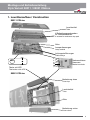
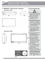
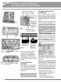
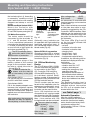
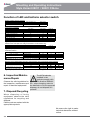
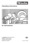
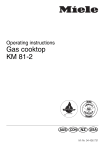
Montage- und Betriebsanleitung Mounting and Operating Instructions Style Variant 28011 CGLine Style Variant 28021 CGLine Zielgruppe: Elektrofachkraft Target group: Skilled electricians Montage und Betriebsanleitung Style Variant 28011 / 28021 CGLine Inhaltsverzeichnis Pos.Titel 1 Aufbau Maßbilder 2Sicherheitshinweise 3Normenkonformität/Verwendung 4 Technische Daten 5Installation 5.1 Montage 5.2 Netzanschluss 5.3 Leuchte komplettieren 5.4 Überwachung CGLine LED- u. Batteriewahlschalterfunktionen 6Wartung/Instandhaltung 7Recycling Seite 3 4 4 5 5 5 5 5 5 6 8 7 7 Contents: Pos.Titel 1Construction Dimensional drawings 2 Safety instructions 3 Conformity with standards 4 Technical data 5Installation 5.1 Assembly 5.2 Main connection 5.3 Complete luminaire 5.4 CGLine monitoring devices Function of LED a. batterie selector switch 6 Maintenance / Repair 7Recycling Page 3 4 8 8 8 8 8 8 9 9 10 10 10 2 Montage und Betriebsanleitung Style Variant 28011 / 28021 CGLine 1. Leuchtenaufbau / Construction 28011 CGLine Leuchtmittel Tube 4 Befestigungsschrauben für Gehäuseoberteil 4 screws for enclosure top part Akku Lampenfassungen Lamp socket Leitungseinführungen Cable entrys grün TEST green Taster mit LED L L L’ N PE Netzanschlussklemmen Mains terminals (nur Funktions-PE!) Test button with LED 28021 CGLine Abdeckung oben Cover top Leuchtmittel Tube Akku Abdeckung unten Cover down 3 Montage und Betriebsanleitung Style Variant 28011 / 28021 CGLine 1.1 Maßbilder / Dimensional drawings 2. Sicherheitshinweise Style Variant 28011 Die Leuchte ist bestimmungsgemäß in unbeschädigtem und einwandfreiem Zustand zu betreiben! Als Ersatz dürfen nur Originalteile von CEAG verwendet werden! Style Variant 28021 Bei Arbeiten an der Notleu- chte ist erst das Netz (La- dephase und L’) abzuschal- ten und dann der Batterie- kreis zu unterbrechen. Bild 2 zeigt das Hinweisschild auf der Notleuchte. Vor der ersten Inbetriebnahme muss die Leuchte entsprechend den im Abschnitt Installation genannten Anweisungen geprüft werden! Die Notleuchtenkennzeichnung vornehmen: Stromkreis, Leuchtennum- mer und ID-Nummer zu- ordnen und eintragen. Die manuelle Prüfbuch- führung ist nach den nationalen Vorschriften durchzuführen. Sie entfällt bei automatischer Prüf buchführung durch den CG-Controller! Alle Fremdkörper müssen vor der ersten Inbetriebnahme aus der Leuchte entfernt werden! Beachten Sie bei allen Arbeiten an der Leuchte die nationalen Sicherheits- und Unfallverhütungsvorschrif ten und die nachfolgenden Sicherheitshinweise in der Betriebsanleitung, die mit einem versehen sind! Bild 2 4 Montage und Betriebsanleitung Style Variant 28011 / 28021 CGLine 3. Normenkonformität Konform mit: EN 60 598-1, EN 60 598-2-22, EN 1838, Gemäß DIN EN ISO 9001 entwickelt, gefertigt und geprüft. 4. Technische Daten Eingangs230/240VAC spannung: 50 Hz Stromaufnahme: 70mA Leistungsauf16 VA(8W) nahme (AC): Lampe : 8W/T16 Nennlichtstrom der 8W-Lampe: 450 lm Lichtstrom 40%(PhiE/PhiNenn) am Ende der Nennbetriebsdauer Schutzklasse: II Schutzart nach EN 60527: IP 41 wahlweise: IP 54 Batterie: wiederaufladbar, war- tungsfrei, gasdicht Notlicht 1h: NC-Akku 3,6V,1,5Ah Notlicht 3h: NC-Akku 3,6V,4,0Ah zulässige Umgebungstemperatur bei Dauerlicht -5°C..+30°C bei Bereitschaftsli. 0°C..+35°C Netzanschlussklemmen: 3 x 2,5 mm² Busklemmen: 2 x 1,5 mm2 Gewichte: 28011-1/D: 1,7kg 28011-3/D: 1,9kg 28021-1/D: 1,6kg 28021-3/D: 1,8kg 4.2 Kurzbeschreibung / Verwendungsbereich Die Rettungs- und Sicherheitsleuchten STYLE Variant 28011 u. 28021 CGLine sind als Einzelbatterieleuchten in Installationen nach EN 50 172, DIN VDE 0100718 und DIN V VDE V 0108 -100 geeignet. Mit dem CEAG CG-Controller CGLine 400 und dem CGLine WEB-Interface können die Einzelbatterieleuchten über eine Busleitung zentral überwacht werden. 5.Installation/ Inbetriebnahme Halten Sie die für das Errichten und Betreiben von elektrischen Betriebsmitteln geltenden Sicherheitsvorschriften und das Gerätesicherheitsgesetz sowie die allgemein anerkannten Regeln der Technik ein! 5.1 Montage Style Variant 28011 Lösen Sie die Schnapphaken der Piktogrammscheibe mit einem geeignetem Schlitzschraubendreher (B. 3) und heben Sie die Piktogrammscheibe vom Gehäuse ab. Entfernen Sie das Leuchtmittel aus den Lampenfassungen. Lösen Sie die 4 Schrauben mit einem Kreuzschlitzschraubendreher und heben Sie das Gehäuseoberteil vom Gehäuseunterteil ab. Nach Installationsgegebenheit wahlweise vorgeprägte Leitungseinführungen seitlich oder an der Rückseite ausbrechen. Leitungseinführungsstopfen einsetzen und ein Loch für den verwendeten Leitungsdurchmesser einstanzen oder einschneiden. Bei Beschädigung der Dichtlippen ist die Leitungseinführung zum Erhalt der Schutzart zu ersetzen! Nicht benutzte, aber ausgebrochene Leitungseinführungen sind mit dem Leitungseinführungsstopfen zu verschließen (IP-Schutz). Die Leitungen sind in den Leuchtenkörper einzuführen und der Leuchtenkörper ist mit geeigneten Schrauben durch die 4 an den Gehäuseecken liegenden Löchern an Wand oder Decke zu befestigen (Bild 5). Style Variant 28021 Lösen Sie die Schnapphaken einer Piktogrammscheibe (wahlweise beide) mit einem geeignetem Schlitzschraubendreher (B.3) und heben Sie die Piktogrammscheibe vom Gehäuse ab. Entfernen Sie das Leuchtmittel aus den Lampenfassungen. Lösen Sie die Schnapphaken der trapezförmigen Abdeckung an der Einführungs- und Befestigungsseite der Leuchte (Bild 4). Nach Installationsgegebenheiten offene Leitungseinführung mit Leitungseinführungsstopfen verschließen und ein Loch einstanzen oder einschneiden. Details s. Style Variant 28011! Leuchte mit geeigneten Schrauben durch die angeformten Nocken an der Decke befestigen oder CEAGZubehörteile verwenden (Bild 6). 5.2 Netzanschluss Das Netzkabel ist an den Klemmen N, L, L’ sowie an PE anzuschließen, wobei L als ungeschaltete Dauerversorgung der Elektronik und L‘ über einen Lichtschalter zur bedarfsabhängigen Schaltung der Lampe dient (B.7). Der PE-Anschluss dient als Funktionserde. Er hat keine Schutzfunktion! 5.3 Leuchte komplettieren Die Fastonstecker der Akkuleitungen auf die Kontaktstecker auf der Leiterkarte aufstecken - rote Leitung an +(Plus) , blaue Leitung an -(Minus). (Bild 9). Für die Nachvollziehbarkeit der Batterie-Lebensdauer bitte das Inbetriebnahme-Datum in das auf der Batterie vorgesehene Feld eintragen! Leuchmittel in die Fassungen stecken. Style Variant 28011: Gehäuseoberteil aufsetzen und mit den 4 Schrauben fixieren. Style Variant 28021: Trapezförmige Abdeckung zwischen den angeformten trapezförmigen Blöcken des Gehäuses einlegen und die 4 Schnapphaken einrasten. Die Piktogrammscheibe(n) auf das Leuchtengehäuse aufschnappen. 5 Montage und Betriebsanleitung Style Variant 28011 / 28021 CGLine Batteriewahlschalter S2 Battery selector switch S2 5.5 Überwachungseinrichtung CGLine D i e L e u c h t e n S t y l e Va r i a n t 28011/28021 CGLine sind für CGLine-Busanden Anschluss an den CEAG CGschluss Bus connection Controller CGLine 400 oder das CGLine WEB-Interface vorbereitet (B. 7). + Taster/LED- Jeder Leuchte der Leuchtenserie CGLine ist eine individuelle, unAnschluss Button/LED verwechselbare Identifikationsconnection nummer mit 6 Ziffern zugeordnet. Markierung Diese ID-Nummer muss für späMarker tere Konfigurationsarbeiten in Bild 7 den Installationsplan übertragen Fig. 7 Batterieanschluss werden. Battery connection Dazu dient der abziehbare IDAufkleber in der Leuchte. An eine 2-adrige Busleitung können bis zu 100 Leuchten angeschlossen und mit dem CGController CGLine / CGLine WEBInterface verbunden werden. Max. 4 Busleitungen mit je 100 Leuchten können so überwacht werden. Die max. Datenleitungslängeschaltetes Bereitschaftsge beträgt je Strang bei licht ohne, Dauerlicht Dauerlicht mit 0,5 mm2 - 450m Bild 8 Brücke zwi1,0 mm2 - 900m Fig. 8 schen L u. L’ 1,5 mm2 - 1300m Daten je Strang: Busspannung: 22,5VDC Jede Leuchte kann wahlweiMax.Spg.-Abfall: 13VDC se mit bedarfsabhängiger Busstrom: 400mA Lichtschaltung (geschaltetes Als Datenleitung kann eine unDauerlicht), in Bereitschaftsgeschirmte, 2-adrige Leitung in lichtschaltung sowie in Dauerfreier Bus-Topologie zum Einsatz lichtschaltung betrieben werden kommen. (Bild 8). Jede an der Daten-Bus-Leitung angeschlossene Leuchte wird vom Taster/LED-FolienCG-Controller / WEB-Interface Anschluss automatisch erkannt. Es kann den angeschlossenen Leuchten eine Beim Wechsel von Taster/LED Kurzadresse zugewiesen werden, oder Leiterkarte bitte Markiedie über die drei LEDs an der rung 1 auf der Leiterkarte und Leuchte abgefragt werden kann. auf der Leiterbahnfolie beachten! (Bild 7) Mit den drei LEDs an der Aus Off Ein (1h/3h) On Bild 3 Fig. 3 Bild 4 Fig. 4 Bild 5 Befestigungslöcher 28011 Fig. 5 Bild 6 Fig. 6 Fixing holes Befestigungslöcher 28021 Fixing holes 1 _ Nach Netzwiederkehr läuft das Notlicht noch ca. eine Minute nach (nachlaufendes Notlicht)! 6 Leuchte werden nachstehende Statusanzeigen angezeigt: - keine Störung - Leuchte im Funktionstest - Leuchte im Betriebsdauertest Montage und Betriebsanleitung Style Variant 28011 / 28021 CGLine - Ladestörung - Funktionstest - Störung - Betriebsdauertest - Störung - Leuchtmittel defektZusätzlich können mit der Test-Taste gestartet und angezeigt werden: - Funktionstest EIN - Betriebsdauertest EIN / AUS - Betriebsdauertest verzögert - Einstellung der Notlichtbetriebszeit mit anschließender Identifikation der Leuchtenkurzadresse (bei angeschlossenem Datenbus sowie vergebener Kurzadresse durch den CGController). Der verzögerte Betriebsdauertest wird angezeigt, wenn die Leuchte nicht ununterbrochen 24 h geladen oder wenn innerhalb der 24 h schon ein Betriebsdauertest gestartet wurde. siehe Tabelle 1 Seite 8 Autarker Betrieb Nach der Erstinstallation / Netzanschluss wird wöchentlich ein automatischer Funktionstest sowie alle 3 Monate ein Betriebsdauertest auch ohne CGController CGLine/ CGLine WEBInterface gestartet. 6. Inspektion/War- tung/Instandhaltung Halten Sie die für die Inspektion, Wartung und Instandhaltung von elektrischen Betriebsmitteln geltenden Bestimmungen ein! 7. Entsorgung / Recycling Beachten Sie bei der Entsorgung defekter Geräte die gültigen Vorschriften für Recycling und Entsorgung. Kunststoffteile sind mit entsprechenden Symbolen gekennzeichnet. Der in der Leuchte eingebaute NiCd-Akkus ist - entsprechend der EU-Richtline 2006/66/ EG - beim Wechsel an den Vertreiber oder an einen zugelassenen Entsorger zurückzugeben und darf nicht selbst entsorgt werden! LED- und Batteriewahlschalterfunktionen Einstellung des Schalters S2: Stellung On Off Notlichtnennbrenndauer 3h 1h Batt. Kapazität 4 Ah 1,5 Ah Kodierung der Fehleranzeige: Status LED Grün LED Gelb Keine Störung � � Notlicht � � Nachlaufendes Notlicht � im Wechsel ca. 1 Min. � Leuchte im Funktionstest (FT) � � Leuchte im Betriebsdauertest (BT) � � Ladestörung � � Funktiontest-Störung � � Betriebsdauertest-Störung � � Leuchtmittel-Störung � � � =LED leuchtet; � =LED leuchtet nicht; � =LED blinkt; � =LED blitzt; LED Rot � � � � � � � � � Anzeige Blockiermodus (nur mit vorhandenem Netz und Aktivierung vom CG Controller): Status LED Grün Blockiermodus � � =LED leuchtet; � =LED leuchtet nicht; � =LED blinkt; LED Gelb � LED Rot � Funktions- und Betriebsdauertest: Prüftaster betätigen für 1 Sek. < t < 5 Sek. Funktion LED Grün Funktionstest Ein � Betriebsdauertest Ein/Aus � Betriebsdauertest ist verzögert � � ( 1s ) Reset der Leuchte t > 10 Sek. � =LED leuchtet (für 1s); � =LED leuchtet nicht; � =LED blinkt; � =LED blitzt t > 5 Sek. LED Gelb � � � � (1s) LED Rot � � � (1s) � (1s) LED Gelb � � � Zehner Stelle 10-90 LED Rot � � � Einer Stelle 1 - 9 Abfrage der eingestellten Batteriebestückung / Notlichtbrenndauer / Leuchtenadresse Prüftaster betätigen für LED Grün � � automatisch nach 2 Sek. bei angeschl. � Hunderter Leuchtenadresse Controller CGLine 400 Stelle 100-400 � =LED leuchtet; � =LED leuchtet nicht; � =LED blinkt (Anzahl der Stellen) t<1 Sek. Notlichtbetriebszeit 1h 3h Technische Änderungen vorbehalten! 7 Mounting and Operating Instructions Style Variant 28011 / 28021 CGLine 2. Safety Instructions The device shall only be used for its intended purpose and in undamaged and perfect condition! 3. Conformity with Standards Conforms to: EN 60 598-1, EN 60 598-2-22, EN 1838, DIN. Developed, manufactured and tested in accordance with DIN EN ISO 9001. 4. Technical data Only genuine CEAG spare parts may be used for re- Input voltage: 230/240 V AC 50 Hz placement and repair! Rated current 70 mA When working on the emer- (AC): gency luminaire first cut off Power conmains (charging phase and L’) sumption (AC): max. 16 VA 8 W/T16 and interrupt battery operati- Lamp: Rated lumion. Fig. 9 shows the indication nous flux of label on the emergency luminthe lamp: 450 lm aire. Rated lumi Prior to its initial operation, nous flux: 40% (phiE/phinominate) the luminaire will have to be at the end of operating cycle Insulation checked in accordance with class: II the instructions as per section Protection category acc. Installation! to EN 60529: IP 41 Carry out the marking of the At option: IP 54 gas-tight,reloadable, emergency luminaire: Assign Accu: maintenance-free the circuit, the luminaire No. Rated operating cycle: and ID-No. and enter them. 1h: NC-accu 3.6V, 1.5Ah 3h: NC-accu 3.6V, 4.0Ah The manual log book shall be performed in compliance with Admissible ambient the national regulations. It is temperature maintained light: - 5°C...+35°C not applicable by automatical non maintained light: log book with the CG-Con 0°C...+30°C troller CGLine! Supply 3 x 2.5 mm² Any foreign matter shall be terminals: 2 removed from the luminaire Bus terminals: 2 x 1.5 mm Weight: 28011-1/D 1.7kg prior to its initial operation! 28011-3/D 1.9kg 28021-1/D 1.6kg Observe the national safe28021-3/D 1.8kg ty rules and regulations for prevention of accidents as 4.2 Brief Description/Area well as the safety instructions of Application included in these operating As a self-contained luminaire instruction marked with the STYLE Variant 28011/28021 CGLine emergency and safety luminaire is suitable for installations according to EN 50 Fig. 9 172, DIN VDE 0100-718 and 8 DIN V VDE V 0108-100. With the CEAG CG-Controller CGLine 400 or the CGLine WEB-Interface the selfcontained luminaires can be monitored centrally via a bus cable. 5. Installation For the mounting and operation of electrical apparatus, the respec-tive national safety regulations as well as the general rules of engineering will have to be observed. 5.1 Assembly Style Variant 28011 Loose the snap hooks of the legend cover with a qualified slotheaded screwdriver (pict. 3) and lift the cover from the enclosure. Remove the lamp from the socket. Loose the 4 screws with a crossslotted screwdriver and lift the top part of enclosure from the lower part. According to assembly conditions tweak out optional the impressed cable entries sideways or on the backside. Enter the sealing stopper and stamp or cut out a hole for the using cable diameter. If the sealing lips are damaged, replace the cable entries to maintain the protection. Unused cable entries which are tweaked out must be closed with sealing stoppers (IP - degree of protection). Insert the cable in the body of the lamp and attach it through the 4 holes in the corners of enclosure to the wall or ceiling with appropriate screws (pict. 5). Style Variant 28021 Loose the snap hooks of the legend cover with a qualified slot-headed screwdriver (pict. 3) and lift the cover from the enclosure. Remove the lamp from the socket. Loose the snap hooks of the trapeze shaped cover at the entries- and mounting-side of Mounting and Operating Instructions Style Variant 28011 / 28021 CGLine the luminaire (pict. 4). According to assembly conditions close open cable entries with sealing stoppers and stamp or cut out a hole. Details see Style Variant 28011! Mount the luminaire with appropriate screws to the ceiling or use CEAG spare parts (pict. 6). 5.2 Mains Connection The mains cable should be connected to the terminals N, L, L’ and PE terminal, where L is an unswitched permanent connection for the electronics and L’ is used for switching the lamp on and off with a light switch as and when required (Fig. 7). The PE-connection serve as function earth. It has no function of protection. 5.3 Complete Luminaire Plug the faston plugs of the battery cables to the contact plugs on the conductor board red wire to +(plus), blue wire to - (minus) (Fig. 9). To fathom batteries life please note the start-up date on the battery in the given data field. Style Variant 28011: Put up the top part of enclosure and fix it with the 4 screws. Style Variant 28021: Put in the trapeze shaped cover between the adjusted trapeze shaped blocks of enclosure and snap the 4 snap hooks. Snap the legend cover on the enclosure of the luminaire. After mains return the emergency operation will stay for approx. 1 minute (delay on mains return)! switched maintained light Fig. 10 non maintained light without -maintained light with jumper L and L’ Optionally, every luminaire can be operated with light switching (switched maintained light), in non maintained mode or in maintained mode (Fig.10). Button/LED-foil-connection Changing button/LED or printed circuit please see marker 1 on the printed circuit and on the printed conductor (Fig. 9). 5.4 CGLine Monitoring Device The STYLE Variant 58011/58021 CGLine luminaires are prepared for connection to the CEAG CG- Controller CGLine 400 or CGLine WEB-Interface (Fig. 7). An individual, distinct identification number (6 characters) is assigned to every luminaire in the CGLine luminaire series. This ID number must be transferred to the installation plan for subsequent configuration work. The removable ID sticker in the luminaire can be used for this. Up to 100 luminaires can be connected to a 2-core bus cable and linked to the CG-Controller CGLine / CGLine WEB-Interface. Max. 4 bus cables with 100 luminaires each can be monitored. The max. data line length per strand is 2 0.5 mm - 450m 2 1.0 mm - 900m 2 1.5 mm - 1300m Data per strand: Bus voltage: 22.5VDC Max. voltage drop: 13VDC Bus current: 400mA An unscreened, 2-core cable with free bus topology can be used as a data cable. Each of the luminaires connected to the data bus cable is automatically recognised by the CGController / WEB-Interface. Short address can be assigned to the connected luminaires, which can be polled via the three LEDs on the luminaire. The three LEDs (Fig.6 and 8) on the luminaire indicate the following status: - no fault - luminaire in function test - luminaire in duration test - charging fault - function test - fault - duration test - fault - luminescent material faulty In addition, the following can be started and displayed with the test button: - function test ON - duration test ON / OFF - duration test delayed - setting the emergency light operating time with subsequent identification of the luminaire short address (when data bus is connected and a short address has been assigned). The delayed duration test is displayed if the luminaire is not charged without interruption for 24 h or if an duration test is started within the 24 h. see Table 2 page 11 Autarchic Operation After the initial installation / mains connection the luminaire starts the function test weekly and a duration test every three months also without the CG-Controller CGLine / CGLine WEB-Interface. 9 Mounting and Operating Instructions Style Variant 28011 / 28021 CGLine Function of LED and batterie selector switch Position of battery selector switch S2 Position On Off Rated operating cycle 3h 1h Batt. capacty 4 Ah 1,5 Ah Coding of the fault display: Status LED green LED yellow No failure � � Emergency mode � � � alternately 1 min. � Delay-time on mains return Luminaire in function test � � Luminaire in duration test � � Charging fault � � Fault in function test � � Fault in duration test � � Fault with luminescent material � � � =LED lights up; � =LED does not light up; � =LED blinks; � =LED flashes; LED red � � � � � � � � � Indication block mode (with main voltage and activation of CG-Controller only) Status LED green Block mode � � =LED lights up; � =LED does not light up; � =LED flashes; LED yellow � LED red � Test button funktions Test button pressed for: 1 sec. < t < 5 sec. Function LED green LED yellow Function test On � � Duration test On / Off � � t > 5 sec. Duration test delayed � � � ( 1s ) � (1s) Reset of the luminaire t > 10 sec. � =LED lights up (für 1s); � =LED does not light up; � =LED blinks; � =LED flashes LED red � � � (1s) � (1s) Monitoring of the adjusted battery mounting / rated operating cycle and the address of the luminaires Test button pressed for: LED green � � automatically after 2 sec.with � Hundred Address of the luminares connected CG-Controller CGLine digit 100-400 � =LED lights up; � =LED does not light up; � =LED blinks (Number of digits) t<1 sec. Emergency operating time 1h 3h LED yellow � � � Ten digit 10-90 LED red � � � One digit 1-9 6. Inspection/Maintenance/Repair The NiCd batteries installed in the luminaire comply with EU directive 2006/66/ Observe the valid regulations for the inspection, maintenance and EG - when changing, return to repair of electrical equipment! the distributor or to an approved disposer; do not dispose of it yourself! 7. Disposal/Recycling When disposing of faulty equipment, observe the valid regulations for recycling and disposal. Plastic parts are marked with the appropriate symbols. We reserve the right to make technical alterations without notice. 10 Mounting and Operating Instructions Style Variant 28011 / 28021 CGLine 11 CEAG Notlichtsysteme GmbH Senator-Schwartz-Ring 26 59494 Soest Germany Tel: Fax: Web: Email: +49 (0) 2921/69-870 +49 (0) 2921/69-617 www.ceag.de [email protected] 400 71 350 081 (E)/XXX/02.12/WK Cooper Safety Jephson Court Tancred Close Royal Leamington Spa Warwickshire CV31 3RZ United Kingdom Tel: Fax: Web: Email: +44 (0) 1926 439200 +44 (0) 1926 439240 www.cooper-safety.com [email protected]