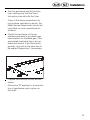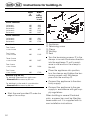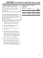
1
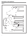
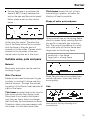
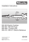
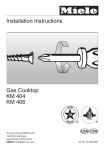
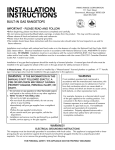
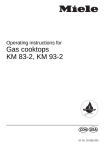
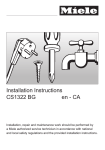
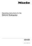
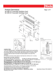
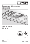
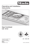
Operating instructions
Gas cooktop
KM 81-2
CANADIAN GAS ASSOCIATION
R
APROVED
@]äö
M.-Nr. 04 426 731
Description of the appliance
Description of the appliance
KM 81-2
2
Description of the appliance
Description of the appliance
KM 81-2
b Trivet
c Wok/pan support
d Small burner cap
e Large burner cap
f Burner ring
g Large burner cap base
h Ignitor
i Cable for connection
to electrical supply approx. 3.6 ft
(1.10 m) long.
j Ignition safety control
k Burner base
l Control for burner
m Control panel
Data plate
Because the data plate is no longer
visible once the appliance has been
built in, a 2nd data plate is supplied
which should be placed into the space
provided on page 16 of these instructions under After Sales Service.
Special accessories
Special accessories are available from
your Miele Dealer or from the Spare
Parts Department.
Stainless steel cover-EA 80
A stainless steel cover is available for
the KM 81-2 cooktop. Check availability in each country.
For installation of the cover, a minimum
distance of 20" (510 mm) is required between the countertop and wall cabinetry.
Note:
The wok/pan support should be
removed before lowering the stainless
steel cover (EA 80).
Do not install the Da 8-2 directly
next to the gas hob.
3
Contents
Contents
Description of the appliance . . . . . . . . . . . . . . . . . . . . . . . . . . . . . . . . . . . . . . . . . 2
For your safety . . . . . . . . . . . . . . . . . . . . . . . . . . . . . . . . . . . . . . . . . . . . . . . . . . . . 5
Help protect our environment . . . . . . . . . . . . . . . . . . . . . . . . . . . . . . . . . . . . . . . . 6
Warning and Safety Instructions . . . . . . . . . . . . . . . . . . . . . . . . . . . . . . . . . . . . . 7
Burner
Burner control . . . . . . . . . . . . . . . . . . . . . . . . . . . . . . . . . . . . . . . . . . . . . . . . . . . .
Instructions for using the gas burner . . . . . . . . . . . . . . . . . . . . . . . . . . . . . . . . . . .
Power cut . . . . . . . . . . . . . . . . . . . . . . . . . . . . . . . . . . . . . . . . . . . . . . . . . . . . . . . .
Suitable woks, pots and pans . . . . . . . . . . . . . . . . . . . . . . . . . . . . . . . . . . . . . . . .
11
11
12
13
Cleaning and care . . . . . . . . . . . . . . . . . . . . . . . . . . . . . . . . . . . . . . . . . . . . . . . . 14
Problem solving guide. . . . . . . . . . . . . . . . . . . . . . . . . . . . . . . . . . . . . . . . . . . . . 16
After Sales Service. . . . . . . . . . . . . . . . . . . . . . . . . . . . . . . . . . . . . . . . . . . . . . . . 17
For the installer / electrician / engineer
]ö Electrical connection . . . . . . . . . . . . . . . . . . . . . . . . . . . . . . . . . . . . . . . 18
@ä Electrical connection . . . . . . . . . . . . . . . . . . . . . . . . . . . . . . . . . . . . . . . 19
]ö Gas connection . . . . . . . . . . . . . . . . . . . . . . . . . . . . . . . . . . . . . . . . . . . 20
@ä Gas connection . . . . . . . . . . . . . . . . . . . . . . . . . . . . . . . . . . . . . . . . . . . 22
Appliance dimensions . . . . . . . . . . . . . . . . . . . . . . . . . . . . . . . . . . . . . . . . . . . . . 23
]ö Instructions for building-in. . . . . . . . . . . . . . . . . . . . . . . . . . . . . . . . . . . 25
@ä Clearance above and around the appliance. . . . . . . . . . . . . . . . . . . . . 28
@ä Installation . . . . . . . . . . . . . . . . . . . . . . . . . . . . . . . . . . . . . . . . . . . . . . . 30
@ä Instructions for building-in . . . . . . . . . . . . . . . . . . . . . . . . . . . . . . . . . . . 32
]ö Conversion to alternative types of gas . . . . . . . . . . . . . . . . . . . . . . . . . 33
@ä Conversion to alternative types of gas . . . . . . . . . . . . . . . . . . . . . . . . . 37
For your safety
For your safety
WARNING: If the information in
this manual is not followed
exactly, a fire or explosion may
result causing property damage,
personal injury or death.
Do not store or use gasoline or other
flammable vapors and liquids in the
vicinity of this or any other appliance.
WHAT TO DO IF YOU SMELL GAS
– Do not try to light any appliance.
– Do not touch any electrical
switch; do not use any phone in
your building.
– Immediately call your gas supplier from a neighbor’s phone.
Follow the gas supplier’s instructions.
– If you cannot reach your gas supplier, call the fire department.
Installation and service must be
performed by a qualified installer,
service agency or the gas supplier.
Note to the installer (CDN and USA)
LEAVE THESE INSTRUCTIONS
WITH THE CONSUMER.
The appliance and its individual shutoff
valve must be disconnected from the gas
supply piping system during any pressure
testing of that system at test pressures in
excess of 1/2 psi (3.5 kPa).
The appliance must be isolated from the
gas supply piping system by closing its
individual manual shutoff valve during
any pressure testing of the gas supply
piping system at test pressures equal to
or less than 1/2 psi (3.5 kPa).
For Canada only:
The minimum supply pressure for
checking the regulator setting shall be
5 inches water column (1246 Pa),
which is 1 inch water column (249 Pa)
above the manifold pressure of 4 inches water column (996 Pa).
Instructions for replacement of fixed orifices are shown on page 32. Save the
orifices removed from the appliance for
future use.
5
Help protect our environment
Help protect our environment
Disposal of packaging
The transport and protective packing is
mostly manufactured from the following
re-usable materials:
– Corrugated paper / card board mostly from recycled materials.
– Polyethylene foil (PE) - partly from
secondary raw materials.
Rather than just throwing these materials away, please take them to the
nearest local authority collection point
for specific waste.
Disposal of your old machine
Old machines contain materials which
can be recycled. Please contact your
local authorities or scrap merchant
about potential recycling schemes, before disposing of the appliance.
Read the notes on page 9 before disposing of the appliance.
6
Warning and Safety Instructions
Warning and Safety Instructions
Important safety instructions
Warning:
When using your cooktop unit,
follow basic safety precautions
including the following:
This appliance complies with all relevant legal safety requirements. Improper use of the appliance can,
however, present a risk of both personal injury and material damage.
Before installating and using the appliance for the first time, read the
operating instructions carefully.
They give information on safety, on
the operation and care of the appliance. This way you will avoid the
risk of accidents and damage to the
appliance.
This appliance is intended for domestic use.
Should it be installed for commercial
use, the relevant regulations must be
observed.
Do not use the unit unless all parts
are properly in place according to the
installation and operating instructions.
Ensure that the gas pipe and electrical cable are installed in such a
way that they do not touch any parts of
the appliance which become hot. This
could cause damage.
The electrical safety of this appliance can only be guaranteed
when continuity is complete between
the appliance and an effective earthing
system.
It is imperative that this basic safety requirement be tested and where there is
any doubt, the electrical system of the
house should be checked out by a
qualified electrician. The manufacturer
cannot be held responsible for damage
caused by the lack or inadequacy of
an effective earthing system.
Installation work and repairs may
only be carried out by a suitably
qualified and competent person.
Repairs and other work by unqualified
persons could be dangerous.
Do not connect the appliance to the
mains electrical supply by an extension cord. Extension cords do not guarantee the required safety of the appliance.
Gas burners should only be used
in rooms with adequate ventilation.
Ensure that the bench top area around
the cooktop is clear of obstacles to
allow sufficient ventilation.
The appliance is only completely
isolated from the elecrical supply
when it is switched off at the wall
socket, or the mains fuse is withdrawn.
Do not pull by the mains cable, but by
the plug when withdrawing the plug
from the socket.
Important notes for the installer
Please ensure that the domestic
electrical supply corresponds to
the information on the data plate.
You should find out details about the
type of gas and calorific value from
your Gas Board and compare this information with the type of gas quoted on
the data plate.
They must correspond.
7
Warning and Safety Instructions
Warning and Safety Instructions
Check that all the burners are correctly assembled before igniting
the gas, otherwise the ignition could
malfunction.
Please note the following, in case
unit is on LPG supply:
Where this appliance is installed in
marine craft or in caravans, it shall
not be used as a space heater.
Wall sealing strips must be heatresistant and any backmoulding
must be of heat resistant material.
The minimum clearances (USA/CDN):
from adjacent combustible construction – 10" (250 mm),
between appliance and rear wall or
front of backsplash – 90 mm (CDN)
or 3 1/2" (USA),
between appliance and overhead
combustible construction
– 30" (760 mm) or
65 cm (26") between the cooktop
and a cooker hood above it,
between appliance and front edge of
countertop – 2 1/4" (55 mm),
depth of overhead cabinets must not
exceed – 13" (330 mm),
between combustible constructions
and the extending cooking surface
– 460 mm (Canada).
8
The minimum clearances (AUS/NZ):
When installing the gas cooktop,
the following minimum dimensions
must be kept.:
See "Clearance above and around
the appliance" (pages 27 – 31),
60 cm between the cooktop and a
cooker hood above it.
Leave these instructions with the
consumer.
Important notes for the user
For safety reasons, this cooktop
should only be installed as a builtin appliance.
Do not let small children use the
appliance or touch it during operation. Not only do the cooking areas
heat up, but also the control panel.
Danger of burning. Keep all pans out of
the reach of children. Supervise use of
the cooktop by the elderly or infirm.
Warning and Safety Instructions
Warning and Safety Instructions
When cooking or boiling in large
pots or pans, ensure that there is a
minimum distance of 2" (50 mm) between the pot and a heat-sensitive
countertop. After combustion, the hot
gases flow outwards under the base of
the pot and may consequently burn the
edge of the countertop if it is too close.
Make sure that there is a minimum
distance of 5/8" (15 mm) between
the pot or pan and the control panel.
Never place a pot on the control panel.
When using an electrical plug near
the cooktop, care should be taken
to ensure that the cable of the electrical
appliance does not fall into the flames.
Note that potential hazards may
exist with overhead cabinets.
The wok/pan support and trivet (if
supplied) heat up when the burners are in use. Do not touch them until
they have cooled down. The use of
oven gloves is recommended.
Do not let cooking grease or other
flammable materials accumulate
on the unit.
Never leave the unit unattended
when cooking with oil or fat. Very
hot oil can cause a fire.
Allow sufficient time for the unit to
cool before touching or exposing
surface areas to flammable materials.
Always ensure that food is sufficiently cooked or reheated.
Many factors will affect the overall cooking time, including the size and amount
of food, its temperature, changes to the
recipe and the shape and size of cooking container.
Some foods may contain microorganisms which are only destroyed by
thorough cooking, therefore when cooking or reheating foods, e.g. poultry, select a longer cooking or reheating time.
It is essential to ensure that food
has been evenly and sufficiently
heated. To check that it is thoroughly
cooked, turn or stir during cooking if
necessary.
If high settings are used, remain
near the cooktop in case grease
should splatter or liquids boil over,
which may cause smoking.
Never use damp potholders.
Use only suitable cookware for
range-top service. Unsuitable
cookware may break due to a sudden
temperature change.
Avoid allowing liquids or foods containing salt to spill on to a stainless
steel cooktop. Should this happen,
wipe up any spillages containing salt
immediately, otherwise discoloration
could occur.
Do not use the control panel as a
resting place for pots and pans.
9
Warning and Safety Instructions
Warning and Safety instructions
When using a cooker hood over
the gas cooktop, ensure that any
burners in use are always covered with
a pan.
Otherwise flames could be drawn up
by the suction of the cooker hood,
parts of which could then be damaged.
Fat residues in the filter could catch fire.
Do not use the gas cooktop to heat
up the room. The high temperatures of the cooktop could cause inflammable objects in the vicinity to
burn.
Spray canisters, aerosols or inflammable substances must not be
stored in the drawer beneath the cooktop. Any cutlery trays must be made of
a heat resistant material.
Before removing pots and pans,
be sure to turn the surface unit to
“OFF”.
Always heat fat slowly, watching as
it heats.
When frying foods, make sure that
the food is as dry as possible so
as to prevent moisture from causing hot
fat to bubble over.
When shallow or deep frying, do
not overfill the pan with oil.
Do not use spray aerosols in the
vicinity of the appliance while it is
in operation.
Under no circumstance use a
steam-cleaning appliance to clean
the gas cooktop.
The steam could penetrate to live components and cause a short circuit.
10
In countries which may be subject
to infestation by cockroaches or
other vermin, pay particular attention to
keeping the appliance and its surroundings in a clean condition at all times.
Any damage which might be caused
by cockroaches or other vermin will not
be covered by the appliance guarantee/warranty.
SAVE THE INSTRUCTIONS!
Keep these instructions in a safe
place and pass them on to any future
user.
Disposal of discarded appliances
Before disposing of an old appliance, ensure that disconnection
from the gas supply is made by a suitably competent person. Switch off at
the mains, disconnect and remove the
appliance cable at both ends and render useless. This is intended to prevent
the discarded appliance from being a
hazard.
The manufacturer cannot be held
liable for damage caused by noncompliance with safety instructions.
Burner
Burner
Before using for the first time, take
heed of the “Warning and Safety
Instructions”.
Burner control
The inner and outer burner are both
controlled by one knob.
The burner control knob may only
be turned counter-clockwise and
back in a clockwise direction. Otherwise the control could be damaged.
/ Simmer setting (inner ring on low,
outer ring off)
The gas flame is lit by electrical ignition.
When the burner control is pressed in the
strong flame position, a spark passes from
the electrode to the burner and ignites the
gas to give a flame (see page 11).
The burner is equipped with an ignition
safety device. If a gas flame goes out, for
example, if food boiled over, or if there
was a sudden draft, the ignition safety
control cuts off the supply of gas in a
maximum of 90 seconds.
Instructions for using the gas
burner
The flame strength can be selected:
X Gas switched off
&
Strong flame (outer and inner rings
both produce high flames)
& Low flame (outer ring on low,
inner ring on high)
& Intermediate state b (provides
ignition for outer ring from inner ring)
/ Very low flame (inner ring on high,
outer ring off)
Place the wok or the pan on the
wok/pan support.
A trivet is supplied with the gas cooktop. It is designed to sit on the wok/
pan support when using small pans.
The trivet should only be used on the
burner with a simmer setting. It should
only be used with pans with a diameter
of less than 4" (10 cm).
11
Burner
Burner
Press in the control knob and turn
counter-clockwise to the high setting
(largest flame symbol).
When the flame ignites, keep the
button pressed in for 5-10 seconds,
and then press down once more
firmly before letting go.
If the flame goes out, repeat the procedure, keeping the control knob pressed
in for a few extra seconds.
To turn the heat down from the
highest to the lowest setting, turn the
control counter-clockwise until it
stops (low flame position), press and
continue to turn the control to the
desired setting.
To turn the heat up from the lowest to
the highest setting, turn the control
clockwise until it stops (intermediate
stage & b), press and continue to
turn clockwise to the high setting.
To switch the burner off, turn the control knob in a clockwise direction to
the “l“ position. The flame will go out.
Power cut
If there is an interruption to the electrical supply, the gas can be ignited with
a match.
Light a match, press in the burner control and turn counter-clockwise to the
highest setting (large flame).
With the control knob pressed in, ignite
the gas at the burner with a match.
If, after several attempts the gas still
does not burn, check whether the lug
of the large burner cap is correctly positioned in the notch in the large burner
cap base and whether the lug of the
large burner cap base is correctly positioned in the notch in the burner base.
Turn the control knob to the highest
setting for boiling or searing food,
the lower setting for continuing cooking and for keeping food warm.
Turn the control knob down to a lower
setting in good time in order to prevent
food from boiling over or burning.
12
Keep the control knob pressed in for
a further 5-10 seconds, and then
press firmly down once again before
letting go.
Important:
Only woks/pans with a max.
diameter of 280 mm (11") should be
used on the gas cooktop.
If woks/pans have a larger
diameter, the flame may spread out
to the sides of the wok or the pan
and damage or burn the countertop
or surrounding units.
Burner
Burner
Ensure that there is a minimum distance of 5/8" (15 mm) between the
wok or the pan and the control panel.
Never place a pan on the control
panel.
The outer part of the gas flame is much
hotter than the center. Therefore the
tips of the flame should be in contact
with the base of the pan and not
spread out to the sides. Flames which
spread out to the sides of the pan
merely warm up the air in the room.
Thick bases lessen the risk of food
overheating in places, as better distribution of heat is possible.
Shape of woks, pots and pans
Using a small one on the strong flame
does not mean faster cooking but simply results in wasteful gas consumption. The correct procedure is to cook
with small pots on the low flame and
large ones on the strong flame.
small pots = low flame
large pots = strong flame
Suitable woks, pots and pans
Material
Most woks and pans can be used for
cooking on gas.
Wok / Pan base
Bases do not need to be even for gas
cooking, in contrast to those used on
electric burners. Through the spreading action of the flame, heat reaches all
parts of the base.
Thin bases conduct heat to the food inside more quickly than thicker ones.
Since heat is not evenly distributed
over the pan base, there is a danger
that food may be overheated in places.
Therefore, when using saucepans with
thin bases, stir the food more often.
Wide, flat pots are more suitable than
narrow, tall ones, since they heat up
more quickly.
Lids
Less heat is lost by cooking in a
covered pot.
13
Cleaning and care
Cleaning and care
In the event of a pan boiling over, clean
the burner and the cooktop surface immediately, to prevent the boiled over
substance from burning on.
Burner
The burner can be dismantled for
cleaning when cold.
Burner caps
The burner caps can be cleaned with a
solution of dishwashing liquid.
Do not use any caustic cleaners,
scouring powders, knives or hard
brushes, as these will cause scratches.
With time and use, the surface of the
burner caps will become dull.
Electronic ignition
The ignition device electrodes on
the burner must always be dry,
otherwise they will not spark.
From time to time, the electrodes
should be wiped with a well wrung-out
cloth and wiped dry with a clean cloth.
Important: Do not damage the ignition electrodes and the thermo
element.
14
Important: The burner must be correctly fitted together before it is lit,
otherwise the ignition device could
be damaged.
When fitting the large burner cap base
to the burner base, ensure that the locating lug fits exactly into the appropriate notch.
Place the burner ring onto the large burner cap base.
Place the large burner cap onto the
large burner cap base, ensuring that
the locating lug fits exactly into the appropriate notch.
Cleaning and care
Cleaning and care
Wok/pan support, trivet
Caution: the wok/pan support and
trivet become hot in use.
The wok/pan support and trivet can be
removed for cleaning.
The wok/pan support and trivet can be
cleaned in a hot solution of dishwashing liquid.
Never use scouring agents as these
could scratch the surface.
Dry with a cloth.
Do not use any scouring agents or
pads, knives or hard brushes.
These will cause scratching.
Do not use cleaning agents containing acids. A proprietary cleaning
agent for stainless steel can be
used on the stainless steel cooktop
surface.
Control panel / Control knob
Do not use any scouring agents or
pads on the knob or control panel,
as these could cause damage.
Cooktop surface
Avoid allowing liquids or foods containing salt to spill on to the stainless steel cooktop. Should this happen, wipe up any spillages
immediately.
Otherwise discoloration could occur.
Remove dust, oils and fats, spillages of
foods and condensed water from pots
and pans immediately to prevent it from
drying on. Dried on food residues are
easier to remove if they are first softened with warm water.
Clean the cooktop surface using hot
water with a little dishwashing liquid.
Clean the control knob and the control
panel with hot water and a little dishwashing liquid.
After application, rub dry with a clean
cloth.
Under no circumstances use a
steam-cleaning appliance to clean
the gas cooktop. The steam could
penetrate to live components and
cause a short circuit.
15
Problem solving guide
Problem solving guide
Repairs to the gas and electrical
components of this appliance must
only be carried out by a suitably
qualified person. Repairs by unauthorized personnel could be dangerous.
However some minor problems can be
resolved as follows:
What to do if . . .
. . . the burner does not ignite after
several attempts?
Check whether:
the large burner cap and the large
burner cap base are correctly positioned.
the gas supply valve is turned on.
a main fuse has blown. In this case
call an electrician or the Miele Service Dept.
Use a match to light the gas (see
page 11).
. . . the shape and color of the flame
are different from usual?
Check whether the burner caps and
large burner cap base are correctly
positioned.
16
. . . the gas flame goes out after
being lit?
Check whether the large burner cap
and the large burner cap base are
correctly positioned.
Check for food residues covering the
tip of the ignition safety control.
Check, whether the orifices of the
small burner cap are clean, especially those toward the tip of the ignition safety control.
Follow the procedure on how to start
the flame from top left of page 11, do
not forget to depress the knob to the
bottom before releasing after 5–10
seconds.
. . . the electric spark ignition for the
gas burner no longer works?
Check whether food residues or
cleaning agents have collected
between the ignition electrode and
the burner.
Clean these carefully. Do not let the
electrode get wet.
After Sales Service
After Sales Service
In the event of any fault which you cannot correct yourself, or if the appliance
is under guarantee/warranty, please
contact:
Your Miele Dealer
or
The Miele Service Department
The address of the nearest Service
Department is given on the back page.
When contacting the Service Department, please quote the Model and Serial No. of the appliance, both of which
can be found on the data plate.
Space for enclosed data plate
17
]öElectrical connection
]ö
Electrical connection
The automatic ignition requires connection to an a.c. single phase 120 V,
60 Hz power supply. Fuse rating is
15 A. Actual power consumption
(during ignition only) is 25 W.
These appliances are factory equipped
with a power supply cord ready for
connection to an electrically grounded
socket which complies with your local
electrical codes or with the:
National Electical Code ANSI/NFPA
No. 70-1481 for the USA
or
Canadian Electrical Code Part I for
Canada.
Ensure that the reeptacle is so positioned that it is easily accessible when
the appliance is built in.
Check that data given on the data plate
under the appliance complies with the
main voltage.
WARNING:
THIS APPLIANCE MUST BE
GROUNDED.
Do not cut or remove the grounding
prong from this plug.
18
Technical data CDN / USA
Total connected load . . . . . . . . . . . 25 W
Electrical connection to 3 prong wall
outlet:
. . . . . . . . . . . . . . . 120 V / 60 Hz / 15 A
Plug rating . . . . . . . . . . . . . . . . . . . 10 A
Power cord length . . . . . . . . 1.1 m (3 ft)
@ä
@äElectrical connection
Electrical connection
Electrical connection AUS
Electrical connection of the appliance
should be undertaken by a suitably
competent person in strict accordance
with national and local safety regulations.
For extra safety it is advisable to install
a residual current device (RCD), with a
trip current of 30 mA.
The appliances are supplied with a
mains cable for connection to single
phase 240 V, 50 Hz supply. The plug
rating and rated load are given on the
data plate.
Connection should be made by a
switched socket. The On-Off switch
should be easily accessible after the
appliance has been built-in.
Electrical connection NZ
The appliances are supplied with a
mains cable for connection to single
phase 230 V, 50 Hz supply. The plug
rating and rated load are given on the
data plate.
Important:
The wires in the mains lead are coloured in accordance with the following
code:
Green/yellow = earth
Blue = neutral
Brown = live
As the colours of the wires in the mains
lead of this appliance may not correspond with the coloured markings identifying the terminals in your plug, proceed as follows:
The wire which is coloured green and
yellow must be connected to the terminal in the plug which is marked with the
letter E or by the earth symbol z or coloured green or green and yellow.
The wire which is coloured blue must
be connected to the terminal which is
marked with the letter N or coloured
black.
The wire which is coloured brown must
be connected to the terminal which is
marked with the letter A or coloured red.
WARNING
THIS APPLIANCE MUST BE
EARTHED.
Technical data AUS (NZ)
Total connected load . . . . . . . . . . . 25 W
Electrical connection:
. . . . . . . . . . . . . . 50 Hz, 240 V (230 V)
Plug rating . . . . . . . . . . . . . . . . . . . 10 A
Connection cable . . . . . . . . . . . 1.10 m
If the connection cable needs replacing, only use cable with at least
3 x 1 mm2.
19
]ö Gas connection
]ö
Gas connection
This appliance must be installed
with a separate shut-off valve and a
gas pressure regulator.
Both shut-off valve and pressure
regulator must be easily accessible
to the consumer.
This appliance and its individual
shut-off valve must be disconnected from the gas supply during
any pressure testing of that system
at test pressures in excess of 1/2
PSI (3.5 kPa). This appliance must
be isolated from the gas supply piping system by closing its individual
manual shut-off valve during any
pressure testing of the gas supply
piping system at test pressures equal
to or less than 1/2 PSI (3.5 kPa).
A straight thread adapter, from 1/2" ISO
7-1 to 1/2" NPT is included with the appliance.
(Elbow adapter is also included for
appliances sold in Canada.)
As shown in the above diagram, the included adapter and regulator must be
used when connecting the Miele cooktop. These two items have been customized by Miele to meet all applicable
safety requirements.
20
Any pipe connections must be
made using a thread sealant approved for gas connections.
Failure to correctly install these
items could lead to a gas leak and
subsequent explosion.
For convenience, an approved type of
flexible stainless steel gas pipe
(accordion type) may be installed
between the adapter and the regulator.
This will allow the unit to be lifted for
cleaning or servicing. Ensure that any
drawers, cabinet doors, etc. do not rub
on the gas pipe.
If an elbow adapter is necessary for
your particular installation, a customized one
– can be obtained free of charge from
the Miele parts department (USA).
– is supplied with the appliance
(CDN). The end with the white marking screws onto the appliance.
Do not use any regulator or adapter,
straight, elbow or otherwise, unless
it has been supplied by Miele Appliances.
Should you have any questions, please
call the Miele Service Department at
USA: 1-800-843-7231
CDN: (905) 474-1073 or -9191 ext. 234.
]ö
Gas connection
Pressure regulator
A pressure regulator convertible to Natural
and LP Gas (Liquefied Petroleum) is
included with the appliance.
Conversion is carried out by inverting
the regulator cap marked "NAT"/"LP". If
"NAT" is visible then the regulator is set
for Natural gas and if "LP" is visible then
it is set for Liquefied Petroleum Gas.
Nominal rating for all types of gas
(USA/CDN)
Maximum output . 4.25 kW 14500 Btu/h
]ö Gas connection
For CDN only
The gas connection must be made
in accordance with local codes, or
in absence of local codes, with the
current CAN/CGA B 149.1 and .2
Inst.
Gas Pressures for CDN
Manifold pressure:
– Natural gas 4" water column
– Propane gas 10" water column
Min. Supply Pressure:
– Natural gas 5" water column
– Propane gas 11" water column
Minimum output . . . . . 0.2 kW 680 Btu/h
For USA only
The gas connection must be made
in accordance with local codes, or
in absence of local codes, with the
National Fuel Gas Code,
ANSI Z 223.1.
Gas Pressures for USA:
Max. Supply Pressure: 1/2 PSI
Manifold pressure:
– Natural gas 4" water column
– Propane gas 10" water column
Min. Supply Pressure:
– Natural gas 5" water column
– Propane gas 11" water column
21
@ä Gas connection
@ä
Gas connection
Connection to the gas supply, or
conversion from use on one type of
gas to another should only be
undertaken by an approved, who is
responsible for correct functioning
of the appliance when installed.
The gas cooktop is suitable for natural
gas and LPG.
Check with your local Gas Supplier
for details about the type of gas and
calorific value from your Gas Board
and compare this information with
the type of gas quoted on the data
plate.
For LPG consult your Miele-Dealer
or the service Department for the correct gas jet kit. Instructions for conversion to alternative forms of gas
can be found on pages 36-39.
The gas connection must be installed so that it can be connected
either from inside or outside the kitchen unit and the stop-valve must
be easily accessible and visible, by
opening one of the furniture doors,
if necessary.
The gas connection must be in accordance with local and national regulations
and should be tested for possible leakage.
The appliance may only be connected
by a qualified gas fitter who is responsible for correct functioning of the appliance when installed.
22
When the gas cooktop has been installed, it is essential to check that
neither the gas pipe nor the mains
cable are in contact with hot parts
of the appliance, otherwise temperature damage to the pipe and the
cable could occur.
Nominal rating for all types of gas at
the high setting:
burner
gas type
rating
in MJ/h
17.28
small +
large
natural gas
small +
large
LPG
(Propane)
17.28
small +
large
LPG
(Propane/
Butane)
17.28
Appliance dimensions
Appliance dimensions
KM 81-2
Dimensions in mm:
Dimensions in inches:
23
Appliance dimensions
Appliance dimensions
Gas connection CDN/USA:
Gas connection AUS/NZ:
24
]ö
]ö Instructions for building-in
Instructions for building-in
There may be a wall at the rear and a
With kitchen cabinetry, the following
wall or tall units at one side. On the
minimum dimensions must be kept:
other side however, no unit or divider
– a distance of 10" (250 mm) from
must stand higher than the cooktop.
adjacent units if they are susceptible to heat, otherwise some form
of insulation must be installed.
– a distance of 30" (76 cm) between
the cooktop and any wall cabinet
installed above it.
– a distance of 26" (65 cm) between
the cooktop and cooker hood, or
more if building regulations require.
All backsplashes must be of heat resistant material. With all kitchen
cabinet suppliers, please comply
with their recommendations for distances.
If a drawer or shelf is installed
underneath the cooktop unit, ensure
that there is a distance of at least 3"
(80 mm) between the base of the
cooktop unit and the upper edge of
the drawer or shelf.
Ensure that nothing rubs the gas
pipe when drawer, cabinet door,
etc. are moved.
25
]ö Instructions for building-in
]ö
Instructions for building-in
Depth
in
mm
Width *
(= Dimension B)
in mm
490
490
490
490
490
265
558
851
1144
1437
1 Combiset
2 Combisets
3 Combisets
490
490
490
560
1143
1728
Combination
One 2 zone
+ one 4 zone
490
851
Two 2 zone
+ one 4 zone
490
1143
Three 2 zone
+ one 4 zone
490
1437
One 2 zone
+ two 4 zone
490
1436
Two 2 zone
+ two 4 zone
490
1729
2 zone Combiset
1 Combiset
2 Combisets
3 Combisets
4 Combisets
5 Combisets
4 zone Combiset
Prepare the cooktop cut-out as illustrated.
Dimension “B” applies for a combination of appliances and is given on
the chart.
Dimension “X”:
CDN: The typical depth of a countertop is 635 mm. “X” must be a minimum of 90 mm.
USA: “X” must be a minimum of 2 1/4".
26
Extractor (e.g. DA 8-2)
For building in between two appliances:
- Dimension B increases by 90 mm.
For building in at the end of a combination:
- Dimension B increases by 98 mm.
* Width includes provision for V 98 spacer bar.
]ö
]ö Instructions for building-in
Depth
in
inch
Width *
(= Dimension B)
in inch
19-5/16"
19-5/16"
19-5/16"
19-5/16"
19-5/16"
10-7/16"
22"
33-1/2"
45-1/32"
56-9/16"
19-5/16"
19-5/16"
19-5/16"
22"
45"
68"
One 2 zone
+ one 4 zone
19-5/16"
33-1/2"
Two 2 zone
+ one 4 zone
19-5/16"
45"
Three 2 zone
+ one 4 zone
19-5/16"
56-9/16"
One 2 zone
+ two 4 zone
19-5/16"
56-1/2"
Two 2 zone
+ two 4 zone
19-5/16"
68-1/16"
2 zone Combiset
1 Combiset
2 Combisets
3 Combisets
4 Combisets
5 Combisets
Instructions for building-in
Place the seal provided f under the
edge of the cooktop.
4 zone Combiset
1 Combiset
2 Combisets
3 Combisets
Combination
Extractor (e.g. DA 8-2)
For building in between two appliances:
- Dimension B increases by 3 9/16".
For building in at the end of a combination:
- Dimension B increases by 3 7/8".
* Width includes provision for V 98 spacer bar.
loosen
tighten
b Appliance
c Tensioning screw
d Clamp
e Countertop
f Seal
Turn the tensioning screws c in a clockwise direction b until a resistance is felt, then turn the clamp to
the left.
Place the appliance in position, turn
the clamps and tighten the tensioning screws until the clamps just
touch the countertop e. Do not overtighten.
Connect the appliance to the electrical supply.
When building-in several Combiset
units, a stainless steel spacer bar (V 98
edge connector) must be installed between each unit. It is supplied with its
own installation instructions.
27
@ä Clearance above and around the appliance
@ä
Clearance above and around the appliance
Shown area indicates protected
surface, which may be ceramic
tiles or other approved material.
Cable for connection to electrical
supply with 3 pin plug.
KM 93-2 (shown), KM 81-2 respectively
28
If clearance between side and rear
walls and the periphery of the burner is
less than 200 mm, the walls must be
protected with a non-combustible
material. The protection must extend a
minimum distance of 150 mm above
the burner, refer - gas fitting regulations.
@ä Clearance above and around the appliance
@ä
Clearance above and around the appliance
b Range hood, if fitted, or base of
cupboards
c Not less than 600 mm (acc. to A.G.A
and Miele) from burner to any
horizontal surface over full width
of the appliance.
e 10 mm recommended minimum
f Combustible work bench
g Regulator (NG)
h Test nipple of regulator 7 mm diam.
d Burner
29
@ä Installation
@ä
Installation
This appliance shall be installed in
accordance with these instructions,
local gas fitting regulations, municipal building codes, electrical wiring
regulations, the AGA Installation
Code for Gas Burning Appliances
and Equipment, AGA Installation
Code for Gas Pipe Sizing Details
and any other statuory regulations.
Data plate details
The data plate is located beneath the
hotplate. Refer to the User’s Instructions for details for removing the hotplate.
Check that the data plate shows the appliance is suitable for the available gas
supply.
Installation
Before installing the appliance,
check that the location provides the
required clearances from combustible materials and if necessary provide protection to adjacent surfaces
as required by regulations. Make provision for the gas supply to be connected in the position shown in the
diagram.
Cut the opening in the bench to the
dimensions shown in the diagram.
Make sure that there is a 240 V
(230 V) AC switch power outlet accessible within 0.9 m of the appliance, for the connection of the
spark ignition system.
Remove the hotplate from the case
(See Service or User’s Instructions).
30
Install the case assembly into the cutout and attach it with the screws provided.
The gas connection to the regulator
is 1/2" BSP female thread for NG. The
regulator should be held by a spanner on the flats provided when making the joints. Check for leaks using
a soap solution and brush around all
joints and connections.
Pressure Test Point. This is provided
on the gas regulator (supplied for
natural gas, TG and TLP). Loosen
the screw in the test point until it is
free in its housing. The screw is retained in this position. Connect the
hose from the pressure gauge.
Reassemble one of the large burners, turn on the gas and manually
light the burners. Gas pressure
should be as shown on the data
plate:
Natural gas . . . . . . . . . . . . . . 1.0 kPa
LPG (Propane . . . . . . . . . . )2.75 kPa
LPG (Propane/Butane) . . . . 2.75 kPa
Disconnect gauge and screw in the
test point screw.
Re-assemble hotplate. Plug in the
power cable to a 240 V (230 V) outlet
and turn on the burners. The burner
ignites by turning and pressing the
knob. Sparking should cease as
soon as knob released: Check the
flame for correct combustion. Aeration adjustment is available at the
end of the burner. See under conversion to alternative types of gas.
@ä Installation
Test the appliance and instruct the
user making sure that the User’s
Instructions are left with the User.
If any of the above procedures do
not produce satisfactory results, the
Miele Service Department should be
consulted for more specialised assistance.
Check burner flames of the appliances operated at turndown gas
consumption on available gas, if the
associated cupboard doors are opened and closed. If the flame extinguishes, any hole in the base has to
be sealed. Repeat test, if necessary.
Prepare the worktop cut-out as illustrated.
Dimension ”B“ applies for a combination of appliances and is given on
the chart.
31
@ä Instructions for building-in
@ä
Instructions for building-in
Depth
in
mm
Width
(=
Dimension B)
in mm
490
490
490
490
490
265
558
851
1144
1437
490
490
490
560
1143
1728
loosen
b Appliance
c Tensioning screw
d Clamp
e Worktop
f Seal
2 zone Combiset
1 element
2 elements
3 elements
4 elements
5 elements
4 zone Combiset
1 elements
2 elements
3 elements
Combination
One 2 zone
+ one 4 zone
490
851
Two 2 zone
+ one 4 zone
490
1143
Three 2 zone
+ one 4 zone
490
1437
One 2 zone
+ two 4 zone
490
1436
Two 2 zone
+ two 4 zone
490
1729
Extractor (e.g. DA 8-2)
For building in between two appliances:
- Dimension B increases by 90 mm.
For building in at the end of a combination:
- Dimension B increases by 98 mm.
Stick the seal provided f under the
edge of the cooktop.
32
tighten
Turn the tensioning screws c in the
clamps in an anti-clockwise direction
into the appliance b until a resistance is met and turn the clamp to
the left.
Place the appliance into position,
turn the clamps and tighten the tensioning screws until the clamps
press into the worktop e.
Connect the appliance to the electricity supply.
Connect the appliance to the gas
supply in accordance with gas supply regulations.
When building-in several Combiset
units, a spacer bar must be fitted between each unit. It is supplied with its
own installation instructions.
]ö Conversion to alternative types of gas
]ö
Conversion to alternative types of gas
Reference table - jet sizes
When converting to alternative
USA/CDN
types of gas (LP gas) or back to
Natural gas, the main jet and the
gas type
burner size
jet
small jets of the burner must be
changed.
Natural
Small
No. 34
Propane
adj.
screw
0.40 mm
Large
2.0 mm
0.88 mm
Small
Large
No. 7
1.20 mm
0.25 mm
0.54 mm
Turn off the gas main (if this appliance has already been installed),
turn off the electrical supply and
pull out the plug.
Remove the wok/pan support, the
large burner cap, the burner ring
and the large burner cap base.
With a philipeshead screwdriver,
loosen the three screws.
Pull the controls for the gas burner
up and off.
Carefully raise the cooktop cover
slightly at the rear and pull forward.
Then carefully lift upwards and forwards. Ensure that the ground lead
which connects the cooktop and the
control panel is not damaged.
Screw in the new jets following the
table. The gas cooktop unit is supplied ready equipped for natural
gas; the appropriate gas jet kit for cylinder gas, LPG (Liquefied Petroleum), is supplied with the appliance.
33
]ö Conversion to alternative types of gas
]ö
Conversion to alternative types of gas
Changing the small jets
Natural gas
Liquid gas
Changing the main jet, (does not
apply to conversion to Natural Gas).
Using a 10 and 13 mm wrench, loosen
the main jets from their holders. Use
a 13 mm wrench to counterhold.
Screw in the new main jet, once again
using the wrench to counterhold.
b Small jet with smaller orifice (e. g. for
propane gas: 0.25)
c Small jet with larger orifice (e. g. for
propane gas: 0.54)
Using a small screwdriver, unscrew
both small jets in the gas fitting.
Pull the jets out with a pair of pliers,
install the correct jets and secure.
Tighten to the bottom.
Do not use this screw “to adjust” the
small flame.
Save orifices removed from the
appliance for future use.
34
]ö Conversion to alternative types of gas
]ö
Conversion to alternative types of gas
Replacing the small jet for the lowest Checking the first intake of air
flame setting
Remove screw d from fitting c
using an 8 mm wrench and a 12 mm
wrench to counterhold.
Then remove the screw fitting c
from b using a 12 mm wrench and a
second 12 mm wrench to counterhold.
Replace the restrictor e contained
in section b with the correct restrictor from the table of jets (page 32).
b Fastening screw
c Air sleeve
Gap X must be 13 mm / 1/2" for both
natural and liquid gas.
If this is not the case, loosen the securing screw, re-position the air jet and
then tighten the securing screw.
Re-assemble the cooktop in the
reverse order.
Turn the air sleeve f to adjust the
two air vents g to the opening
illustrated (2 mm / 1/16").
Assemble removed parts in reverse
order and check for leaks by operating the wok burner without the cooktop cover in place (ignite the flame
using a match).
35
]ö Conversion to alternative types of gas
]ö
Conversion to alternative types of gas
After conversion
After converting the gas cooktop to
an alternative type of gas, place the
label supplied with the jet kit on the
data plate over the type of gas being
used.
Check that there are no leaks.
Check that the burner is correctly
assembled.
Turn on the gas supply.
Turn on the electrical supply.
Light the burner:
Important note:
When reassembling, it is important
to ensure that the profile b of the
control panel grips the appropriate
moulding c on the lower housing.
Screw the three screws into the
burner base using a suitable philipeshead screwdriver.
Put the large burner cap base, the
burner ring, the large burner cap
and the wok/pan support in place.
Check that the tab of the large burner cap is correctly positioned in the
notch of the base and that the lug of
the base is correctly positioned in
the notch of the housing.
36
When set at “low”, or when the control
knob is quickly turned from “high” to
“low” the flame should not go out.
When set at “high”, the inner cone of
the gas flame should be clearly
visible.
@ä Conversion to alternative types of gas
@ä
Conversion to alternative types of gas
The appliance is set up for natural gas
(NG).
When converting to alternative types of
gas, the components as listed below
have to be changed:
gas type
New
Zealand
burner
jet
in
mm
adj.
screw of
control
small
N° 34
0.40
Australia
NG
LPG
Propane
LPG
large
2.0
small
N° 7
large
small
1.12
N° 7
1.12
Remarks
Changes for LPG Propane:
jets, adjusting screws, regulator, Propane label.
Changes for LPG:
jets, adjusting screws, regulator,
LPG label.
label
for
gas type
No 1
NG
No 2
LPG
No 2
LPG
0.88 alt.
0.90
0.23
0.52
0.23
—
large
regulator
0.52
Conversion
Turn off the gas mains (if this appliance has already been installed)
and turn off the mains electrical supply.
Remove the wok/pan support, the
large burner cap, the burner ring
and the large burner cap base.
With a cross-slotted screwdriver,
loosen the three screws.
Pull the controls for the gas burner
up and off.
Carefully raise the cooktop cover
slightly at the rear and pull forward.
Then carefully lift upwards and forwards. Ensure that the earth lead
which connects the cooktop and the
control panel is not damaged.
37
@ä Conversion to alternative types of gas
@ä
Conversion to alternative types of gas
Changing the small jets
Natural gas
Liquid gas
The jets must be changed:
Changing the main jet, (does not
apply to conversion to Natural Gas).
Using a 10 mm socket spanner, loosen
the main jet from their holders, using
a 13 mm spanner to counterhold.
Screw in the new main jet, once again
using the spanner to counterhold.
b Small jet with smaller orifice (e. g. for
liquid gas: 0.23)
c Small jet with larger orifice (e. g. for
liquid gas: 0.52)
Using a small screwdriver, unscrew
both small jets in the gas fitting.
Pull the jets out with a pair of pliers.
Select the jets as shown in the table
and fit, reversing the procedure, and
secure.
38
@ä Conversion to alternative types of gas
@ä
Conversion to alternative types of gas
Replacing the small jet for the lowest Checking the first intake of air
flame setting
Remove screw d from fitting c
using an 8 mm spanner and a
12 mm spanner to counterhold.
Then remove the screw fitting c
from b using a 12 mm spanner and
a second 12 mm spanner to counterhold.
Replace the restrictor e contained
in section b with the correct restrictor from the table of jets.
Turn the air sleeve f to adjust the
two air vents g to the opening
illustrated (2 mm).
Assemble removed parts in reverse
order and check for leaks by operating the wok burner without the cooktop cover in place (ignite the flame
using a match).
b Fastening screw
c Air sleeve
Gap X must be 13 mm for both
natural and liquid gas.
If this is not the case, loosen the securing screw, re-position the air jet and
then tighten the securing screw.
Re-assemble the cooktop in the
reverse order.
Important note:
When reassembling, it is important
to ensure that the profile b of the
control panel should grip the appropriate moulding c on the lower protective casing.
39
@ä Conversion to alternative types of gas
@ä
Conversion to alternative types of gas
After conversion
After converting the gas cooktop unit
to an alternative type of gas, place
the label supplied with the jet kit on
to the data plate over the type of gas
stated.
Check that there are no leakages.
Check that the burner is correctly
assembled.
Turn on the gas supply.
Turn on the electrical supply.
Light the burner:
Screw the three screws into the burner base using a suitable crossslotted screwdriver.
Put the large burner cap base, the
burner ring, the large burner cap
and the wok/pan support in place.
Check whether the lug of the large
burner cap is correctly positioned in
the notch in the large burner cap
base and whether the lug of the
large burner cap base is correctly
positioned in the notch in the burner
base.
40
When set at “low”, the flame should
not go out, nor when the control
knob is quickly turned from “high” to
“low”.
When set at “high” the gas flame
must burn with the clearly visible center.
41
42
43
Alteration rights reserved / 22 / 000
AUS, CDN, NZ, USA - 4897
M.-Nr. 04 426 731 (KM 81-2)
This paper consists of cellulose which has been bleached without the use of chlorine.