1
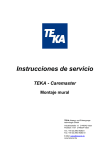
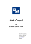
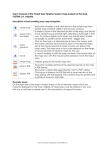
Operating Instructions
Typ
Extractor Blower
TEKA Absaug- und Entsorgungstechnologie GmbH
Industriestraße 13 D-46342 Velen
Postfach 1137 D-46334 Velen
Tel.: +49 (0) 2863 9282-0
Fax: +49 (0) 2863 9282-72
E-Mail: [email protected]
www.tekanet.de
List of contents
1.
Diagrams / description of the elements........................................................................................... 3
2.
Foreword ....................................................................................................................................... 5
3.
Function of the TEKA – Extractor blower........................................................................................ 6
4.
Safety instructions ......................................................................................................................... 6
5.
Initial operation .............................................................................................................................. 7
5.1.
Connection of the appliances .................................................................................................. 7
6.
Technical data ............................................................................................................................... 8
7.
Declaration of conformity for TEKA – extractor blower.................................................................... 9
BA_Sauggebläse_091216_GB.doc
2
16.12.2009
1. Diagrams / description of the elements
Ventilator made of silumin cast iron
Pos.1
Pos.2
Pos.3
Pos.4
Motor protective switch
Switches the ventilator on or off
Ventilator frame
Motor
Ventilator housing
BA_Sauggebläse_091216_GB.doc
Pos.5
Pos.6
Pos.7
Pos.8
3
Clamping lock
Protective grid
Castor with brake
Castor without brake
16.12.2009
Ventilator made of sheet steel
Pos.1
Pos.2
Pos.3
Pos.4
Motor protective switch
Switches the ventilator on or off
Mounting profile
Motor
Ventilator housing
BA_Sauggebläse_091216_GB.doc
Pos.5
Pos.6
Pos.7
Pos.8
Pos.9
4
Exhaust stub
Protective grid
Intake stub
Castor without brake
Castor with brake
16.12.2009
2. Foreword
One sector of extraction equipment has become very significant in recent years. The filtering of
extracted pollutants and the recycling of filtered air to the working area.
This is surely a sign that the environmental consciousness of every one of us has altered very strongly
in favour of our environment. For a long time now, no one has denied that pollution occurs during
production. However, the pollutants depend on the process that is used. One can basically distinguish
between gases and fumes (smoke). Fumes could also really be described as dust. If you examine this
dust under a microscope, you will find that they consist of very fine particles, often with a size of 1 µm or
smaller, that can enter the lungs.
The classical method of trying to improve the working conditions of polluted workplaces is general
ventilation. In this case, the general rule is a multiple change of air in the workshop, i.e. the complete
volume of air in the workshop is replaced. However, this method only achieves a small reduction in the
level of pollution within the breathing space of the user.
The same applies to “overhead” extraction, i.e. the installation of large extractor hoods above the
workplaces. This is the worst airflow imaginable, since the pollutants first pass through the breathing
space of the user, and only afterwards are they contained and extracted. This is surely not the point of
the exercise. A much more effective method than overhead/wide-area extraction is the removal of
pollutants directly at their source, with localised extraction. Both the investment and the operating costs
are substantially lower if localised extraction is used.
The environmental and workplace-safety measures are especially important requirements for successful
application of a technology, in addition to the technological optimisation of the processing method. In a
time of increasing sensitivity and tougher legislation, the task therefore lies in making an early
assessment of the potential hazards for the workplace and the environment, and reducing them as
appropriate.
BA_Sauggebläse_091216_GB.doc
5
16.12.2009
3. Function of the TEKA – Extractor blower
The TEKA – Extractor blower filter unit is primarily used for localised extraction of welding fumes. For
this purpose, the unit can be equipped with one flexible extractor hose or application-specific fittings.
Limits of application:
welding fumes with oil mist, aluminium dust, grinding dust, extraction of metallic dust, gases, water etc.
(If you are uncertain, please contact the manufacturer!)
The polluted air is sucked into the extractor hood (or application-specific fitting) and transported outside
through the extractor hose.
4. Safety instructions
When using electrical equipment, the following basic safety rules must be observed, for protection
against electric shock, injury, or fire hazards.
•
Before using the equipment, read and observe these instructions!
•
Keep the operating and maintenance instructions in a safe place!
•
Never use the extractor blower to extract easily inflammable or explosive gases!
•
Never use the extractor blower for extracting aggressive media!
•
Never use the extractor blower for extracting burning or glowing materials
•
Never use the equipment to suck up any kind of liquid!
•
Do not use the equipment for the extraction of organic substances without written approval from
the manufacturer!
•
Protect the connectors against heat, moisture, oil, and sharp edges!
•
Pay attention to the permitted supply voltage!
(Observe the data on the nameplate!)
•
Only use TEKA spare parts!
•
The exhaust vent must not be covered up or blocked!
•
Always make sure that the unit is securely mounted!
•
The mains supply cable for the unit must be checked regularly for possible damage!
•
The extractor blower must not be used if the mains supply cable is not in perfect condition!
•
Do not use the extractor blower if one or more of its components are faulty, missing, or
damaged. In any of these cases, please call the TEKA service department on ++44-(0) 28 6392 82-0.
BA_Sauggebläse_091216_GB.doc
6
16.12.2009
5. Initial operation
The extractor blower is supplied with all connections.
The extractor blower can be used in any location.
The extractor blower may be installed outdoors.
The extractor fittings and possible other accessory equipment, must be installed or mounted on the
extractor blower before initial operation.
Warning:
The extractor blower may only be operated without a hose if the intake and exhaust stubs are secured
by a grid!
5.1. Connection of the appliances
•
Connect the extractor blower with the power supply.
(Observe the information on the nameplate!)
Warning:
Work on the electrical sections must only be carried out by qualified and authorized personnel.
(Observe the data on the nameplate!)
BA_Sauggebläse_091216_GB.doc
7
16.12.2009
6. Technical data
Warning:
Observe the information on the nameplate!
Motor power
kW
Voltage V
Frequency Hz
Rated current
A
Max. airflow volume
max. m³/h
Protection
class
ISO class
0.75
230
50
2.96
2000
IP 54
F
0.75
400
50
1.71
2000
IP 54
F
0.75
500
50
1.41
2000
IP 54
F
1.1
230
50
4.2
2500
IP 54
F
1.1
400
50
2.4
2500
IP 54
F
1.1
500
50
2.1
2500
IP 54
F
1.5
230
50
5.9
3000
IP 54
F
1.5
400
50
3.8
3000
IP 54
F
1.5
500
50
2.68
3000
IP 54
F
2.2
230
50
8.3
3500
IP 54
F
2.2
400
50
4.8
3500
IP 54
F
2.2
500
50
3.6
3500
IP 54
F
3.0
400
50
6.4
4000
IP 54
F
3.0
500
50
4.9
4000
IP 54
F
BA_Sauggebläse_091216_GB.doc
8
16.12.2009
7. Declaration of conformity for TEKA – extractor blower
TEKA
Absaug - und Entsorgungstechnologie GmbH
Industriestraße 13
D - 46342 Velen
Phone:+49 2863 92820
Fax:+49 2863 928272
e-Mail: [email protected]
Internet:http://www.tekanet.de
We herewith declare in sole responsibility that the afore-mentioned product, starting from machine No.:
110000000, conforms to the following standards:
Directives on machine building:
Electromagnetic compatibility:
Directives on printing device:
Directives on low voltage:
2006/42/EG
2004/108/EG
97/23/EG
2006/95/EG
Applied harmonised standards:
-
DIN EN 349
DIN EN 983
DIN EN 12100 part 1 and npart 2
DIN EN 60204 part 1
DIN EN ISO 13857
DIN EN ISO 14121
plus further national standards and specifications:
-
DIN 45635 Part 1
This declaration will become void if changes are effected to the suction and filter systems which were
not agreed upon in writing by the manufacturer.
Velen, 16 December 2009
TEKA
Absaug - und Entsorgungstechnologie GmbH
BA_Sauggebläse_091216_GB.doc
9
16.12.2009