1
INSTALLATION AND
OPERATING INSTRUCTIONS
T7460H SETPOINT SELECTOR
DESCRIPTION
The T7460H setpoint selector is a temperature selector
equipped with operating mode switch, room temperature sensor,
and error indicator LED. It is supported by the following control
systems:
• MCR 35, 36, 40, 200
• DHC 23
• Excel 500
Not for MCR 200-61 large installations and MCR 200-62.
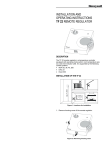
INSTALLATION OF THE T7460H
Figure 1: Locations for installation
1. Remove housing cover of the setpoint selector.
Figure 2: Removing housing cover
® U.S. Registered Trademark
EN1H-0154GE51 R0508
Copyright © 2008 Honeywell Inc. • All Rights Reserved.
T7460H – Installation and Operating Instructions
2. Screw setpoint adjuster to the under plaster distribution box.
Figure 3: Dimensions of housing
3. Connect the cable coming from the controller.
Figure 4: Wiring diagram
Wiring of the terminals:
1
2
3
Setpoint
+ 10 V
Gnd
4
5
6
not used
Room sensor
LED
4. Return cover to housing by placing top edge against backplate and snap lower part of cover onto housing (2).
Figure 5: Replacing of housing cover
EN1H-0154GE51 R0508
T7460H – Installation and Operating Instructions
OPERATION AND FUNCTIONS
Figure 6: Operating devices and indicators
1
Operating mode switch
2
LED (error indicator)
3
Temperature selector with scale
4
Temperature sensor (to the side)
T7460H in operation with systems
MCR 35, 36, 40, 200, DHC 23 and EXCEL 500
Operating mode switch
The operating mode switch allows for the selection of three
different functions:
Position Operating
mode
Auto Automatic
Daytime
Switch-off
Function
Heating is controlled by timer.
Only desired value for day applies.
Heating is switched off. In the event of
danger of frost, the heating pump and
the burner are automatically switched
on.
Note
The operating mode switch of the T7460H does not in
any way influence the domestic hot water program.
Temperature selector
The desired value can be changed only if the
operating mode switch is set to positions Auto or
respectively.
Range:
–7...+7 °C
Mid-point position:
0 °C
(in relation to controller settings)
LED
Function in operation with MCR 200: The LED is on
if the controller has detected an error.
The LED may also be used with other systems. The
input voltage is
5 – 24 V AC or DC.
EN1H-0154GE51 R0508
T7460H – Installation and Operating Instructions
T7460H in operation with Excel 500 System
If the T7460H is operated with the Excel 500 System, the temperature range and options of the operating mode switch can be
chosen to suit your needs.
In such an installation, the feedback control system of the Excel
System provides information on the current configuration of the
switch.
TECHNICAL DATA
Sensor device:
Resistance:
Temperature range:
Dimensions (H×W×D):
Installation:
NTC thermistor
20 kOhm at 25 °C
6...40 °C
103 × 98 × 28 mm
Installation on wall or
on standard 60 mm distribution box
Max. operating
temperature / humidity: 0...50 °C / 5...95% humidity
Max. storage
temperature / humidity: –35...+70 °C / 5...95% humidity
2
Electric connection:
Terminals for max. 1.0 mm
wire diameter
Protection class:
IP 30, DIN 40 050
or IEC 144
Technical data regarding the NTC thermistor:
see publication EN0B-0476GE51.
Manufactured for and on behalf of the Environmental and Combustion Controls Division of Honeywell
Technologies Sàrl, Ecublens, Route du Bois 37, Switzerland by its Authorized Representative:
Automation and Control Solutions
Honeywell GmbH
Böblinger Strasse 17
71101 Schönaich / Germany
Phone: (49) 7031 637 01
Fax: (49) 7031 637 493
http://ecc.emea.honeywell.com
Subject to change without notice. Printed in Germany
7157408
EN1H-0154GE51 R0508