1
ZAPP
WIRELESS SYSTEM
HONEYWELL EXCEL 5000 OPEN SYSTEM
SYSTEM ENGINEERING
INTRODUCTION
Organization of this Manual
This manual is organized to guide you through the
engineering of a project from start to finish or adding to or
changing an existing system. Sections “Introduction” and
“Application Steps” provide the information needed to make
accurate ordering decisions. These steps are guidelines
intended to aid understanding of the product options, bus
arrangement choices, configuration options, and the wireless
ZAPP system role in the overall EXCEL 5000 System
architecture.
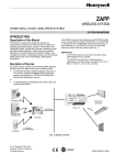
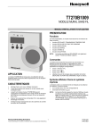
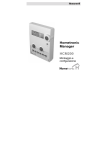
Description of Devices
The ZAPP system consists of the W7070A ZAPP Wireless
Receiver and up to eight rooms, each containing a ZAPP
room unit. There are four types of ZAPP room units:
•
the RT7070A Wireless Handheld,
•
the T7270A1001 Analog Wall Module (with temperature
sensor and setpoint),
•
the T7270A1019 Analog Wall Module (with temperature
sensor), and
•
the T7270B1009 LCD Wall Module (for HVAC, light, and
sunblind applications).
NOTE: Since the RT7070A Wireless Handheld is not
equipped with a temperature sensor, the W7070A
will receive no temperature information from a room
in which an RT7070A is not supported by an
additional T7270A1001 or T7270A1019 located in
that same room.
The W7070A receives commands from ZAPP room units
(handhelds or wall modules) and then forwards them to the
controllers (e.g. the Excel 10 or Excel 12) connected within
the same LONWORKS network (see Fig. 1).
IMPORTANT!
The W7070A may be used only in countries where use
of ISM 433 MHz band is permitted.
The W7070A currently has a radio-frequency
registration in most European countries (A, B, CH, D,
DK, E, F, FIN, IT, LUX, N, NL, and UK).
T7270B1009
hardwired
actuators
LonWorks
Excel 12
T7270A1001
T7270A1019
W7070A
wireless
communication
RT7070A
Fig. 1. System overview
® U.S. Registered Trademark
Copyright © 2006 Honeywell Inc.
All Rights Reserved
EN0B-0286GE51 R0106
ZAPP WIRELESS SYSTEM
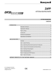
Depending upon the LONWORKS ® network configuration used,
one or two termination modules may be required (see Fig. 2).
Different connections to the termination module are
necessary, depending upon whether it is used in a single- or
double-terminated network configuration.
APPLICATION STEPS
Overview
Steps one through seven describe the engineering. These
steps are guidelines intended to aid understanding of the
product options, bus arrangement choices, configuration
options and ZAPP's role in the overall EXCEL 5000® System
architecture.
step
1
2
3
4
5
6
5
6
7
8
description
System Planning
Range of RF Transmission
LonWorks Communication
Power Supply
Configuring the W7070A
Teach-in
BROWN
ORANGE
TERMINATION
MODULE (209541B)
Fig. 2. Termination module connection (daisy-chain
network configuration shown)
Step 1: System Planning
®
NOTE: The LONWORKS network is insensitive to polarity,
eliminating installation errors due to miswiring
Plan the use of ZAPP according to the required functionality
and the sensor or actuator usage.
When planning the system layout, consider potential expansion possibilities to allow for future growth.
Wire the W7070A's LonWorks ® communications network
using level IV 22 AWG or plenum-rated level IV 22 AWG nonshielded, twisted pair, solid conductor wire.
Step 2: Range of RF Transmission
IMPORTANT!
Do not bundle wires carrying field device signals or
LonWorks communications together with high-voltage
power supply or relay cables. Specifically, maintain a
min. separation of 80 mm between such cables. Local
wiring codes may take precedence over this
recommendation.
Because of interference from other devices and the building
structure, it is not possible to exactly define the wireless
transmission range.
General Guideline
The max. distance between the W7070A and ZAPP room
units should be less than 30 meters, and there should be no
more than two walls between the W7070A and ZAPP room
units.
IMPORTANT!
Try to avoid installing in areas of high electromagnetic
noise (EMI).
RF transmission between the W7070A and ZAPP
room units may be disrupted by interference from
metal objects in the building (metal cabinets / doors,
mirrors, concrete ceilings, iron grills, aluminum
laminated plates), other radio transmitters (e.g.
wireless phones), and power switching devices.
− Establish and check radio communication of the
ZAPP room units with regards to interference, e.g.
Use LonMaker or EXCELON in conjunction with
nvoRfState.LastCommand to verify a successful
transmission from the ZAPP room units to the
W7070A.
− If interference occurs, select an alternative location
for installation.
Step 3: LonWorks Communications
The W7070A utilizes a free-topology transceiver (FTT10A)
Link Power compatible LONWORKS® network that allows daisychain, loop, and star network configurations or any
combination thereof (see also Excel 50/500 LONWORKS
Mechanisms Interface Description, Product Literature No.:
EN0B-0270GE51, for a complete description of possible
layouts and wiring details, including max. lengths).
EN0B-0286GE51 R0106
5
6
7
8
2
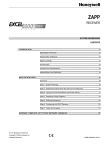
The LonWorks network is connected to terminals 5 and 7.
Terminals 6 and 8 may be used to connect further devices to
the same LonWorks network.
Step 4: Power Supply
IMPORTANT!
Local wiring guidelines (e.g. VDE 0100) may take
precedence over recommendations provided in these
recommendations.
All wiring must comply with applicable electrical codes and
ordinances. Refer to job or manufacturers’ drawings for
details. Use a min. of 18 AWG (1.0 mm2) and a max. of
14 AWG (2.5 mm2) for all power wiring.
The power supply (24 Vac [±20%], 50 or 60 Hz) is connected
to terminals 1 and 3. Terminals 2 and 4 may be used to connect further devices to the same 24 Vac power supply.
ZAPP WIRELESS SYSTEM
ZAPP RECEIVER
24 VAC
120/240 VAC
24 VAC COM
LONWORKS NETWORK IN
LONWORKS NETWORK OUT
1
2
3
4
5
6
7
8
teach-in
mode
24 VAC
24 VAC
24 VAC
24 VAC
LonWorks
LonWorks
LonWorks
LonWorks
TEACH
room
number
Fig. 5. W7070A in teach-in mode
Fig. 3. W7070A terminal assignments
NOTE: If you enter no input within 3 minutes, the W7070A
will revert back to the normal mode.
NOTE: W7070A's manufactured before date code 0438
have factory settings which do not support allocation
of the T7270B1009. In order to nonetheless allocate
a T7270B1009, you must press the teach-in button
for 20 seconds during power up. This command
deletes all previous teach-in information!
Step 5: Configuring the W7070A
The W7070A is configured using a plug-in which may be used
with CARE or any other LNS-based tool such as LonMaker™
for Windows.
If the factory pre-configuration already fits your needs,
configuration is not necessary (see Appendix).
2) Selecting a Unique Number
NOTE: If communication between the W7070A's neuron
processor and its co-processor is interrupted, the
W7070A will display an error message (see Fig. 4).
This will occur e.g. when an unconfigured W7070A is
powered up.
To resume normal operation, set the W7070A to
"configured online"
You must now assign a unique number (1 through 8) to the
given room unit by pressing the button on the W7070A as
many times necessary.
TEACH
unique
number
E
error
message
LON
NOT
Fig. 6. Assigning unique number
OK
Since the RT7070A Wireless Handheld is not equipped with a
temperature sensor, in order for the W7070A to receive
information on room temperature, you must assign the same
unique number to both the RT7070A in a particular room and
the T7270A1001 or T7270A1019 located in that same room.
The W7070A is now ready to receive teach-in messages from
the room units.
Fig. 4. Error message (no LonWorks© communication)
Step 6: Teach-In Procedure
Teach-in is a procedure required to allocate ZAPP room units
located in the various different rooms to the W7070A. Up to
eight rooms, each containing a room unit, can be allocated to
a single W7070A. After successful completion of the teach-in
procedure for each individual room unit, the W7070A will then
recognize commands it receives from them.
Teaching-in can be done as described in the following
sections or by using the plug-in.
3) Teaching-In a Room Unit
3a) Teaching-In an RT7070A
On the RT7070A, press "UP, "B," and "OK" simultaneously to
send the teach message to the W7070A.
If the teach-in was successful, the W7070A will display the
corresponding texts ("PRESENT" and "OK").
The appearance of the
symbol indicates that the device
which has been taught-in is an RT7070A.
NOTE: When using the plug-in to teach in the room units, it
is necessary that you stop teaching in a given
room unit before starting to teach in the next
room unit. This is because the W7070A will remain
in the teach-in mode for 5 minutes, and you may
accidentally teach in the device again if you do not
wait sufficiently long before teaching in the next
device.
TEACH
RT7070A
taught-in
teach-in
successful
1) Enabling the Teach-In Mode
PRESENT OK
Fig. 7. RT7070A successfully taught-in
Press the button on the W7070A for at least two seconds.
"TEACH" and “1” is displayed, thus indicating that the
W7070A is now in the teach-in mode for room 1.
3
EN0B-0286GE51 R0106
ZAPP WIRELESS SYSTEM
3b) Teaching-In a T7270A1001 or T7270A1019
In order to perform the teach-in procedure for a T7270A1001
or T7270A1019, you must first open its housing, revealing the
battery compartment and (in the top right corner) transmission
button.
If you then insert the battery or press the transmission button,
the teach message will be sent to the W7070A.
If the teach-in was successful, the W7070A will display the
corresponding texts ("PRESENT" and "OK").
The appearance of the
symbol indicates that the device
which has been taught-in is a T7270A1001 or T7270A1019.
TEACH
teach-in
successful
for incoming commands together with the room number and
the battery status of the room unit will be displayed
incoming
commands
room
number
Fig. 11. Incoming commands / battery status
De-Teaching a Taught-In Room Unit
It is possible to de-teach (revoke) a taught-in room unit. This
is done as follows:
1. Press the button on the W7070A for 5 seconds to enter
the teach-in mode.
2. Select the room you want to de-teach by pressing the
button on the W7070A as often as necessary until the
unique number of the given room unit appears in the
display.
3. Press the button on the W7070A continuously for at least
five seconds until the word "PRESENT" in the display
disappears
T7270A
taught-in
PRESENT OK
Fig. 8. T7270A successfully taught-in
symbol and the
symbol
The appearance also of both the
indicates that an RT7070A and a T7270A (to both of which
the same unique number has been assigned) have been
taught-in to the same room.
TEACH
teach-in
successful
PRESENT OK
T7270A
taught-in
Checking the Status of a Room Unit
It is possible to check the status (i.e. taught-in status, battery
level) of individual room units. This is done as follows:
1. Press the button on the W7070A. The status (including all
relevant information) of the first room will appear.
2. To check the status of the next room, press the button on
the W7070A (see also the examples in Fig. 12 through
Fig. 14).
RT7070A
taught-in
Fig. 9. T7270A and RT7070A successfully taught-in
3c) Teaching-In a T7270B1009
In order to perform the teach-in procedure for a T7270B1009,
on the RT7070A, press F and "DOWN" simultaneously for 5
seconds, thus starting the display test and sending the teach
message to the W7070A - or simply power-up the
T7270B1009.
If the teach-in was successful, the W7070A will display the
corresponding texts ("PRESENT" and "OK").
PRESENT
Fig. 12. T7270A and RT7070A taught-in for room #1;
battery level OK
The appearance of the
symbols indicates that the device
which has been taught-in is a T7270B (which incorporates
HVAC, light, and sunblind functionality)
TEACH
teach-in
successful
battery
level
T7270B
taught-in
PRESENT
Fig. 13. T7270A taught-in for room #2; battery level OK
PRESENT OK
Fig. 10. T7270B successfully taught-in
4) Completion of the Teach-In Process
PRESENT
After successful completion of the teach-in procedure for
each individual ZAPP room unit, the W7070A will then
recognize commands it receives from them. Further, a symbol
EN0B-0286GE51 R0106
Fig. 14. T7270A taught-in for room #3; battery level OK
4
ZAPP WIRELESS SYSTEM
APPENDIX: W7070A NETWORK VARIABLES
Node Object
(LonMark Object type # 0)
nviRequest
SNVT_obj_request
mandatory
Network
Variables
nvoStatus
SNVT_obj_status
NviTeachActivate
SNVT_count
optional
Network
Variables
nvoRFState
Non_SNVT
nciRmConfig
config Non_SNVT
Configuration
Parameter
value file
NciSndHrBt
config SNVT_time_sec
Fig. 15. Node Object
Room #1
Room #8
nvoSetptOffset1
SNVT_temp_p
nvoSetptOffset8
SNVT_temp_p
nvoFanSpeedCmd1
SNVT_switch
nvoFanSpeedCmd8
SNVT_switch
nvoOccManCmd1
SNVT_occupancy
nvoOccManCmd8
SNVT_occupancy
nvoLampManPos1
SNVT_switch
nvoLampManPos8
SNVT_switch
nvoSblndManPos1
SNVT_Setting
nvoSblndManPos8
SNVT_Setting
nvoFreeUse1
SNVT_switch
nvoFreeUse8
SNVT_switch
nvoSpaceTemp1
SNVT_temp_p
nvoSpaceTemp8
SNVT_temp_p
Fig. 16. Network Variables per room
5
EN0B-0286GE51 R0106
ZAPP WIRELESS SYSTEM
The following tables list all network variables associated with the W7070A.
Table A1. Configuration Network Variables associated with the W7070A
NV Name
Field Name
SH:
HB:
1
SH
HB
2
Comments
SNVT_temp_p: 0..-5 Kelvin
-5
lower temperature setpoint offset limit
.high_setpt
SNVT_temp_p: 0..+5 Kelvin
+5
upper temperature setpoint offset limit
.fanstages
enum 0..3
0 = NO FAN
1 = ONE_SPEED
2 = TWO_SPEED
3 = THREE_SPEED
THREE_
.bypass
Bit
0 = NOT_ALLOWED
1 = ALLOWED
ALLOWED
Allows the OCCUPANCY functionality to be
invoked via handheld.
.unocc
Bit
0 = NOT_ALLOWED
1 = ALLOWED
ALLOWED
Enables manually changing occupancy state
to "unoccupied."
.occ
Bit
0 = NOT_ALLOWED
1 = ALLOWED
ALLOWED
Enables manually changing occupancy state
to "occupied."
.sblnd_runtime
SNVT_time_sec: 1..240s
60
maximum movement time fur sunblind
NOTE: The sunblind runtime must be the
same in the T7270B1009, the W7070A, and
in the connected controller (e.g. an XL12).
.lamp_runtime
SNVT_time_sec: 1..60s
10
button 5 (bright): max. time for brightening
.lamp_start
1=100%
0= last level
0
button 5 (bright): Start dimming at 100% or at
last light level
.lamp_increment
SNVT_lev_percent: 0..100%
100
button 5 (bright): Step height for dimming
.free_runtime
SNVT_time_sec: 1..60s
10
button 6 (free): max. time for brightening
.free_start
1=100%
0= last level
0
button 6 (free): Start dimming at 100% or at
last light level
.free_increment
SNVT_lev_percent: 0..100%
100
button 6 (free): Step height for dimming
SNVT_time_sec
60
Length of timeout after which the W7070A
sends nvoSetptOffset and nvoSpaceTemp
out onto the network.
nciSndHrtBt
2
Default
.low_setpt
nciRmConfig
1
Engineering Units: English
(Metric) or States plus
Range
SPEED
number of possible fanspeeds: 0 = no fan /
1..3 = 1..3 speeds (plus AUTO, OFF)
Sharable (bindable) points can be set up for data sharing either a data source or a destination.
These points are sent out onto the network at a certain fixed interval (heartbeat).
EN0B-0286GE51 R0106
6
ZAPP WIRELESS SYSTEM
Table A2. Input Network Variables associated with the W7070A
NV Name
Field Name
Engineering Units:
English (Metric) or
States plus Range
Digital
State /
Value
Default
FFFFh
SNVT_Count
1..16
0, FFFF
1
SH
HB
Comments
2
W7070A supports up to eight rooms. Each
room is split into two functional areas, the
handheld area (1…8) and the sensor (wall
module) area (9…16).
NOTE: If the application supports
additional NVs (e.g. as may be the
case with customized solutions),
the actual number of supported
rooms may in fact be lower.
For ease of understanding, in this document, the term “sensor” is used for 9…16.
The assignment is as follows:
room 1: handheld 1; sensor 9
room 2: handheld 2; sensor 10
nviTeachActivate
…
room 8: handheld 8; sensor 16
To teach-in the sensor in room 3, you must
set nviTeachActivate = 11.
nviTeachActive = 0 or FFFFh: no activity /
stop process
possible range:1..16, FFFFh
The visual (LCD) behavior of the W7070A
is equal to teach-in without tools. The
result of teach-in can be read out of
nvoRfState.teached.
object_id
nviRequest
object_request
1
2
SH:
HB:
This input variable belongs to the Node
Object and provides the mechanism to
request a particular mode for a particular
object within a node.
SNVT_obj_request
0 = NODE_OBJECT
1 = ROOM1
2 = ROOM2
..
8 = ROOM8
object_request_t
RQ_NORMAL
RQ_UPDATE_STATUS
0
2
RQ_RESET
17
See above. Commanding any modes other
than the ones listed will result in an
“invalid_request” when reading nvoStatus.
Occupancy state is reset to "unoccupied"
and nvoSetPtOffset is set to 0
Sharable (bindable) points can be set up for data sharing either a data source or a destination.
These points are sent out onto the network at a certain fixed interval (heartbeat).
7
EN0B-0286GE51 R0106
ZAPP WIRELESS SYSTEM
The fixed values of the variables are described in the ZAPP Handheld User Manual (Product Literature No.: EN2B-0205GE51).
Table A3. Output Network Variables associated with the W7070A
NV Name
Field Name
Default
Engineering Units: English
(Metric) or States plus
Range
1
SH
HB
2
Comments
0xFF = no
override
X
SNVT_temp_p:
-5..+5 K due to nciRmConfig
0
x
.value
SNVT_switch.value: 0..100%
O%
x
.state
SNVT_switch.state:
0 = OFF
1 = ON
255 = NUL
NUL
x
SNVT_setting
3 = SET_UP
2 = SET_DOWN
4 = SET_STOP
255 = SET_NUL
SET_NUL=
no action
x
Enables SUNBLIND functionality.
SNVT_switch.value: 0..100%
0
x
Enables LIGHT functionality.
SNVT_switch.state:
0 = OFF
1 = ON
255 = NUL
NUL
x
Enables LIGHT functionality.
.value
SNVT_switch.value: 0..100%
0
x
Enables LIGHT functionality.
.state
SNVT_switch.state:
0 = OFF
1 = ON
255 = NUL
NUL
x
Enables LIGHT functionality.
SNVT_temp_p 0..40° C
invalid
x
.BatteryState1
...
.BatteryState16
Bit:
0 = battery ok
1 = battery low
0 = ok
.teached1
...
.teached16
Bit:
1 = taught
0 = no device taught
0, but saves
value over
power down
nvoOccManCmd*
SNVT_occupancy:
0
= OC_OCCUPIED
1
= OC_UNOCCUPIED
2
= OC_BYPASS
Enables OCCUPANCY functionality.
0xFF = OCC_NUL
nvoSetPtOffset*
nvoFanSpeedCmd*
nvoSblndManPos*
nvoLampManPos*
nvoFreeUse*
nvoSpaceTemp*
nvoRfState
3
x
Enables SETPOINT OFFSET
functionality.
Manual user override of fanspeed.
x
Contains info on room temperature of
taught-in wall module.
Battery condition for handheld (1…8)
or sensor (9…16) in the rooms.
NOTE: If there is no communication
from the wall module (e.g. because
battery was removed), the battery
state will be set to 1.
room 1: handheld 1; sensor 9
room 2: handheld 2; sensor 10…
room 8: handheld 8; sensor 16
.lastRfDevice
Byte:
0..16
Contains info on origin of last
message received by W7070A
room 1: handheld 1; sensor 9
room 2: handheld 2; sensor 10…
room 8: handheld 8; sensor 16
1
SH: Sharable (bindable) points can be set up for data sharing either a data source or a destination.
2
HB: These points are sent out onto the network at a certain fixed interval (heartbeat).
3
:
If there is no RF communication with the wall module, the battery state will be set to 1. This may require up to 2 hours.
*Each of these variables exists for rooms 1 through 8 and has a single-digit index of 1..8.
EN0B-0286GE51 R0106
8
ZAPP WIRELESS SYSTEM
Table A3 (continued). Output Network Variables associated with the W7070A
NV Name
nvoRfState
Field Name
.lastCommand
Engineering Units: English
(Metric) or States plus Range
Default
.TeachActive
2
Comments
HB
Contains info on last message received by
W7070A.
Enum:
0 = OFFS_HIGHER
1 = OFFS_LOWER
2 = OFFS_ZERO
3 = OFFS_MIN
4 = OFFS_MAX
5 = FAN_HIGHER
6 = FAN_LOWER
7 = FAN_AUTO
8 = FAN_MAX
9 = FAN_OFF
10 = OCC_BYP
11 = OCC_UNOCC
12 = OCC_NUL
13 = OCC_OCC
14 = LIGHT_MAX
15 = LIGHT_MIN
16 = LIGHT_START_DIM
17 = LIGHT_STOP_DIM
18 = SBL_UP
19 = SBL_DOWN
20 = SBL_STOP
21 = OFFICE_STYLE_1
22 = OFFICE_STYLE_2
23 = FREE_MAX
24 = FREE_MIN
25 = FREE_START_DIM
26 = FREE_STOP_DIM
27 = DIRECT_SETPT
28 = ROOM_TEMP
255 = CMD_NUL
nvoRfState
1
SH
SNVT_count: 0..16
Contains info on the number of the room
unit currently in the teach-in mode.
0 = no teach-in process.
room 1: handheld 1; sensor 9
room 2: handheld 2; sensor 10…
room 8: handheld 8; sensor 16
.major
nroSwVersion
W7070A neuron application software
version
.minor
.bug
.object_id
0 = NODE_OBJECT
1 = ROOM1
2 = ROOM2
3 = ROOM3
...
8 = ROOM8
.invalid_id
0 = VALID_ID, 1 = INVALID_ID
.disabled
0 = ENABLED, 1 = DISABLED
nvoStatus
1
SH:
2
HB:
Sharable (bindable) points can be set up for data sharing either a data source or a destination.
These points are sent out onto the network at a certain fixed interval (heartbeat).
9
EN0B-0286GE51 R0106
ZAPP WIRELESS SYSTEM
ACCESSORIES, AGENCY LISTINGS,
ABBREVIATIONS, AND LITERATURE
Honeywell
XAL-Term
Accessories
Wall Holder for Handhelds
4
3
The RT 70-HRD20-Wall includes 10 wall holders for the
RT7070A.
3
1
shield
0
plug-in
jumper
removable screw-type
3-pole terminal block
4
5
shield
6
LON
Termination
FTT/LPT Bus
FTT/LPT Free
Park Position
L
O
N
L
O
N
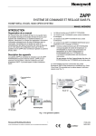
LONWORKS® Termination
One or two LONWORKS® terminations are required, depending
on the given LonWorks bus layout.
Two different LONWORKS® terminations are available:
•
LONWORKS® termination module, order no.:
209541B
•
LONWORKS® connection / termination module (can be
mounted on DIN rails and in fuse boxes),
order no.:
XAL-Term
Fig. 17. Lonworks® connection and termination module
Agency Listings
Table 1 provides information on agency listings for wireless ZAPP system products.
Table 1. Agency listings
Devices
Agency
W7070A
T7270A
T7270B
CE
FCC
Comments
General Immunity per European Consortium standards EN50081-1 (CISPR 22 Class B) and
EN 50082-1:
1992 (based on Residential, Commercial, and Light Industrial).
EN 61000-4-2
IEC 1000-4-2 (IEC 801-2) Electromagnetic Discharge.
EN 50140, EN 50204
IEC 1000-4-3 (IEC 801-3) Radiated Electromagnetic Field.
EN 61000-4-4
IEC 1000-4-4 (IEC 801-4) Electrical Fast Transient (Burst).
Radiated Emissions and Conducted Emissions.
EN 55022:
1987 Class B.
CISPR-22:
1985.
Complies with requirements in FCC Part 15 rules for a Class B computing device.
Manufactured for and on behalf of the Environmental and Combustion Controls Division of Honeywell Technologies Sàrl, Ecublens, Route du Bois 37, Switzerland by its Authorized Representative:
Automation and Control Solutions
Honeywell GmbH
Böblinger Straβe 17
D-71101 Schönaich / Germany
Phone: (49) 7031 637 - 01
Fax:
(49) 7031 637 - 493
http://europe.hbc.honeywell.com
Subject to change without notice. Printed in Germany
EN1B-0286GE51 R0106