1
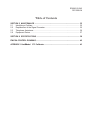
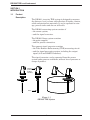
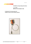
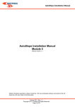
Leader in
Level Measurement
For Assistance Call 1-800-553-9092
Outside North America 1-215-674-1234
Installation and
Operating Instructions
Series DR1200 (TDR)
Guided Micropulse Level Instrument
for
Two-Wire Control Systems
(215) 674-1234 Outside North America
(800) 527-6297 US and Canada
http://www.drexelbrook.com
e-mail:[email protected]
The DR1200 level gauge is designed solely for measuring the distance, level, volume and
reflection of liquids, solids and particulate materials. The DR1200 level gauge does not
form part of an overfill protection system. Special codes and regulations apply to its use in
hazardous areas. Responsibility as to suitability and intended use of these level gauges
rests solely with the user. Improper installation and operation of our level gauges may lead
to loss of warranty.
AMETEK Drexelbrook makes no warranty of any kind with regard to the material contained
in this manual, including, but not limited to, implied warranties or fitness for a particular
purpose. Drexelbrook shall not be liable for errors contained herein or for incidental or
consequential damages in connection with the performance or use of material.
Copyright 2001 AMETEK Drexelbrook
EDO#3-02-242
DR1200-LM
Series DR1200 (TDR)
Guided Micropulse Level Instrument
for
Two-Wire Control Systems
205 Keith Valley Road Horsham, PA 19044
An ISO 9001 Certified Company
US Sales
24 Hour Service
International
Fax
E-mail
Web
800-553-9092
800-527-6297
215-674-1234
215-674-2731
[email protected]
www.drexelbrook.com
EDO#3-02-242
DR1200-LM
Table of Contents
SECTION 1 INTRODUCTION ............................................................................................. 1
1.1
Product Description ................................................................................................... 1
1.2
Model Number ........................................................................................................... 2
1.3
Probe Selection Guide .............................................................................................. 3
SECTION 2 INSTALLATION ........................................................................................... 4
2.1
Unpacking ................................................................................................................. 4
2.2
Installation Considerations ........................................................................................ 4
2.2.1 Measured Variable (Input)............................................................................... 4
2.2.2 Measuring Range (Input) ................................................................................ 4
2.2.3 Dead Zone (Input) ........................................................................................... 4
2.2.4 Out of Range Performance (Input) .................................................................. 4
2.2.5 HART® Communications (Output).................................................................. 5
2.2.6 Service Diagnostics (Output) .......................................................................... 6
2.3
Installation Guidelines ............................................................................................... 7
2.4
Wiring ........................................................................................................................ 9
2.4.1 Electrical Connection ...................................................................................... 9
SECTION 3 OPERATION .................................................................................................. 11
3.1
Start-up .................................................................................................................... 11
3.2
Calculation of the Measured Value .......................................................................... 11
3.3
Warning Messages during Measurement ................................................................ 12
3.4
Error Messages during Measurement ...................................................................... 13
3.5
Symptoms/Faults during Start-up or Measurement .................................................. 14
SECTION 4 COMMUNICATION ...................................................................................... 16
4.1
Loop Requirements ................................................................................................. 16
Safety Barriers ......................................................................................................... 16
4.1.1 Interface Adapter ........................................................................................... 18
4.1.2 Load Resistance ........................................................................................... 18
4.1.3 Multidrop Communication ............................................................................. 18
4.2
PC Software ............................................................................................................ 20
4.2.1 Software Installation ..................................................................................... 20
4.2.2 Table of Configuration Parameters ............................................................... 20
4.2.3 Software Configuration Examples ................................................................ 24
4.2.4 Software Parameter Descriptions ................................................................. 26
4.2.5 General Status Message............................................................................... 33
4.2.6 Transmitter-specific Status Messages .......................................................... 33
EDO#3-02-242
DR1200-LM
Table of Contents
SECTION 5 MAINTENANCE ........................................................................................... 35
5.1
Identifying a Problem ............................................................................................... 35
5.2
Replacement of the Signal Converter ...................................................................... 35
5.3
Telephone Assistance ............................................................................................. 36
5.9
Equipment Return.................................................................................................... 37
SECTION 6 SPECIFICATIONS ....................................................................................... 38
FM/CSA CONTROL DRAWING ........................................................................................ 42
APPENDIX 1 Hart® Model
275 Calibrator ....................................................................... 43
DR1200 TDR Level Instrument
SECTION 1
INTRODUCTION
1.1
Product
Description
The DR1200 two-wire TDR system is designed to measure
the distance, level, volume and reflection of liquids, slurries,
solids and particulate materials. It can be operated on storage, process tanks and also on still wells.
The DR1200 measuring system consists of
• the sensor system,
• and the signal converter.
The DR1200 flange system contains
• the probe support,
• and the process connection.
The compact signal converter contains
• the Time Domain Reflectometry (TDR) measuring circuit
• and the signal processing system, including the output
signal (4-20 mA HART® interface).
The signal converter can be separated from the sensor
system under process conditions, without loss of pressure or
escape of product.
Converter
(1-inch NPT
or Flange
connection)
Probe
Figure 1-1
DR1200 TDR System
1
DR1200 TDR Level Instrument
1.2
Model Number
Instrument
DR1200
Internal code
4
Probe Construction
1 Single Rod
maximum length 10'
2 Single Cable maximum length 80' (4mm OD)
3 Coaxial
maximum length 20'
4 Twin Cable
maximum length 80'
6 Single Cable maximum length 80' (8mm OD)
Material
1 316 SS (standard for Cable probe)
2 316L SS (standard for Rod probe)
Connection (ANSI)
2 1" NPT
3 1 1/2" NPT
A 2" 150#
B 2 1/2" 150#
Length
0
0'
1
3'
2
7'
3
10'
4
13'
C 3" 150#
D 4" 150#
E 6" 150#
5
6
7
8
A
B
C
D
E
F
17'
20'
23'
26'
30'
33'
36'
40'
43'
46'
G
H
K
L
M
50'
53'
56'
59'
63'
Incremental Length
0
1
2
3
4
5
20"
0"
6
24"
4"
7
28"
8"
8
32"
12"
A
35"
16"
Pressure Rating
2
232 psi (standard)
3
580 psi
Sealing
1
Viton
2
Kalrez
Counter Weight
0 Without
3 D 2" x L 10" (8 mm cable/solids)
1 D 1" x L 4" (standard)
5 Turnbuckle
6 Tie-down (clamps included)
2 D 2" x L 2" (Twin Cable)
Cable connection
1 DIN Connector (snap-on plastic cable gland)
2 M 16 (includes junction box)
3 1/2" NPT (includes junction box)
Application
1
Liquids
2
Solids
Approvals
2 FM
0 Without
3 CSA
1 Cenelec/Atex
Precision
1 15 mm (standard)
2 5 mm
Flange Temperature
1 194ºF (90ºC) standard
2 275ºF (135ºC)
Indicator
0 Without
DR1200
4
0
2
N
P
R
S
T
66'
69'
73'
76'
80'
DR1200 TDR Level Instrument
1.3
Probe selection guide
Coax
Twin Cables
Single Cable or Rod
Recommended Applications
Only for clean, non-viscous
liquids.
For high silo or tank with
liquid or granules.
For all fine powder applications.
1. Connection size is less
than three inches.
2. Liquid movements, acting
like stillwell.
3. Liquid or vapors spray
near the probe.
4. Flow inside vessel like
oil/water separators.
5. Can be heat tracing.
6. Contact with metallic
part or tank wall.
7. High magnetic field
around.
8. CE approval in plastic
tanks.
9. Very low dielectric
liquids.
10. Foam applications.
1. Same as rod, but over 20
and up to 80 feet.
2. For smaller tanks with no
clearance for rigid probe.
3. For side installation with
bent type DR1200 (maximum 20 feet on liquid).
1. For all fine powder applications greater than 20
feet.
2. For all very viscous
liquids like liquid sugar.
3. To build a coax version
with an existing
stillwell (calibration
required).
4. Very corrosive liquids
with FEP coating.
5. Crystallizing acids with
FEP coating.
Non-Recommended Applications
1. Crystallizing liquids.
2. Severe coating.
3. Powders.
1. Small connection flange
with nozzle.
2. Agitated tank without
anchoring.
1. Long and small diameter
nozzle installation (mini
mum recommended
flange four inches or see
item 2 below.
2. Maximum nozzle height
based on its diameter.
The calculation is:
h = (Lxd) + 140mm.
4xa
L = Probe length (mm).
d = Nozzle diameter (mm).
a = Flange eccentricity from
tank center (mm).
Application Examples
1. Tanks less than 20 feet.
2. LPG, LNG, Solvent,
NH3, Fuel oil, Foam,
Alcohol, Oil/Water
separators, displacer,
open channel measurement, thread connection
installation.
1. Tank farm.
2. LPG, LNG, NH3.
spheres, beer, alcohol.
3. For very high temperature
applications with single
cable construction.
3
1. Cement, limestone,
flyash, alumna, etc...
2. Acids.
3. Liquid sugar, honey,
syrups.
DR1200 TDR Level Instrument
SECTION 2 INSTALLATION
2.1
Unpacking
Carefully remove the contents of the shipping carton and
check each item against the packing list before destroying
any packing material. If there is a shortage or damage,
report it to the factory immediately.
When handling the DR1200 TDR instrument avoid hard
blows, jolts, impacts,
2.2
Installation Considerations
2.2.1 Measured Variable (distance, level, volume)
(Input)
The primary measured variable is the distance between a
reference point (e.g. tank mounting flange) and a reflecting
surface (e.g.surface of the level).
Volume measurements are possible by entering a conversion
table (maximum 20 points).
The strength of the reflected signal can be measured for
qualitative assessment of the process material.
(Only available with HART® communication).
2.2.2 Measuring Range (0.5 to 80 feet)
(Input)
Minimum tank height is 0.5 feet.
The useful range depends on the sensor type, the reflection
properties of the process material, the installation position,
and the presence of interfering reflections.
2.2.3 Dead Zone
(Input)
The dead zone distance is the minimum measured distance
between the mounting flange (reference point) and the
surface of the process material.
A
For twin probe:
For twin probe:
For single probe:
For single probe:
For coax system:
K>10
K<10
K<10
K>10
= 0
12 inches.1
6 inches.1
16 inches.1
12 inches.1
for all K.1
B
•Avoid a nozzle length (A) greater
than six inches.
•Measurement B should not be
less than three inches.
•Measurement B should be greater
than measurement A.
1
These are minimum values. Default value is 16 inches.
4
DR1200 TDR Level Instrument
2.2.4 Out-of-range Performance
(Input)
When the level measuring range is exceeded (including
flooding) the measured value remains at the dead zone.
If the measured value drops below the level range, it
remains at the set lower range limit (distance = tank height).
2.2.5 HART® Communication
(Output)
Figure 2-2 shows an overview of the digital communications
output for the DR1200 TDR level instrument.
4 to 20 mA
+ HART®
4 mA
+ HART®
Converter
HART
COMMUNICATOR
LAPTOP PC
PC STAR 2 or HART®-specific
software and operating devices
HART
COMMUNICATOR
LAPTOP PC
HART®-Master
Point-to-Point
Multidrop
Figure 2-2
DR1200 TDR Instrument
Communications Output Options
There are two ways of using the HART® communications
protocol with a DR1200 readar instrument. All versions with
HART® protocol can be operated with the PC-STAR 2 PC
program.
5
DR1200 TDR Level Instrument
2.2.5 HART® Communication (cont.)
(Output)
a) As a point-to-point connection between the DR1200 and
the HART® Master equipment.
HART®
Master
4 to 20 mA
Figure 2-3
Point-toPoint HART® Communication
b) As a multipoint connection (multidrop) with up to 15
devices (DR1200 or other HART® equipment), in parallel on
a 2-wire bus:
HART®
Master
4 mA
4 mA
Other
HART®
Device
4 mA
4 mA
Other
HART®
Device
Figure 2-4
Multidrop HART® Communication
2.2.6 Service Diagnostics
(Output)
Service information can be accessed using the following:
· Current output: error signal 22 mA.
· Digital interfaces: interrogation of error flags.
6
DR1200 TDR Level Instrument
2.3
Installation Guidelines
The DR1200 TDR instrument is designed for field mounting:
• It should be mounted in a location as free as possible from
vibration, corrosive atmospheres, and any possibility of
mechanical damage.
• In case of direct exposure to sunshine, a sunshade is
recommended.
• For convenience at start-up, mount the instrument in a
reasonably accessible location.
• Mounting: See Figure 2-5.
12 (304)
Twin
Rod/Cable
4 inch
minimum
Coaxial
Cable
0 inch
minimum
Single
Rod/Cable
12 inch
minimum
Avoid bending.
No interference
restrictions.
7
DR1200 TDR Level Instrument
2.3
Installation Guidelines (cont.)
For best results, mount the
DR1200 radar instrument without
a nozzle and directly mounted in
a 1-inch NPT welding socket.
A
B
•Avoid a nozzle length (A)
greater than 6 inches.
•Measurement B should not
be less than 3 inches.
•Measurement B should be
greater than Measurement A.
When mounting in an agitated vessel or stilling well:
•Fix or center the end of the probe.
•Avoid touching the side vessel wall or stilling well.
8
DR1200 TDR Level Instrument
2.4
Wiring
2.4.1 Electrical Connection
The electrical connection for supply power is made in the
terminal compartment of the signal converter.
CAUTION
When using in a hazardous area, only certified
intrinsically-safe equipment may be connected
to the DR1200 instrument.
Two versions of the electrical connection are available (see
Figures 2-6 & 2-7):
1.
NPT connector: ½-inch (ISO16)
•Terminals: conductor size: 16 AWG maximum
• High Integrity Ground: U-clamp terminal
(10 AWG maximum) at "neck" of signal converter.
• Cable entries: ½-inch NPT (with standard cable gland:
cable clamping area = 8 to 10 mm).
• Signal cable shielding: possible current loop cable shield
can be connected to ground.
1.
2.
3.
Ground is directly connected with
the signal connector housing and
also with the flange system of the
instrument. To avoid ground loops,
do not connect a cable shield at
both cable ends.
Remove the four retaining screws and
open the terminal compartment.
Connect the current loop to the
terminal block. Use ferrules to protect
the cable ends. No polarity.
Close the terminal compartment.
Retaining screw
Terminal
For Ex/XP applications, only the
intrinsically safe 2-wire loop must be
connected to the terminal 1 and 2.
The ground terminal and terminal 3
are not connected.
Ground
Figure 2-6
Connector Wiring
9
DR1200 TDR Level Instrument
2. DIN Connector (Snap-on plastic cable gland)
•Terminals: conductor size:
14 AWG maximum
1.5 mm² maximum
• "Ex" equipotential bonding: U-clamp terminal (10 AWG
maximum) at "neck" of signal converter.
• Cable entries: 1x M16x1.5 (with standard cable gland:
cable clamping area = 4 to 8 mm).
• Signal cable shielding: possible current loop cable shield
can be connected to ground.
Power supply:
1. Remove the screw P and lift off the connector from the signal
converter.
2. Put a screwdriver in F and separate N from R.
3. Connect the current loop to terminals 1 and 2 (there’s no
polarity to respect). Use ferrules to protect cable ends.
Terminal 3 remains non-connected.
4. Re-assemble N and R.
5. Put the seal in place, connect R to the signal converter and
screw P .
The earth terminal E is directly connected with the signal connector housing and also
with the flange system of the instrument. In order to avoid earth current loops a possible
cable shield must not be connected at both cable ends.
For Ex applications only the intrinsically safe 2-wire loop must be connected to terminals
1 and 2. The earth terminal E as well as terminal 3 remains non-connected.
2
R
P
3
3
N
2
1
F
Figure 2-7
DIN Connector Wiring
10
1
E
DR1200 TDR Level Instrument
SECTION 3
OPERATION
3.1
Start-up
After the DR1200 TDR instrument has been switched on, the
current output is fixed to 22 mA during 13 seconds. The
current output is then driven to probe length until the level
has been found. Finally, the current output approaches the
measured value. Full measuring accuracy is obtained after
46 seconds operating time with default parameters (time
constant=10 seconds).
3.2
Calculation of the
Measured Value
Refer to Figure 3-1. The DR1200 instrument measures time
between reflections and converts it to a distance or a level
information with the following formulas:
Delta T:
Calspeeds
Offset
Epsilon R
Time between Initial Pulse and Level Pulse
(mS).
(Electronic Calspeed) x (Mechanic Calspeed)
(mS/mm).
Distance between Initial pulse and bottom sur
face of the flange (mm).
Dielectric constant of first medium under the
flange, normally 1.00.
Delta T
Offset
Calspeeds
Distance
Epsilon R
Level
Tank Height
Distance
Figure 3-1
Calculation of the Measured Value
11
DR1200 TDR Level Instrument
3.2
Calculation of the Measured Value (cont.)
The measured time between the initial pulse and the level
pulse is translated in millimeters by the Calspeed setting.
This primary distance is corrected by the offset and then
standardized to the reference point ( = flange). This primary
distance is divided by the Epsilon R square root (if there is
only one product in the tank, the Epsilon R is 1.00 [air]).
The level is calculated as the difference between tank height
and distance. All parameters (excepted Delta T) are accessible via the digital communication menus.
3.3
Warning Messages during Measurement
Status Message
Configuration Changed
More Status Available
Definition of Message
Configuration parameter was changed.
Command 48 must be executed to empty the
status. (refer to Watch Status).
Primary Variable Analog Output Fixed
•Device is set in Multidrop Mode,
(Polling Address ≠ 0).
•Fixed Current Mode is entered,
(during Loop Test and DAC Trim).
Analog Output Saturated
During normal operation, the maximum value for
the analog output is 20mA. The analog output
saturation error flag is set in case the measurement
exceeds the signal current output range.
First Start
This message appears only when the serial
number is 0 or 16777215.
Tank Full
The DR1200 indicates that the level is in the Dead
Zone. The tank is full.
Tank Empty
The DR1200 indicates that the level is below the
probe end. The DR1200 makes a measure only to
the end of the probe--not to the bottom of the tank.
Level Lost
The DR1200 loses the level signal. Message is
displayed when there is no signal with an
amplitude higher than the threshold value.
Measuring values are frozen. If the mode 4-20mA/
error 22mA is selected then the current output is
fixed to 22mA after the selected delay time.
12
DR1200 TDR Level Instrument
3.4
Error Messages during Measurement
The following table lists the error meassages that can trigger
the current ouput to be set to 22 mA if the mode 4-20/Error22 is
selected. Measuring values are then frozen. Consult Factory
Service.
Status Message
EEPROM Error
Definition of Message
Start-up error. Problem with non-volatile memory.
RAM Error
Start-up Error. Problem with internal microcontroller
memory.
Start-up Error. Problem with internal microcontoller
memory.
ROM Error
Checksum Error
Bank Customer 0
Start-up Error. Problem with the EEPROM or with the
parameter that recalls the saved EEPROM.
Parameters are saved in a non-volatile memory
(EEPROM). There are 4 banks, two for each type of
parameters (customer or factory). If there is a problem
with the first bank (0), then the DR1200 gets the
parameters values from the second bank (1). If the
DR1200 indicates only a problem with the first bank, then
it has succeeded to get all the parameters from the
second bank. In this case, the device can measure.
Check sum Error
Bank Factory 0
Start-up Error. Problem with the EEPROM or with the
parameter that recalls the saved EEPROM.
Parameters are saved in a non-volatile memory
(EEPROM). There are 4 banks, two for each type of
parameters (customer or factory). If there is a problem
with the first bank (0), then the DR1200 gets the
parameters values from the second bank (1). If the
DR1200 indicates only a problem with the first bank, then
it has succeeded to get all the parameters from the
second bank. In this case, the device can measure.
Check sum Error
Bank 1
Start-up Error. Refer to Bank 0.
Restart the device several times.
Check sum Error
Factory 1
Start-up Error. Refer to Bank 0.
Restart the device several times
Digitizing Error
Sampling audio signal error. The electronics is not getting
a valid image of the audio signal. The measurement
could be incorrect.
Gain Error
Hardware problems with the signal front end amplifier.
One of the four amplifications is not working correctly.
13
DR1200 TDR Level Instrument
3.4
Error Messages during Start-up or Measurement Cont.
Status Message
Offset Error
Definition of Message
Problem with the electronic offset of the signal.
Positive Voltage Error
+3 Volts power supply is out of limit.
Negative Voltage Error
-3 Volts power supply is out of limit.
VCO1 Voltage Error
Problem with the time base.
VCO2 Voltage Error
Problem with the time base.
Delay Out of Limits
Problem with the time base.
Reference Not Found
Problem with the time base.
Flange Not Found
Problem with the time base. Mechanical problem (bad
contact) between the converters electronic block and the
flange connection.
Update Failure
The DR1200 is not able to measure.
3.5
Symptoms/Faults during Start-up or Measurement
Symptom/Fault
Current Output Value
< 4mA
Cause
Calibration of the current
output is incorrect
Connection of the device
is incorrect.
Corrective Action
Executes the calibration with
the specialist rights or contact
Factory Service.
Check the connection
between the device and the
power supply.
No power supply.
Current Output
reads 22 mA
An error has occurred.
Current ouput reads
22 mA (cont.)
Device isn’t in start-up phase.
14
The range 4-20mA/error
22mA is selected. Check the
status by selecting F8 (PC
software) or enter the Status
menu for the HART®
Calibrator.
Wait 50 seconds. If the current
If the current value drops to a
value between 4 and 20 mA,
and goes immediately back
to 22mA, call Factory Service.
DR1200 TDR Level Instrument
3.5
Symptoms/Faults during Start-up or Measurement (cont.)
Symptom/Fault
Value at the current output
does not correspond to
the value at the display.
Cause
Settings of the current output
are incorrect.
Corrective Action
Configure output as described
in Analog Output parameter.
Data communication via
digital interface is not
working.
Communication parameters of
Check computer setting
the computer are set incorrectly. (polling address).
Bad connection to the interface. Check connection.
Current output value is < 4mA
Consult Factory Service.
Current output value is = 22mA Device isn’t in start-up phase,
wait 50 seconds and try again.
If the problem persists, contact
Factory Service.
DR1200 indicates an
incorrect level value.
DR1200 measures a non-valid
signal.
•Increase the Detection Delay
and Dead Zone with the same
ratio or increase the Threshold
level if the full measurement
range is essential.
•Threshold level must be
adjusted so that it masks the
disturbances but also to give
enough head room for the level
pulse.
•Very large pulses along the
measurement signal (same
amplitude as the initial pulse)
can be caused by a probe
which is touching the nozzle or
the tank side (see 2.3
Installation Guidelines).
The tank is empty, and the A valid pulse was found.
DR1200 indicates a level.
Check the probe for disturbances
such as heating tubes or
product build-up (clogging).
Adjust the Threshold (dynamic
configuration menu).
The tank is full, and the
Threshold is not adjusted.
DR1200 indicates a level
or empty tank.
Adjust Threshold.
The tank is not empty or Threshold is not adjusted.
not full, and the DR1200
indicates an empty or full tank.
Adjust Threshold.
15
DR1200 TDR Level Instrument
SECTION 4
COMMUNICATION
4.1
Loop Requirements
•nominal power supply voltage Vinput : 24 Vdc
35 Vdc
•maximum Vinput :
•minimum Vinput :
see graph in Figure 4-1.
Input voltages above 35 Vdc or below the specified voltage
may damage the instrument; cause a fault measurement or
trigger the instrument to reset.
loop resistance Rloop:
minimum Rloop:
maximum Rloop:
HART® Communication
resistor RHART®:
RHART® + Rcable + Rmeter
0 ohms
750 ohms
250 ohms
(recommended)
The graph in Figure 4-1 specifies the minimum voltage at the
terminals of the DR1200 instrument. The voltage drop over
the total loop resistance (Ampere-meter resistance Rmeter plus
wiring resistance Rcable plus HART® communication resistance
RHART®) should be considered for the calculation of the minimum power supply voltage.
The voltage of the power supply has to be at a loop current of
at least 20 mA:
Vsupply min20 = 20 mA x 250 ohms + Vinput min20 = 5 V + 10 V = 15 V
In order to cover the full current range of 4 to 22 mA the
voltage drop at 4 mA has to be verified.
Vsupply min4 = 4 mA x 250 ohms + Vinput min4 = 1 V + 18 V = 19 V
With a loop resistance of 250 ohms, a power supply voltage
of 19 V is sufficient to supply the 4 to 20 mA range of the
instrument.
Safety Barriers
Use the graph in Figure 4-1 to determine which safety barrier can be used with the DR1200 instrument. Most of the
barriers are specified to deliver a minimum output voltage at
20 mA loop current Vout min20. The output voltage at 4 mA must
also be specified or it can be calculated with the value of the
internal series barrier resistance.
Use only converters with HART® barriers. The PCSTAR 2
software or the HART® communication tools will not operate if
the converter is not equipped with this option.
16
Voltage
Figure 4-1
Loop Requirements
17
8
9
0
10
11
12
13
14
15
16
17
18
19
20
2
1
2
4
6
8
12
14
loop current [mA]
10
minimum input voltage V
(measured at DR1200 terminals)
with 0 ohms loop resistance
DREXELBROOK
Entity Parameters:
Vmax
= 30V
Imax
= 150mA
Pmax
= 1W
Ci
= 10.5 nF
Li
= 10uH
16
Power/Signal Terminals
Not Polarity Sensitive
18
20
22
F2
F3
DEF
8
.
>
*_
: +
3
YZ/
6
PQR
9
GHI
>
F4
OR
HART
Modem
Maximum Voltage @ 4mA:
.004A X Loop resistance +18V = Voltage required at 4mA
(Example: 0.004 X 250 ohms +18V (from chart) = 19V
Calculate required voltage:
Minimum Voltage @ 20mA:
0.02A X Loop resistance + 10V = Voltage required at 20mA
(Example: 0.02 X 250 ohms +10V (from chart) = 15V
Voltage Requirements:
IBM compatible
Minimum 0 ohms,
Maximum 750 ohms
Maximum 35 Vdc
Minumum - see chart
401-700-21
250 ohm
377-4-16 smart
377-4-15 non-smart
PC Star 2
Software
(included)
RHART
Nominal
24VDC
supply
NON HAZARDOUS
Optional
Intrinsic
Safety
Barrier
Loop Resistance:
0
<
2
# %&
5
VWX
1
MNO
4
STU
JKL
7
O
ABC
I
HART Communicator
F1
R Load
HAZARDOUS
DR1200 TDR Level Instrument
DR1200 TDR Level Instrument
4.1.1 Interface Adapter
The Smart Converter and the black Viator modem are powered
from the serial interface on the computer, which must be able to
supply the appropriate operating current with an adequate
voltage level.
For the Smart Converter:
• The serial interface must be capable of supplying a current
of approxiamately 10 mA.
• The power is taken from one or several of the following
terminals: RTS, TXD, DTR.
• The voltage to GND at at least one of these terminals must
be a minimum of +4.8 V in operation.
• PC-CAT must be used with the setting RTS not inverted.
For the black Viator RS232 Interface to HART:
• The serial interface must be capable of supplying a current
of minimum 1.5 mA.
• The power is taken from one or both of the following
terminals: DTR, RTS.
• The voltage to GND at at least one of these terminals must
be a minimum of +4 V in operation.
• The RS232 output of the PC (DTR and RTS) must be
current-limited to +/- 10 mA.
• PC-CAT must be used with the setting RTS inverted.
Pin assignment of above terminals:
9-pin
25-pin
GND
=5
= 7
RTS
=7
= 4
TXD
=3
= 2
DTR
=4
= 20
4.1.2 Load Resistance
To successfully communicate between a PC and level instrument via the current output, an appropriate resistance in the
4-20 mA loop is necessary.
The current is modulated directly, in accordance with the
HART® conventions. The signal amplitude is proportional to
the resistance and with an open loop (or a too high load) the
signal breaks down. A resistance of minimum 120 ohms is
necessary for PC communication. The HART® conventions
define a load of nominal 250 ohms, minimum 220 ohms.
4.1.3 Multidrop Communication
The DR1200 instrument can be configured in a multidrop
connection with up to 5 devices (DR1200 or other HART
equipment) in parallel on a 2-wire bus. (HART Foundation
allows up to 15 devices to be connected.)
18
DR1200 TDR Level Instrument
4.1.3 Multidrop
Communication
(cont.)
All instruments in multidrop mode must have previously
been configured with addresses different from each other
(address must not be "0" because "0" is an address used only
for point-to-point mode, where 4-20mA output is valid).
In mulitdrop mode, only digital information is used (4-20mA
output is not valid in this case, the current output of each
instrument is set to 4mA).
1.
Configure each instrument in point-to-point mode. Set
the address of the device (do not use "0").
HART®
Master
2.
Multidrop the connection of up to 5 devices (DR1200 or
other HART® equipment), in parallel on a two-wire bus.
HART®
Master
4 mA
4 mA
Other
HART®
Device
4 mA
4 mA
4 mA
Other
HART®
Device
During start-up in a multidrop configuration, each DR1200
instrument draws a current of 22mA for 25 seconds, then the
instrument drops to a fixed value of 4mA.
Looking at an example of the start-up and assuming that five
DR1200 instruments are connected, there would be a current
draw of (5 x 22mA = 110mA) for 25 seconds.
Adding the 250 ohm resistor to the equation and the constant
power supply voltage (24V) voltage drop across the resistor:
110mA x 250 ohms = 27.5V.
Because the laws of electricity limits the the current draw to
96 mA (24V/250 ohms), Drexelbrook recommends starting
each DR1200 instrument individually, one at a time, or short
circuiting the resistor during start-up in order to successfully
start up in a multidrop configuration.
250 Ohms
Vs
(24VDC)
S-1
HART Master
or 275
Communicator
19
4mA
4mA
4mA
(22mA)
(22mA)
(22mA)
DR1200 TDR Level Instrument
4.2
PC SOFTWARE
4.2.1 Software Installation
Refer to 4.1 Loop Requirements.
The PC STAR software is contained on one floppy disk.
It is compatible with Windows® 95 or 98.
4.2.2 Table of configuration parameters of PC STAR 2 (Version 1.00)
Configuration Parameter
Parameter Range
Default Value Description
1.0.0
1.1.0
Operation
Base Parameter
1.1.1
Tank Height
Min value : Probe Length
Max value : 196.850 feet
1000 feet
Distance between the
bottom of the tank and
lower flange surface.
1.1.2
Dead Zone
Min value : 0 feet
Max value : Probe length
based on
probe length
Prevents measurements
near the flange.Measurement
may not be precise in an area
less than the recommended
value.
1.1.3
Time Constant
Min value : 1 second
Max value : 100 seconds
5 seconds
Filters possible signal
fluctuations when the
product surface is turbulent.
1.1.6
Probe Length
Min value : 0 feet
Max value : Tank height
and < 88.6 feet
1.2.0
Display
1.2.4
Length Unit
m, cm, mm, inch, feet,
optional unit
feet
Level/distance unit.
The selected unit is only
valid for the length values.
The optional unit allows the
user to define a new unit
(name and factor), see
Optional Unit menu.
1.2.5
Volume Unit
m3
liter
US gal
ft3
bbl
ton
US ton
m3/h
ft3/h
m3
Unit for conversion values.
The selected unit is only used
to display the conversion value.
20
This value has to be equal
to the exact length of the
probe. Change this value
only if the probe length
changes.
DR1200 TDR Level Instrument
4.2.2 Table of configuration parameters of PC STAR 2 (Version 1.00)
Configuration Parameter
Parameter Range
Default Value Description
1.2.6.1 Unit Name
4 ASCII characters
unit
Optional unit name. Enter unit name
before using it in the menu.
1.2.6.2 Unit Factor
Min. value: > 0.0
Max. value:100000
1.0
Optional unit factor. Enter the unit
factor before using it in the menu.
1.2.6
Define New Unit
1.3.0
Current Output I
1.3.1
Current 1
Level
Distance
Volume
Ullage Volume
Level
Current output function (measured
value to be displayed)
1.3.2
Range 1
4-20 mA
4-20 mA +
22mA if Error
4-20 mA
Current output range. In error mode
the current output is frozen except
if 4-20 mA + is selected, then the
current output is fixed at 22mA.
1.3.3
Scale I min
Min value : 0
0
Max value : Scale I max
Input the lower range value for output
to the current output. (Input is
dependent on the selected function of
the current output. The values for level
and distance include the tank bottom
and reference offset, respectively.).
1.3.4
Scale I max
Min value : Scale I min
Max value : tank height
Input of the full-scale range for
output to the current output. (Input is
dependent on the selected function
of the current output. The values for
level and distance include the tank
bottom and reference offset,
respectively.)
1.4.0
User Data
1.4.3
Checksum
1.4.4
Device Number
1.4.5
Serial Number
10,000 feet
Read only menu. Software version of
device.
number of
characters
default
Tag number of device.
Read only menu.Unique serial
number of the device. The device ID
(HART® protocol) of the instrument
is equivalent to this number. Each
device its individual address.
21
DR1200 TDR Level Instrument
4.2.2 Table of configuration parameters of PC STAR 2 (Version 1.00)
Configuration Parameter
1.4.6 Commission Number
1.4.7 Commission Number
1.4.8 Option
Parameter Range
Default Value Description
Read only menu. Factory set.
Read only menu. Factory set.
16 bytes of ASCII characters
1.4.9
Probe Type
Rod
Rod
Cable
Cable and bottom weight
Twin Cable
Twin Cable and bottom weights
Coax
Special 1
Special 2
Special 3
1.5.0
Application
1.5.1
Detection Delay
1.6.0
Serial I/O
1.6.2
Poll Address
1.7.0
Volume Table
1.7.2
Input Table
Read only menu. Probe type
attached to the flange.
Forces the DR1200 instrument not to
analyze reflections in a zone directly
below the flange. The entered value
of the detection delay must be less
the Dead Zone value.
0 to 15
Sets the address of the device. For
an address different of 0, the device
is set to multidrop mode. In this mode
the current output is fixed to 4mA.
From 0 to 20 points
0 point
No table
Defines the strapping table.
The 4 mA current output in volume is
the first value in the table. Each
subsequent value must be greater
than the previous one. The length
and volume units can be changed
later without affecting the settings in
the table. Calculations are done
automatically in the instrument.
Put the cursor to the level edit box in
and press CTRL + INSERT in order
to add a new point”. CTRL + Delete
to remove a point from the strapping
table. Press F6 to save the volume
table.To add or remove additional
data points to the strapping table,
position the cursor on the last data
point edit field, then press
CTRL+Insert (or CTRL+Delete to
remove). This allows up to 20 points.
F11
Dynamic Configuration (no function numbers displayed)
Threshold
Level Pulse Distance
Read only value. Dynamic value
Distance of the level pulse.
22
DR1200 TDR Level Instrument
4.2.2 Table of configuration parameters of PC STAR 2 (Version 1.00)
Configuration Parameter
Parameter Range
Default Value Description
Level Pulse Gain
Read only value. Dynamic value.
Amplification of level pulse
(gain 0,1,2, or 3)
.
Level Pulse Amp
Read only value. Dynamic value.
Amplitude of level pulse in millivolts.
Display and Set
Threshold Value
200 mV
gain factor
Threshold of the level pulse (in
millivolts). The threshold is set with
the same gain factor as the
actual level pulse gain. If the
level pulse gain factor is 2, then the
threshold will be x mV gain factor 2.
If the level pulse amplification
changes, the threshold automatically
changes the gain setting.
CAUTION
Changing the Distance Input parameter is not recommended. Consult Factory.
Input Distance
Forces the DR1200 instrument to
search for the product surface in a
particular zone. If there is no level
signal, enter an estimated value. If
you are sure of what your indication
should be, and there is still no
reading, contact the factory about
decreasing the Threshold value.
Search Probe End
Automatically measures the probe
length.
Add Point to Volume Table
0-20 points
(to insert a new point, set the cursor
on the previous point and simultaneously
press Ctrl+Insert.)
0 point
Defines the strap table. The 4 mA
current output in volume is the first
value in the table. Each subsequent
value must be greater than the
previous one. The length and volume
units can be changed later without
affecting the settings in the table.
Calculations are done automatically
in the instrument.
Delete Point to the Volume Table
(to delete a point, set the cursor
on the previous point and simultaneously
press Ctrl+Delete.)
Deletes the strap table. The number
of points are reset.
Test Output
4mA
12mA
20mA
Other
Tests the current output.
For test purposes, the output can be
set to one of the listed values. With a
reference ammeter, the calibration of
the current output can be verified.
Reset DR1200
Ctrl+Alt+Delete
Restarts the software.
23
DR1200 TDR Level Instrument
4.2.3 Software Configuration Examples
—Example 1
The measurements correspond to the menu parameters in the PC STAR 2 software.
Dead Zone
(Fct. 1.1.2)
Detection Delay
(Fct.1.5.1)
20 mA
A
Measuring Range
Probe Length (Fct. 1.1.6)
Tank Height (Fct.1.1.1)
20 mA
(0)
(1)
(2)
(3)
4 mA
B
4 mA
non-measurable
zone
level reference point
A= Minimum recommended distance between Detection
Current output measuring range
Delay (Funct.1.5.1) and Dead Zone (Fct.1.1.2)
(6 inches).
B = Dead Zone (Fct.1.1.2) at the end of the probe (4 inches). Non measurable zone
Level Configuration Example:
Fct.1.3.1 = Level
(0) Current output range is smaller than the measuring range.
(1) Current output range is equal to the measuring range.
Min Scale 4mA = tank height – probe length + 4 inches.
Max Scale 20mA = tank height – dead zone.
(2) Current output range is bigger than the measuring range
Min scale 4mA = 0.0.
Max scale 20mA = tank height – dead zone.
(3) Current output range is bigger than the measuring range.
:
Min scale 4mA = tank height – probe length + 4 inches.
Max scale 20mA = tank height.
(4) Current output range is bigger than the measuring range.
:
Min scale 4mA = 0.0.
Max scale 20mA = tank height.
NOTE
For distance measurement, the reference point is the bottom surface of the flange.
24
(4)
DR1200 TDR Level Instrument
4.2.3 Software Configuration Examples (cont.)
—Example 2
·In order to be able to measure volume with the DR1200 instrument, a conversion table
(volume table) needs to be entered with the PC-STAR 2 software or HART® Calibrator.
·Using the volume table, various levels are allocated to specific volumes previously
calculated or measured.
·In the case of non-symmetrical tanks, e.g. tanks with dished bottom, the accuracy of
volume measurement depends on the number of entered level/volume pairs. The maximum
number of pairs (points) that can be set is 20; the volume is linearly determined
(interpolated) between 2 points.
·The table is generally used for volume, but can also be used for mass or volume flow.
·To insert a new point into the volume table, set the cursor on the previous point and
simultaneously press Ctrl + Insert.
·To delete a point into the volume table, set the cursor on the point and simultaneously
press Ctrl + Delete.
Unit volume (Funct. 1.2.5): m3
Input table (PC STAR 2):
Volume table
Tank Height (Fct 1.1.1):
6.00 ft
Probe Length: (Fct 1.1.6):
5.80 ft
Dead Zone (Fct 1.1.2):
0.40 ft
Point
1
Level
0.20 ft
Volume
0.5 m³
2
3
0.75 ft
1.00 ft
1.0 m³
1.5 m³
4
5.60 ft
16.80 m³
Maximum measurable level = 5.40 ft, equivalent to a volume of 16.30 m³
= tank height – dead zone – (tank height – probe length)
= 6.00 ft – 0.40 ft – (6.00 ft
– 5.80 ft )
Note: The real level can be measured between 0.20 ft to 5.60 ft. When the level of the product is lower than the probe
end, the DR1200 indicates tank empty. The DR1200 gives a level value between 0 ft and 5.60 ft, but it can really give a
measuring value between 0.2 ft to 5.60 ft. The accuracy of the first 0.2 ft of the measurement (0 ft to 0.2 ft),
depends on the installation and probe type of the DR1200.
Current output I
Function I (Fct 1.3.1):
Range I (Fct.1.3.2):
Scaling 4mA (Fct. 1.3.3):
Scaling 20mA (Fct. 1.3.4):
Display
Unit conversion (Fct. 1.2.5):
25
VOLUME
4 - 20 mA
0.50 m 3 corresponds to 4mA
16.80 m3 corresponds to 20mA
m3 (cubic meter)
DR1200 TDR Level Instrument
4.2.4 Software Parameter Descriptions
Choice of Units
Level/Distance Units
Select Tank Height (Fct.1.1.1):
• m.
• cm.
• mm.
• inch.
• ft.
• optional unit.
The selected unit is also valid for display purposes and
calculation of the following measurement parameters:
Dead Zone (Fct 1.1.2).
Probe Length (Fct 1.1.6).
Scaling 4mA value, current output (Fct 1.3.3).
Scaling 20mA value, current output (Fct 1.3.4).
The optional unit can only be used as a length unit. Before
selecting this unit enter the new unit parameters:
• The name of the unit (4 characters).
• The factor of the unit.
Conversion Units
The conversion unit is used to convert the level measurement
into a different unit (usually volume). It is possible to use a
non-linear function as a factor of the level.
Select Volume Unit (Fct 1.2.5):
• m3
• liter
• US gal
• ft3
• bbl (petroleum barrels)
• kg
• ton
• US ton
• Kg
• m3/h
• ft3/h
26
DR1200 TDR Level Instrument
4.2.4 Software Parameter Descriptions
Choice of Units (cont.)
Conversion Units (cont.)
The selected unit is also valid for the following parameters:
Scaling 4mA value, current output.
Scaling 20mA value, current output.
Conversion measurement requires a conversion table entered
with the PC-Star 2 software or HART® Calibrator. Using this
table, a conversion value is allocated to each level value
(level/ conversion pairs). The values are linearly interpolated
between 2 points.
Tank Height (Fct 1.1.1)
The entered value is a fundamental variable for the calculation of level measurement and it is equivalent current value.
Tank height is the distance between the bottom of the tank
and lower flange surface. The value must be greater than the
probe length parameter setting. The minimum and maximum values are 0.000 to 196.850 respectively. Factory default value is per the sales order.The DR1200 instrument
does not measure beyond its probe length.
For tank height, select the following:
• Unit.
• Setting ranges.
• The tank height setting is the upper limit of the setting
range for the following parameter:
Scale I Max (Fct. 1.3.4).
• The tank height must be greater or equal to the probe
length.
Dead Zone (Fct 1.1.2)
Measurements near the flange may not be precise or reliable.
Dead zone prevents measurements in this area.
The minimum value is equal to that shown in the following
table. Measurement may not be precise in an area less than
this recommended value.
• Unit and setting range: same as selected for Tank Height
(Fct. 1.1.1).
27
DR1200 TDR Level Instrument
4.2.4 Software Parameter Descriptions
Dead Zone (Fct. 1.1.2) (cont.)
Probe type
Rod
Cable
Twin cable
Coax
Dead zone minimum value
16 in.
400 mm
16 in.
400 mm
12 in.
300 mm
0 in.
0 mm
Probe Length (Fct 1.1.6)
This value has to equal to the exact length of the probe. This
parameter is changed only if if the probe length is changed.
• Unit and setting range: same as selected for Tank Height.
• Setting range for probe length is:
0.000 to 10.000 feet.
The probe length (set at this point in the configuration) is the
upper limit of the setting range for the following parameter:
Dead Zone (Fct. 1.1.2).
The probe length (set at this point in the configuration) is the
lower limit of the setting ranges for the following parameter:
Tank Height (Fct. 1.1.1).
NOTE
An automatic calculation of the probe length can
be performed in the dynamic configuration menu.
Time Constant (Fct 1.1.3)
The measurement is filtered with the time constant to avoid
abrupt changes in measured values and also in the current
output value.
The setting range is 001 to 100 seconds. Default value and
recommended setting is 5 seconds.
Current Output I (Fct. 1.3.0)
Current 1 item (Fct 1.3.1)
Use this parameter to select the measured variable.
Settings for Parameter 1 are:
Off.
(The output sinks a constant current of 4 mA.
Analog output parameters cannot be selected. Go to User Data.)
Level.
Distance.
Volume.
Volume Unit.
28
DR1200 TDR Level Instrument
4.2.4 Software Parameter Descriptions (cont.)
Current Output I (Fct. 1.3.0) (cont.)
Current 1 range (Fct 1.3.2)
Use this parameter to define the current output value during an
error condition (E=error at 22 mA). Settings for Range 1 are:
4-20 mA (hold last measured value when error occurs).
4-20 mA/E=22 mA.
100%
20 mA
0%
4 mA
LEVEL
4 mA
0%
100%
20 mA
DISTANCE
Error Delay (Fct 1.3.5)
This parameter is available on the HART® Calibrator when
4-20 mA/E=22 mA is chosen. It sets a delay before switching
the current output to 22 mA. After the problem occurs and
before the end of the delay, the measurement value (and also
the current value) is frozen.
Scale 4 mA (Fct 1.3.3)
This parameter is used for Imin = 4 mA to define the lower
value for level or volume (scaling 4mA). For distance or
ullage volume measurement, the reference point is from the
bottom surface of the flange. Scale 4 mA is the upper value.
• When configuring level, this value must be less than Scale
20 mA parameter value.
• When configuring volume, this value must be less than the
maximum value in the conversion table and smaller than
the Scale 20 mA parameter value.
Scale 20 mA (Fct 1.3.4)
This parameter is used for Imax = 20 mA to define the
upper value for level or volume. For distance or ullage volume measurement, the reference point is from the bottom
surface of the flange. Scale 20 mA is the lower value.
• When configuring level, this value must not be greater than
or equal to tank height.
• When configuring volume, this value must be greater than
or equal to the maximum value in the conversion table and
smaller than the Scale 4 mA parameter value.
User Data (Fct. 1.4.0)
Device Number (Fct 1.4.4)
Tag name of the device can be displayed using eight ASCII
characters.
NOTE
Not all the characters can be used. Tag name,
Descriptor, and Message are recorded in a special format (Packed ASCII).
29
DR1200 TDR Level Instrument
4.2.4 Software Parameter Descriptions (cont.)
User Data (Fct. 1.4.0) (cont.)
Serial Number (Fct 1.4.5)
Identification of each DR1200 instrument. Serial number
cannot be changed. This number defines the Device ID of the
HART® Long Address.
Release Number
Release Number of the device (Software and Hardware
versions).
Probe Type (Fct 1.4.9)
Probe type attached to the flange.
Checksum (Fct 1.4.10)
ROM Checksum. Detect problems with the microcontroller. A
test of this checksum is performed at each start-up.
Application (Fct. 1.5.0)
Detection Delay (Fct.1.5.1)
Detection Delay defines a zone below the flange signal in
order to mask noise. This value has to be smaller or equal to
the value of the dead zone. Detection delay is useful for eliminating reflections due to the nozzle.
F11
Dynamic Configuration
The amplitude and the amplification of the level pulse give
an indication whether the device is following the correct
pulse. For a product with an Epsilon R > 80, the amplification factor should be 0 or 1 (depending on the probe type).
For an Epsilon R < 10 the amplification factor should be 2 or
3 (gain 2 or 3).
Factory setting is recommended. Some applications where
reflections occur due to nozzles, etc, might require a higher
threshold setting.
NOTE
If possible, do not have a full tank when setting
the Threshold.
30
DR1200 TDR Level Instrument
4.2.4 Software Parameter Descriptions (cont.)
Dynamic Configuration (cont.)
Threshold
Threshold masks non-valid signal reflections (e.g., heating
tube). The DR1200 measures only those pulses with an amplitude above the threshold. The amplitude of the signals is
linked to the dielectric constant of the product.
Initial Pulse
Threshold
Level Signal
Flange
Non valid signal
To set the threshold correctly, it is necessary to know
(approximately) the amplitude of all signals along the probe
(level signal and also non-valid signals) using an oscilloscope.
Default value for threshold is 200 mV Gain 3.
The minimum threshold is 50 mV Gain 3.
The maximum threshold is 2500 mV Gain 0.
Gain
Amplification
0
1.05
1
2.10
2
4.37
3
8.93
The signal level is amplified according to the amplitude of the
signal.
With Gain 0, the signal is not amplified.
With Gain 3, the signal is amplified (almost by 9).
The DR1200 automatically changes the gain factor. It tries to
keep the good amplitude of the level signal constant, in order
to track the pulse.
The threshold is recorded with the same amplification factor
as the signal level. If the signal level gain is 1, the threshold
is recorded with gain 1 also. If the threshold is set to 500 mV,
the DR1200 records the values 500 mV and Gain 1. If the
signal level is getting smaller, the DR1200 changes the gain
to 2 and the signal is amplified.
31
DR1200 TDR Level Instrument
4.2.4 Software Parameter Descriptions (cont.)
Threshold (cont.)
Gain 2
Gain 1
Threshold
When the signal level gain changes, the threshold remains in
both rises approximately at a level of 50% signal amplitude.
As the distance between the flange and the product surface
rises, the amplitude of the reflected pulse gets smaller. The
threshold adapts automatically.
Input Distance
It is not recommended to change this parameter.
Input Distance forces the pulse to be found in a certain zone.
It is used only if the DR1200 instrument doesn’t find the
surface after entering a reliable value.
Search End of Probe
The probe length can be measured automatically if the probe
has been modified or cut. If the DR1200 instrument cannot
find the probe length then:
1. The threshold is not set correctly. Set it to a smaller
value.
2. The electronic offset is incorrect (Service menu).
3. The probe type selected is incorrect (Service menu).
4. The tank is not empty?
Consult Factory.
Serial I/O (Fct. 1.6.0)
Address (Fct 1.6.2)
This parameter is used for entering valid addresses from 1 to
15 (HART® protocol). If several devices are operated on one
digital bus or via HART®-Multidrop, each device must be set
to an individual address under which it can then be addressed on the bus. The default value is the address “0”.
32
DR1200 TDR Level Instrument
4.2.5 General Status Messages
Status Message
Configuration Changed
More Status Available
Primary Variable
Current Output Fixed
Definition of Mesasge
Set whenever any configuration parameter is changed.
Set when command 48 should be used to read more status.
Set when:
·Device is set in Multidrop Mode.
(Polling Address does not equal 0).
·Fixed Current Mode is entered.
(during Loop Test and DAC Trim).
Current Output Saturated During normal operation the maximum value for current output
is 20mA. While Process Value (PV) will work up to the Sensor
Limits, the analog output and its digital value is saturated at
20mA and the flag is set.
4.2.6 Transmitter-specific Status Messages
Status Message
Invalid selection
Passed parameter too large
Passed parameter too small
Too few data bytes
In write protect mode
Lower range value too high
Applied process too high
Not in proper current mode
Cannot change active password
Table non monotonous
Lower range value too low
Applied process too low
Upper range value too high
Multidrop mode
Illegal password symbol
Upper range value too low
Invalid units code
Invalid function
Invalid password
Access restricted
Invalid range units code
Device busy
Not implemented
Definition of Message
Bad item.
Value too large for the parameter.
Value too small for the parameter.
Insufficient byte transmitted.
Protection against writing.
The value of the range is incorrect.
PV range values are incorrect (method Apply values).
Current output is not fixed when DAC Trim is executed.
Password is incorrect.
Volume table is not monotonous.
The value of the range is incorrect.
PV range values are incorrect (method Apply values)
The value of the range is incorrect.
Cannot fix a value on the current output in the multidrop mode.
The characters of the passed password are incorrect.
Valid characters are ‘E’, ‘R’ or ‘U’.
The value of the range is incorrect.
The unit is not supported by the DR1200 instrument.
The result of the function is incorrect.
Cannot enter Specialist menu. Password is incorrect.
If customer password is set, parameter cannot be
modified.
Range unit is incorrect
Device is busy. Normally it appears when the device is in
research mode or if it is executing a function.
Command sent to the device is not implemented in the
device.
33
DR1200 TDR Level Instrument
4.2.6 Transmitter-specific Status Messages (cont.)
Status Message
First Parameter too high
(first member of the pair too high)
Definition of Message
Some parameters are handled in pairs. The two
members are updated at the same time. When one of the
following messages appears, one of the members is
First Parameter too low
incorrect. The parameter pairs are:
(first member of the pair too low)
•Tank height / Probe length.
´ Dead zone / Detection delay.
Second Parameter too high
•Threshold value / Threshold distance.
(second member of the pair too high)
•Optional unit name / Optional unit factor.
•Offset of measure / Period of measure.
Second Parameter too low
•Electronics Calspeed / Mechanical calspeed.
(second parameter of the pair too low)
•Epsilon R / “Set value” of Electronic offset.
34
DR1200 TDR Level Instrument
SECTION 5
MAINTENANCE
5.1 Identifying a Problem
·Use the Error/Warning Message Tables and the Fault/
Symptom Table in Sections 3 and 4 to help find and correct
a problem if it occurs.
·It is important to be methodical when tracking down a
problem.
·If you have questions about the DR1200 TDR Level instrument,call Drexelbrook Factory Service at 1-800-527-6297 or
e-mail at [email protected] .Additional service information can be found at www.drexelbrook.com .
·Be prepared to provide the Service Engineer with the model
number,application requirement,and the materials being
measured.
In standard applications, maintenance is not necessary.
However, if the sensor is strongly contaminated, or coating
on the sensor is heavy, the DR1200 instrument might produce an erroneous output or can fail. Consult factory.
5.2
Replacement of the Signal Converter
WARNING
Always disconnect power before removing the
signal converter.
Before replacing the signal converter in a
hazardous location, ensure that there is no
danger of explosion.
1. Disconnect all cables from the instrument.
WARNING
On pressurized tanks, do not (in any case)
remove the four flange screws connecting the
DR1200 flanges with the tank.
2. Remove the four Allen screws shown in Figure 5-1.
(Allen key size 4 mm) and lift off the signal converter.
The flange unit will remain tight, even on pressurized
tanks.
35
DR1200 TDR Level Instrument
5.2
Replacement of the Signal Converter (cont.)
Flange Screw
Do not remove! Four Allen screws
Flange Screw
Do not remove!
Figure 5-1
Replacing Signal Converter
3. Install the new DR1200 signal converter. Handle the
signal tip with care.
4. Screw the four Allen screws (Figure 5-1) to tighten the
signal converter. (Allen key size 4 mm).
5. Check power voltage.
6. Reconnect all cables in the terminal compartment.
7. Ensure that the seal of the signal converter is well
greased.
5.3
Telephone Assistance
If you are have a question about your Drexelbrook equipment, call your local Drexelbrook representative, or the
factory toll free 1-800-527-6297.
Please have as much of the following information as possible
when you call:
Instrument Model # __________________________________
P.O. #_______________________________________________
Date________________________________________________
Insertion Length_____________________________________
Application__________________________________________
36
DR1200 TDR Level Instrument
5.3
Telephone Assistance (cont.)
Material being measured______________________________
Temperature_________________________________________
Pressure_____________________________________________
Agitation____________________________________________
Brief description of the problem _______________________
Checkout procedures that failed _______________________
5.4
Equipment Return
In many applications, sensing elements are exposed to hazardous materials.
• OSHA mandates that our employees be informed and
protected from hazardous chemicals.
• Material Safety Data Sheets (MSDS) listing the
hazardous materials that the sensing element has
been exposed to must accompany any repair.
• It is your responsibility to fully disclose all chemicals
and decontaminate the sensing element.
To obtain a return authorization (RA#), contact the Service
department at 1-800-527-6297 (US and Canada) or
1-215-674-1234 (International). Please provide the
following information:
Model Number of Return Equipment ____________________
Serial Number _________________________________________
Original Purchase Order Number _______________________
Process Materials that equipment has been exposed
to _____________________________________________________
MSDS sheets for any hazardous materials.
Billing Address ________________________________________
______________________________________________________
Shipping Address ______________________________________
______________________________________________________
Purchase Order Number for Repairs _____________________
Please include a purchase order even if the repair is under
warranty. If repair is covered under warranty, you will not be
charged.
Ship equipment freight prepaid to:
AMETEK Drexelbrook
205 Keith Valley Road Horsham, PA 19044
COD shipments will not be accepted.
37
DR1200 TDR Level Instrument
SECTION 6
SPECIFICATIONS
Application:
Distance, Level, Volume, and Reflection measurement of
liquids, slurries, solids and particulate material on storage
and process tanks or containers made of metal or concrete,
and also still wells.
Mode of Operation:
Micropulse TDR with digital signal processing.
System Structure:
Compact device. Modular Design.
Input:
Measured variable: Primary variables are distance, reflection.
Derived variables are level, volume.
Measuring range: Minimum tank height is 6 inches.
Maximum measuring range is 78.7 feet.
Rate of change in level:
< 10/min
Output:
Ex-i current output HART®.
Type:
passive (current sink).
Current Range:
4-20 mA (error 22 mA).
4 mA constant for HART® multidrop.
Temperarture drift: ≤ to 100 ppm/K (typically 40 ppm/K).
Accuracy/linearity: 0.05% (rel. 20 mA; 25°C)
Supply voltage:
20-30 V
Load impedance: 0-750 ohms
Reference conditions:
Temperature:
68°F.
Pressure:
14.7 psi (atmospheric)
Air humidity:
65%.
Tank diameter:
> 3 feet.
Highly reflecting product (e.g. water) with calm surface.
Mounted at least 12 inches away from tank wall.
Mounted flat on the tank.
Current output accuracy:
The accuracy of the 4-20mA output is 0.01%.
38
DR1200 TDR Level Instrument
6.0
Specifications (cont.)
Repeatability
Repeatability is equal to half the value for the error of
measurement.
Ambient temperature of signal converter and process temperature:
For the DR1200 the maximum and minimum temperature of
the converter and the product are linked.
Process
Converter
-30˚C to 90˚C Minimum converter temperature-22°C
-22˚ to 55˚C Minimum product temperature -30°C
Maximum converter temperature+55°C
Maximum flange temperature +90°C
Storage temperature:
-30 °C < T< 55 °C.
Environmental class:
Installation in free air level DI according EN60654-1.
Reference conditions:
· Temperature = 68°F.
· Pressure = 14.7 psi (atmospheric)
· Air humidity = 65%.
· Highly reflecting product (e.g. water) with calm surface.
· Tank diameter > 3 feet.
· Mounted at least 12 inches away from tank wall.
· Mounted flat on the tank.
Measured Value Resolution:
1 mm / 0.04".
Transient Recovery Time:
The transient recovery time is determined by the parameter
Time Constant (1 to 100 seconds). The transient recovery
time relative to 1% deviation from the steady-state value is
approximately 4.6 times the time constant. However, in the
case of unusual rapid changes in level, the transient recovery
time may deviate from this specification.
Turn-on characteristics/turn-on drift:
After the DR1200 has been switched on, the current output
is fixed to 22 mA during 13 seconds.
The current output is then driven to probe length until the
level has been found.
Finally, the current output approaches the measured value.
Full measuring accuracy is obtained after 46 seconds operating
time with default parameters (time constant = 10 seconds).
39
DR1200 TDR Level Instrument
Specifications (cont.)
Effect of ambient temperature:
Temperature coefficient, signal output:
Current output with HART® signal:
< 100 ppm/°C (typically: 30 ppm/°C)
(<0.01%/°C) (typically: 0.003%/°C)
The temperature has no effect on the measured value as the
device carries out a regular self-calibration. The effect of
temperature of the atmosphere above the liquid product
results theoretically in - 1ppm/°C (0.0001%/°C) for air.
Note: Liquids generally have a high coefficient of cubic
expansion (organic liquids: typically 0.15 %/°C).
Protection category:
IP65.
Shock resistance:
Resist to shocks according EN61010 §8.2 0.5 J.
Vibration endurance limit:
IEC 68-2-6 and pr EN50178 (10-57 Hz: 0.075 mm/57-150 Hz: 1G).
EMC:
The devices satisfy the requirements of EN 50081-1, EN
50082-2.
Physical Properties:
Physical properties (such as density, viscosity, conductivity,
relative permittivity,
magnetic properties, etc.) have no effect on measurement
results. The relative permittivity is required to have a minimum value in order to ensure reliable measurements
Relative Permittivity:
The (relative) permittivity of the product determines the
strength of the reflected signal. Measurement results are not
affected as long as the reflected signal is strong enough, but
reliability and the maximum measuring range are dependent
upon the relative permittivity. Minimum permittivity (depending on the type of probe being used) is:
Single:
Twin:
Coax
≥ 2.3.
≥ 1.8.
≥ 1.5.
40
DR1200 TDR Level Instrument
Specifications (cont.)
Maximum Operating Pressure:
The maximum allowable operating pressure for the standard
version is 58 psig (580 psig optional).
Weight:
Sensor Type
Signal Converter
plus 3.28 feet probe
(approximate)
Extra Weight
per 3.28 feet
Single Rod
Single Cable
Twin Cable
Coax
4.5 lbs.
4.5 lbs.
4.5 lbs.
6.5 lbs.
0.5 lbs.
0.25 lbs.
0.5 lbs.
0.28 lbs.
Materials of construction:
Signal Converter Housing:
Aluminum with electrostatic powder coating to DIN 55990-3.
Flange:
1-inch NPT standard; all other flanges on request.
Materials in contact with the product:
• Stainless steel 316 for the cable (Hastelloy optional).
• Stainless steel 316 L standard for all the process
connections (consult fa ctory for options).
• PTFE.
• Viton O-Ring (Kalrez optional).
41
DR1200 TDR Level Instrument
FM Control Drawing
42
205 Keith Valley Road Horsham, PA 19044
An ISO 9001 Certified Company
US Sales
24 Hour Service
International
Fax
E-mail
Web
800-553-9092
800-527-6297
215-674-1234
215-674-2731
[email protected]
www.drexelbrook.com