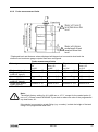
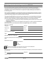
1
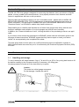
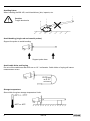
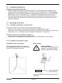
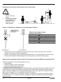
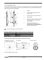
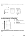
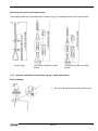
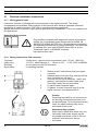
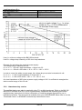
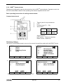
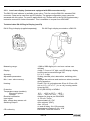
© KROHNE 03/2004
7.02229.33.00
GR
Installation and
Operating Instructions
BM 102
MICROFLEX
T D R Level gauge
2-WIRE
Variable area flowmeters
Vortex flowmeters
Flow controllers
Electromagnetic flowmeters
Ultrasonic flowmeters
Mass flowmeters
Level measuring instruments
Communications technology
Engineering systems & solutions
Switches, counters, displays and recorders
Heat metering
Pressure and temperature
Subject to change without notice.
Table of contents
1
1.1
1.2
1.3
1.3.1
1.3.2
1.3.3
1.3.4
1.3.5
Mechanical installation .....................................................................................................5
Handling and storage ..........................................................................................................5
Installation restrictions .........................................................................................................7
Mounting on the tank ...........................................................................................................7
Installation Instructions: General notes................................................................................7
Installation instructions: nozzle ............................................................................................7
Installation instructions: Gauge - all applications .................................................................9
Specific installation instructions: gauge - liquid applications..............................................12
Specific installation instructions: gauge - solid applications...............................................13
2
2.1
2.1.1
2.1.2
2.1.3
2.2
2.2.1
2.2.2
Electrical connections ....................................................................................................16
Electrical installation instructions .......................................................................................16
Wiring general notes..........................................................................................................16
Wiring connections: DIN connector ...................................................................................16
Wiring connections: M16 terminal box...............................................................................17
Power Supply ....................................................................................................................17
Non-hazardous-duty version .............................................................................................17
Hazardous-duty version.....................................................................................................18
3
3.1
3.2
3.3
3.3.1
3.3.2
3.3.3
3.4
User interface...................................................................................................................19
Power-on and start-up .......................................................................................................19
Available user interfaces ...................................................................................................19
Operator control and display .............................................................................................19
PCSTAR 2 Version 2.01 for Windows : basic installation & operating instructions............19
HART® Communicator......................................................................................................21
Local user display (instruments equipped with DIN connectors only)................................22
Fault clearing .....................................................................................................................23
4
4.1
4.2
4.2.1
4.2.2
4.3
Technical data..................................................................................................................26
Technical data ...................................................................................................................26
BM 102 equipment architecture.........................................................................................29
BM 102 mechanical options (by probe type) .....................................................................29
Probe measurement limits .................................................................................................31
Gauge dimensions.............................................................................................................32
2
BM 102
Device description and range of applications
The BM 102 MICROFLEX level gauge uses the Time Domain Reflectometry (TDR) measuring
principle and two-wire technology for level measurement. It is designed solely for measuring the
distance, level, volume and ullage of liquids, pastes, slurries and powders. It can continue to
measure the level or distance of the top product and total volume in applications with two or more
products.
The level measurement data can be displayed and the gauge configured using either a HART
Handheld Communicator console (HHC) or a PC work station equipped with PCSTAR 2 software
which is supplied as standard with the gauge.
Principal gauge components
BM 102 housing and probes (non-Ex and Ex versions)
1
2
3
4
5
6
7
8
9
10
11
12
13
14
15
with hightemperature
option
with raising
converter
option
Nameplate (see next page for details)
Cable entry (output and power supply) to wiring compartment
Equi-potential bonding system connection (for Ex applications)
Flange (process connection onto tank or other suitable mounting)
Single cable probe
Counterweight (with threaded hole in base for anchoring)
Twin cable probe
Spacer
Chuck (for single cable probes)
Turnbuckle (for twin or single cable probes)
Threaded process connection (e.g. G1, NPT1, …)
Coaxial probe
Extension tube for high temperature applications
Single rod probe
Raising converter: coaxial tube under the process connection (i.e. an inactive length of
the probe) for installations with long nozzles or concrete roofs – for single rod and single
cable probe versions only
BM 102
3
Standard nameplate
*eg. VF030415B0112110110100000. The “type code” is defined in the BM 102 Data Sheet. This
document is available from your local KROHNE Sales office or in the “Download Centre” on
KROHNE’s website http://www.krohne.com/.
Items included with supply
The scope of supply encompasses, in the version as ordered:
• Signal converter with probe in the version ordered. The version is stated on the nameplate.
• PCSTAR 2 computer software for data display and gauge configuration.
Documentation supplied:
Installation & Operating instructions (this manual):
Installation, connection, start-up and safety advice in condensed form, but sufficient for most
applications. This is supplied as a printed document with the device delivered.
Handbook:
Detailed user manual and reference book, including how to configure meter parameters available in
the user menu and how to perform basic maintenance. This is not shipped with the level meter
ordered – it is available in the “Download Centre” on KROHNE’s website http://www.krohne.com/.
Supplementary Installation and Operating Instructions BM 102 KEMA 00 ATEX 1101X:
Supplementary instructions covering devices to be installed and used in hazardous areas. This
document is only supplied with specially approved instruments. This document is available from
your local KROHNE Sales office or on the “Download Centre” on KROHNE’s website
http://www.krohne.com/.
4
BM 102
Product liability and warranty:
The BM 102 TDR level gauge is designed for measuring the distance, level, and volume of liquids,
pastes, slurries, powders and cereal products. It may equally measure level, distance and total
volume in applications with two or more products.
Special codes and regulations apply to its use in hazardous areas : please refer to the BM 102
MICROFLEX KEMA 00 ATEX 1101X Supplementary Installation and Operating Instructions for
further information. This document is available from your local KROHNE Sales office or on the
“Download Centre” on KROHNE’s website http://www.krohne.com/.
Responsibility as to suitability and intended use of these level gauges rests solely with the user.
Improper installation and operation of our level gauges may lead to loss of warranty.
In addition, the "General conditions of sale", forming the basis of the purchasing contract, are applicable.
If you need to return measuring instruments to KROHNE, please note the information given on the
last page of these Instructions. KROHNE regrets that they cannot repair or check your device
unless it is accompanied by the completed form sheet.
The level gauge does not form part of an overfill protection system (as defined for example in
WHG: German water resources act) nor is it concerned by the Pressure Equipment Directive (PED)
97/23/EC.
1
Mechanical installation
1.1
Handling and storage
To carry: the device will weigh between 3 kg or 7 lb and 12 kg or 25 lb. Carry using both hands to lift
the device carefully by the converter housing. If necessary, use lifting gear.
No attempt should be made to lift the instrument by its probe.
Caution:
The probe is a critical gauge component.
Do not damage– Handle with care!!!
BM 102
5
Avoiding blows
When handling the BM 102, avoid hard blows, jolts, impacts, etc.
Caution:
Fragile electronics
Avoid bending (single rod and coaxial probes)
Support the probe to avoid bending.
Support probe here
Avoid cable kinks and fraying
Do not coil the cable less than 400 mm or 16 “ in diameter. Cable kinks or fraying will cause
measurement errors.
Storage temperature
Store within the given storage temperature limits.
6
BM 102
1.2
Installation restrictions
Hazardous-duty systems (Ex, FM,…)
• Refer to the BM 102 MICROFLEX KEMA 00 ATEX 1101X Supplementary Installation and
Operating Instructions supplementary instructions for further information on installing gauges
approved for use in hazardous locations. This document is available from your local KROHNE
Sales office or on the “Download Centre” on KROHNE’s website http://www.krohne.com/.
• Check that the flange, gasket and probe materials are compatible with the product. Read the
information given on the converter nameplate, the flange markings and specifications in the
approval certificates.
1.3
Mounting on the tank
1.3.1 Installation Instructions: General notes
The fitter should give some thought to tank fittings and tank shape.
• Nozzle position in relation to the tank walls and other objects inside the tanks
(Warning : this free area will depend on the probe type selected: refer to later on in this section)
• Type of tank roof , i.e. floating, concrete, integral, etc; and base, i.e. conical, etc.
Whenever working on an installation, remember to:
• Disconnect the power supply before starting work.
• Drain the tank completely before installing the device (not applicable to cable probes).
1.3.2 Installation instructions: nozzle
Threaded process connections
Nozzle height
Recommendation
Do not fit a nozzle longer than its
diameter , especially for single
probes and powder applications
The simplest and most economic way is to
mount the BM 102 directly on the tank with a
GAS or NPT threaded connection.
h ≤ Ød
, where h = nozzle height and
d = nozzle diameter
Contact KROHNE if this relationship cannot be
respected.
BM 102
7
Nozzles extending into tank
Caution:
Do not use nozzles that extend into the tank. This will disturb the electromagnetic
emitted pulse and the measurement.
Installation of two devices
If two devices are to be used on the same tank, these should be mounted a distance of at least 2 m
or 6 ¾ ft away from each other. If not, interferences from the electromagnetic (EM) fields generated
by both instruments may cause measurement errors.
Not applicable to coaxial probes - the outer shell of the probe contains the EM field: no minimum
distance required.
Process connection
For the gauge to make accurate measurements:
• The tank process connection must be level.
• Ensure a good fit with the gauge process connection
• The tank roof should not deform under the weight of the gauge
8
BM 102
Process connection and entry pipe
Caution:
Do not put the nozzle close to the entry pipe. Pouring the product directly onto the
probe will give false readings. Install deflector plate if impossible to distance gauge
from entry pipe.
Stilling wells
Tanks with floating roofs for petro-chemical applications: use a stilling well.
1
Stilling well
2
Tank
3
Floating roof
4
Product (petroleum applications)
5
Well fixed to tank base (no roof
deformation)
6
Sediment
1.3.3 Installation instructions: Gauge - all applications
BM102 gauges are designed to be mounted on a suitable process connection on a tank or sump.
Install the gauge using two people to avoid damaging the probe. Support the housing and the
probe.
BM 102
9
Installation of level meters with single or twin cable probes
1
2
Caution :
Do not over-bend
probe!
Inserting the probe:
hold more than one
metre above the
opening to avoid
cable bending.
Probes: entanglement, straightness and tank bottom clearance
Rigid section length of single
and twin cable probes
Cable diameter
Rigid section length
Single cable
Ø4mm/0.15”
40mm or 1½”
Ø4mm/0.15”
200mm or 8”
Twin cable
Ø4mm/0.15”
40mm or 1½”
•
•
Cable probes must be straight once inserted into the tank. They must also be far from other
objects (e.g. mixers) to avoid entanglement.
In order to maintain the gauge’s operating characteristics, it is recommended to avoid touching
the tank bottom with the counterweights (for cable probes) or probe end (other types).
Objects (discontinuities) inside the tank that influence the probe’s EM (electromagnetic) field
Install the gauge far from protruding objects such as:
• Heating tubes,
• Sudden changes in tank cross-section,
• Tank wall reinforcements and beams,
• Weld lines and dip-stick pipes, etc...
TDR gauges generate electromagnetic (EM) fields when a measurement pulse is emitted. This field
is affected by any nearby discontinuities and these will weaken and potentially block the emitted
pulse. A minimum distance is recommended depending on the probe type to be installed. See the
table on the next page for recommended free space dimensions.
Alternatively, the fitter may use a reference chamber or stilling well. However, the chamber walls
must be smooth (i.e. no visible weld lines), straight and vertical to maintain the pulse strength and
gauge accuracy.
10
BM 102
For clean applications only :
Coaxial (type 3) probes may be used close to or touching objects or walls as the EM field generated
by the probe is contained within the probe’s outer sheath (refer also to the EM field sizes/free area
given in the figures on the next page).
1
Agitator
2
Support beam perpendicular to the
pulse direction
3
Abrupt changes in tank cross section
4
Heating tubes
5
Alternative solution: reference chamber
-electromagnetic field is contained
within chamber
6
Gauge electromagnetic field:
Any intruding metallic object will be
detected in this zone if perpendicular to
the emitted pulse direction.
= Do not fit the gauge near to these objects.
Recommended minimum distance of probe from objects inside the tank
Probe Type
Minimum free space
Single (types 1,2 and 6)
300 mm or 12”
Twin (type 4)
100 mm or 4”
Coaxial (type 3)
0 mm or 0”
Electromagnetic field shape around probe, by type (not to scale)
Single (types 1,2 and 6)
Twin (type 4)
Coaxial (type 3)
No beam angle for any probe type.
BM 102
11
Avoid direct solar radiation
Fit a sunshade on the gauge for open-air installations: this is either supplied on demand by
KROHNE or provided by the customer. The ambient temperature limits of the gauge are given
below.
1.3.4 Specific installation instructions: gauge - liquid applications
Probe bending in agitated products: recommended solutions
1
Agitator
2
Turnbuckle for anchoring probe to
tank bottom
3
Bypass chamber
4
Counterweight (centred on request)
Mounting on a reference vessel or still well is ideal. To ensure that the probe does not come into
contact with the tank wall, the end of the probe should be fixed to the bottom of the chamber or
centred.
12
BM 102
Fastening the probe to the tank bottom
The flexible probe can be fastened with a chuck (ring) or a fastening device to the tank bottom:
Chuck (ring)
Turnbuckle for Ø8 mm cable
probes
Turnbuckle for Ø4 mm cable
probes
1.3.5 Specific installation instructions: gauge - solid applications
False readings:
1
Do not let probe touch the side of the nozzle
BM 102
13
Conical silo nozzles, False readings and traction on the cable probes
Caution
1
High traction forces :
We recommend that the probe should not be
anchored to avoid excessive traction loads on
the cable.
2
Bending and traction:
Position the connection on the roof at ½
radius of the tank and with minimum nozzle
height. This will avoid damage due to bending
and traction during emptying.
Traction forces during emptying cycles for powder applications
Traction load is dependent upon the height and shape of the tank, product particle size & density,
and the rate at which the tank is emptied. The table below gives the load at which cable probes will
support.
Cable maximum design load, traction
Probe
Single cable Ø8 mm or Ø0.3”
Maximum Load
3.5 T or 7700 lb
Traction on cable according to product (approximate value in metric tons)
Probe Length / m (ft)
Probe used
Material
10 (33)
20 (65.5)
24 (79)
Single cable Ø8mm or
Cement
1.0 T or 2200 lb
2.0 T or 4410 lb
2.4 T or 5290 lb
Ø0.3”
Flyash
0.5 T or 1100 lb
1.0 T or 2200 lb
1.2 T or 2650 lb
14
BM 102
Electro static discharge (E.S.D.)
BM 102 non-Ex and Ex gauge electronics are shielded up to 4kV against E.S.D..
Note:
E.S.D. cannot be solved by BM 102 E.S.D. protection. It is the customer’s
responsibility to avoid E.S.D. by grounding the tank, product and probe
installation.
1
Danger of injury
2
The probe may receive an electrostatic
discharge during operation; earth the probe
by pushing it against tank wall with a
suitably isolated tool just before touching it
to avoid receiving a shock.
Earth the entry pipe and product.
Product deposits on the nozzle and probe
Product build-up can occur under the nozzle: this may weaken the pulse. Avoid cavities that permit
the build-up of deposits.
Tank roof deformation
Tank roofs should support loads of at least 3.5 tonnes or 7700lb for gauge installations using
Ø8mm or 0.3” (type 6) single cable probes.
BM 102
15
2
Electrical connections
2.1
Electrical installation instructions
2.1.1 Wiring general notes
Connection to power is effected at the plug connector in the signal converter. Two wiring
compartments are available: DIN connector or M16 terminal box. Observe applicable rules and
regulations for cable connection: VDE 165 or equivalent national regulations.
Always disconnect from power supply before opening wiring compartment. This is not mandatory for
Exi applications.
Hazardous-duty systems
Only certified intrinsically safe equipment may be connected to
the BM 102 in hazardous areas. Please refer to the BM 102
MICROFLEX KEMA 00ATEX1101 X Supplementary Installation
and Operating Instructions for further information. This document
is available from your local KROHNE Sales office or on the
“Download Centre” on KROHNE’s website
http://www.krohne.com/.
2.1.2 Wiring connections: DIN connector
Terminals:
Cable entry:
Shielding:
Signal cable:
3 poles and 1 x ground. Wire cross-section: max. 1.5 mm² (AWG 16)
1 x PG11, cable diameter: 8 … 10 mm or 0.31” … 0.39”, IP 65 or NEMA4
do not connect to the DIN connector.
no shielding required
1
2
3
4
5
Detach screw P and remove plug from signal
converter.
Separate part N from part R by inserting the flat
tip of a screwdriver into gap F.
Connect current loop to terminals 1 and 2 (any
polarity). Use ferrules to protect cable ends.
Terminals 3 and E are not connected.
Fit parts N and R together again.
Fit gasket, re-insert connector plug R on the
signal converter, and replace screw P.
Caution
Grounding terminal E is not connected to
the housing of the signal converter or to
the device flange. To avoid ground current
loops, the cable shielding may not be
connected at both ends.
Hazardous-duty systems
When used in hazardous areas, only one
intrinsically safe power supply may be
connected to terminals 1 and 2. Ground
terminal E and terminal 3 are not
connected.
16
BM 102
2.1.3 Wiring connections: M16 terminal box
Power terminals:
Cable entry:
Shielding:
Wire cross-section: max. 1.5 mm² (AWG 16)
1 x M16 x 1.5, cable diameter: 3.5 … 8 mm or 0.14” … 0.31”, IP65 or
NEMA4.
For USA: ½” NPT conduit connection
Do not connect shielding to the terminal compartment.
Hazardous-duty systems
When used in hazardous areas, only one intrinsically safe power supply may be
connected to terminals 1 and 2. Ground terminal E is not to be connected.
Caution
Ground terminal, E, is not connected to the signal converter housing or to the device
flange. To avoid ground current loops, the cable shielding may not be connected at
both ends.
1
2
3
2.2
Detach the 4 screws, T, and remove cover from terminal
compartment.
Connect the cable ends, fitted with ferrules, to the power
terminal, U (not polarity sensitive).
Shut the terminal compartment.
Power Supply
2.2.1 Non-hazardous-duty version
Power supply
Rated voltage:
Max. voltage
(Uinput max):
Min. voltage
(Uinput min):
24 V DC
35 V DC
’Ex’ = 28 V DC
dependent on
load impedance,
see graph below
A supply voltage above 35 V DC can cause irreparable damage to the signal
converter. Also, power supply voltages above the specified max. values and below
the specified min. values can lead to faulty measurements or to a device reset.
BM 102
17
Load impedance Rloop
Loop resistance, Rloop
Min. Rloop
Max. Rloop
RHART resistance for HART® communication
RHART + Rcable + Rammeter
0 ohms
750 ohms
250 ohms (recommended)
Line A = minimum voltage at the BM 102 terminals
Line B = voltage drop caused by a 250 ohm loop resistance
Example for calculating the required power supply:
The voltage drop is tested at 22 mA.
U power min. 22 = 22 mA x load impedance + Uinput min. 22
U power min. 22 = 22 mA x 250 ohms + 10 V = 5.5 V + 10 V = 15.5 V
In order to cover the whole current range, the voltage drop must also be tested at 4 mA:
U power min. 4 = 4 mA x load impedance + Uinput min. 4
U power min. 4 = 4 mA x 250 ohms + 18 V = 1 V + 18 V = 19 V
At a load impedance of 250 ohms a power supply voltage of 19 V is sufficient to energize the
device current range of 4 to 20 mA.
2.2.2 Hazardous-duty version
The certified device may only be used with other ’Ex’ certified equipment. Refer to the BM 102
MICROFLEX KEMA 00 ATEX 1101X Supplementary Installation and Operating Instructions
supplementary instructions for further information on installing gauges approved for use in
hazardous locations. This document is available from your local KROHNE Sales office or on the
“Download Centre” on KROHNE’s website http://www.krohne.com/.
18
BM 102
3
User interface
3.1
Power-on and start-up
The BM 102 is pre-configured in accordance to customer order specifications and measurements
can be made immediately. A warm-up time of less than 23 seconds should be allowed for once
connected and the power is switched on.
3.2
Available user interfaces
Measurements may be taken using either:
• PC STAR 2 software
•
HART® Handheld Communicator (HHC)
•
DA 06 local indicator
3.3
Included as standard with the instrument. The
basic installation & operating instructions are
presented in section 3.3.1 (requires PC
workstation).
Sold separately. Automatic recognition of the
instrument when connected. A list of HHCaccessible parameters is given in the BM 102
Handbook.
Sold as an option for devices equipped with DIN
connectors. For displaying readings only. Refer to
section 3.3.3 for technical data.
Operator control and display
You can configure the device by way of the PC-STAR 2 software or the HHC. Refer to the BM 102
Handbook, section 3.3 for more details. This document is available from your local KROHNE Sales
office or in the “Download Centre” on KROHNE’s website http://www.krohne.com/.
3.3.1 PCSTAR 2 Version 2.01 for Windows : basic installation & operating instructions
Software description
PC STAR 2 is a Windows program that permits clear and concise display of data and configuration
of the BM 102 from a remote location. The program is available in English, German or French.
PC-STAR 2 system requirements
•
•
•
•
•
•
•
PC with at least 486 processor 75 MHz, recommended: Pentium 120 MHz or higher
Microsoft Windows 9x, Me, 2000, NT and XP
Min. 16 MB main memory (RAM)
Min. 3 MB available hard disk storage
3 ½ “ Floppy disk drive
Mouse or other pointing device
Serial RS232 port
BM 102
19
Installing and connecting the PCSTAR 2 software
1.
Connect the HART® adapter (not included in supply) through a load impedance of 350 ohms
maximum (for hazardous-duty purposes, fix to the non-intrinsically safe side of the repeater
power supply unit) and plug it into a serial interface on your PC. The repeater power supply
®
unit must have HART capability.
2.
Installing the program: Access the files on the floppy disk supplied with the instrument and
execute the file "setup.exe" and follow the instructions on the screen.
3.
Running the program: once the program is installed, execute the program.
4.
Define device interface: type F4 or left-click on “F4-Serial” at the bottom of the screen - to
define the interface to which the device is to be connected.
Serial Port
BM102 Address
Device Identifier
Initial baud rate
RTS state
5.
6.
•
•
•
•
•
•
•
The serial port allows the user to select a free serial port (COM 1 to 4) on
the computer.
Type the “Address” that you have given a gauge (a value between 0 and 15)
and press ENTER or OK. This will select the required device. If you are in a
point to point network leave the box at its default value (-1).
Device Identifier refers to the “Device number” given in User Function No.
1.4.4.
Transmission rate of data. Has a default value of 1200 bd. Trials should be
run to find the optimum operating conditions.
The RTS state depends on the type of RS232 converter used. For
RS232<>HARTTM(i.e. VIATOR from MACTEK) use inversed RTS state.
On-line connection with the gauge: Press F2 or left-click on “F2-Connection” to set up the
connection with the device - the configuration parameters are automatically loaded into the
gauge.
After the connection has been established, the following screen is shown. This will show the
current status of the tank. No further configuration should be necessary. The following functions
are available on the screen and are discussed further in the BM 102 Handbook*:
F2 – Device configuration: a summary of the parameters are given on the next page,
F7 – Oscilloscope function: have all reflections occurring at the probe displayed,
F11 – Dynamic/on-line device configuration,
F4 – View and record all information during operation,
F6 – Trend: observe the level trend since start of the program,
F8 – Marker: the status of the device
And F10 – make printouts (screen shots).
Special note: F8 – Markers Menu
Displays a real-time evolving graph of error markers which are either displayed as active (value 1) or
inactive (value 0).
Refer to section 3.4 “Fault clearing” for corrective procedures when the markers shown above are
active.
*This document is available from your local KROHNE Sales office or on the “Download Centre” on
KROHNE’s website http://www.krohne.com/.
20
BM 102
®
3.3.2 HART Communicator
Display and configuration can also be carried out via a HART® communicator. Operator control via
this unit is described in detail in the operating instructions supplied with the HHC.
Basic operating instructions for taking measurements
Communicator layout
1
2
3
4
Two-pin jack for loop connectors
LCD
Function keys (F1 … F4)
Action keys
On/off
LEFT
Arrow
UP
Arrow
DOWN
Arrow
n/a
RIGHT
Arrow
Other functions:LEFT Arrow: Previous menu key
RIGHT Arrow: Select key
Displaying readings
Use the UP and DOWN arrows to move to the correct line and then select with the RIGHT Arrow.
1
HART Communicator
1
Offline
2 →
Online
3
Frequency Device
4
Utility
F1
3
F2
F3
Main menu
2
BM102:00000 01
Online
1 →
<Process Var.>
2
<Config./Test>
3
<Access/Rights>
4
<Watch status>
5
<HART Variables>
SAVE
F1
F2
F3
F4
Online menu
4
BM102:00000 01
♥
<Measurements>
1 →
<Lvl> 878.00 mm
2
<Dist> 121.00 mm
F4
BM102:00000 01
<Process Var.>
1 →
<Measurements>
2
<Input/Outputs>
SAVE
HOME
F1
F2
F3
F4
Measurement & input and output functions menu
BM 102
HELP
SAVE
HOME
F1
F2
F3
F4
Measurement display function
21
3.3.3 Local user display (instruments equipped with DIN connectors only)
The BM 102 local indicator is available as an option. This fits onto the BM 102’s standard DIN
connector. Data can be read from an LED display. The gauge configuration menu cannot be
accessed with this option. For non-Ex applications only. Please refer to the DA 06 Supplementary
instruction manual for further information. This is available on request from KROHNE.
Technical data: DA 06 Plug-in Display (non-Ex)
DA 06 Plug-in display (supplied separately)
Measuring range:
Display:
Accuracy:
Adjustable parameters:
Min. / max. value memory:
Housing:
Protection:
Temperature range (ambient)
Electronic system:
Storage:
Electrical connection:
Input signal
Max. voltage drop across unit
Switching output1
CE conformity
22
DA 06 Plug-in display mounted on a BM 102
-1999 to 9999 digits (min. and max. values user
defined)
4-digit, 7.6 mm or 0.3” high, red LED display, display
housing can be turned through 330°
0.1 % +/- 1 digit
Scaling, decimal point, attenuation, switching point,
delay
Displays the minimum and maximum values recorded
during operation.
Plastic, PA 6.6 / polycarbonate 47mm X 47mm x 68
mm or 1.9” x 1.9” x 2.7” (h x w x d), housing can be
turned by 300°
IP 65 (EN 60529) or NEMA4
0°C … +60°C or 32°F … 140°F
-30°C … +80°C or -22°F … 176°F
Adapter for plug as per DIN 43650
4…20 mA / 2-wire
Approximately 6 V DC
open collector (PNP),
max. 125 mA,
on and off delay: 0 to 100 seconds,
temperature influence: 0.1% / 10 K
EN 50081-1 and EN 50082-2
BM 102
3.4
Fault clearing
Event
Error messages
“Tank full” status marker on*,
reading frozen at max. or min.
value
“Tank empty” status marker
on*, reading frozen at max. or
min. value
“Tank full” and “Level lost”
status marker on*, reading
frozen at max. or min. value
“Level lost” status marker on*,
reading is frozen
“Reference not found” status
marker on*
“Level lost” and
“Reference not found” status
markers on*, reading frozen
Fault
Action
No fault. The level has
reached (and possibly risen
above) the top configured
measurement limit and is
either displaying the maximum
(when measuring level) or
minimum (when measuring
distance) output.
No fault. The level has entered
the gauge’s bottom dead zone
and can no longer detect a
return signal. Either the
maximum (when measuring
distance) or minimum (when
measuring level) output is
displayed.
The level has entered the
gauge’s top dead zone and
can no longer detect a return
signal.
The instrument has lost the
level signal, has searched but
not yet found the return pulse.
This may occur if the pulse
has dropped below the
threshold. Parasite signals
from the flange or obstructions
in the tank may render the
gauge unable to identify the
correct signal.
None. Measurements should
be normal once the level is in
the configured measurement
range.
Occurs when there is a
problem with the time base on
the HF board.
The probe has received an
electrostatic discharge.
None. Measurements should
be normal once the level is in
the configured measurement
range.
Empty the tank below the top
measurement range limit and
check the measurement.
Empty tank below maximum
level or fill tank above the
minimum level and check the
measurement.
If the signal is not detected
then modify the control
threshold manually as shown
in sections 3.5.2 and 8.4.2 of
the BM 102 Handbook using
the oscilloscope (F7) and
dynamic configuration (F11)
windows in PCSTAR 2.
Please contact your local
KROHNE Service Centre**.
The gauge will search for the
level again and resume
readings. If the reading
remains frozen then the signal
converter may have been
damaged by ESD and may
need replacing. Please
contact your local KROHNE
Service Centre**.
*Gauge connected to PC-STAR 2 software or HART Handheld Controller (HHC) with Marker
status window (F8) or “Watch status” (Menu 4.0) list displayed respectively.
**A list of contact details for every KROHNE service centre is supplied on the last page of these
instructions.
BM 102
23
Event
“Flange not found” status
marker on*
“Delay out of limits”
status marker on*,
reading is frozen.
“Negative voltage error”
status marker on*
“VC01 voltage error ”
status marker on*
“VC02 voltage error”
status marker on*
“Reprogramming FPGA”
status marker on*
General operation
The BM 102 indicates an
incorrect level value.
Instrument is not
accurate when there are
two or more phases in
the tank.
Fault
The signal converter has been
incorrectly configured to
measure with a cable or rod
probe when it is equipped with
a coaxial probe. This may also
due to installation on a long
nozzle which has the effect of
attenuating the flange pulse.
The emitted pulse has not
been detected. The gauge will
not work until it has been
found.
Occurs when there is a
problem with the time base on
the HF board.
Action
Contact KROHNE for the corrective
procedure**.
The BM 102 measures a nonvalid reflection.
Check the tank for obstructions and
verify that the probe is clean. When
the indicated level is close to the
nozzle, increase the detection
delay and the dead zone with the
same ratio or increase the
threshold level if the full
measurement range is essential.
In any case, use the PCSTAR 2
oscilloscope function,F7, to
visualise and to analyse the
application. The threshold level
must be adjusted so that it masks
the disturbances.
Very large pulses along the
measurement signal (same
amplitude as the emitted pulse) can
be caused by a probe touching the
nozzle or tank side (section 1.3.5)
Contact KROHNE** for the
corrective procedure or refer to the
Service Manual.
Check that Factory Menu function
1.1.3: Application Type is set to “2
liquids, 1 level”.
Check also that there is a layer of
more than 100 mm of top product
above the bottom product.
The instrument may be
incorrectly configured for this
type of application i.e. it is
measuring the interface
instead of the level.
The signal converter may need
replacing. Please contact your local
KROHNE Service Centre**.
Please contact your local KROHNE
Service Centre**.
*Gauge connected to PC-STAR 2 software or HART Handheld Controller (HHC) with Marker
status window (F8) or “Watch status” list (Menu 4.0) displayed respectively.
**KROHNE service centre contact details are supplied on the last page of these instructions.
24
BM 102
Event
Fault
Electrical Connections and Communication Output
Current Output value
No power supply
< 4 mA.
Connection of the device is
incorrect.
The calibration of the current
output is incorrect.
Reads 22 mA.
An error has occurred.
The device is in its start-up
phase.
The value at the current
output does not correspond
to the value at the display
®
(PC STAR 2 or HART
communicator).
The current output settings
are incorrect.
Data communication via the
digital interface is not
working.
The BM 102 is in its start up
phase, wait 50 seconds and
try again.
The communication
parameters of the computer
are set incorrectly.
Bad connection to the
interface.
Current output value is < 4
mA.
Current output value is = 22
mA
Action
Check the power supply.
Check the connection between the
device and the power supply.
Execute the calibration if you have
authorized access or contact
KROHNE Service Centre**.
This happens in case the range 420 mA / error 22 mA is selected.
Check the status of the device by
selecting the marker window (F8)
or enter the Watch status (4.0)
®
menu of the HART communicator.
Wait 50 seconds. If the current
value drops to a value between 4
and 20 mA, and goes immediately
back to 22 mA, contact your
KROHNE Service Centre**.
Check the current loop and the
connections. Configure output as
described in Sect. 3.3.3 (user submenu 1.3) of the BM 102
Handbook* - also try adjusting the
threshold using F11-Dynamic
Configuration function (PCSTAR 2)
or menu 2.1.5.1.0 – Threshold
(HHC).
Check computer setting
(address/device number).
Check connection.
Contact your KROHNE Service
Centre**.
If problem persists then contact
your KROHNE Service Centre**.
*This document is available from your local KROHNE Sales office or on the “Download Centre” on
KROHNE’s website http://www.krohne.com/.
** KROHNE service centre contact details are supplied on the last page of these instructions.
BM 102
25
4
Technical data
4.1
Technical data
Application
Range of applications
Continuous level measurement of liquids, solids and powders
Function and system design
Measuring principle
Equipment architecture
Time domain reflectometry using a direct mode of measurement
See section 4.2
Input
Measured variable
Measurement range
Blocking Distance
(dead zone)
Output
Analogue
Digital
Digital, Ex ia
Signal on alarm
Distance (between the reference point – gauge flange facing –
and the product surface), level, liquid interface & volume
Variable according to probe type, see Equipment architecture,
section 4.2.1 Minimum tank height = 0.15 m or 0.5 ft.
Variable according to probe type, see probe measurement limits,
section 4.2.2
4 … 20 mA, passive output
Load
Passive outputs
750 Ω maximum
Error signal
22 mA
Resolution
± 3 µA
®
HART , passive output
®
HART , passive intrinsically-safe output
®
Status markers via PC STAR 2 or HART controller (HHC)
Performance characteristics
Reference operating conditions
Ambient temperature
+20°C ± 5°C or +68°F ± 9°F
Ambient air pressure
1013 mbar abs. ± 20 mbar or 14.69 psig ± 0.29 psi
Relative air humidity
60% ± 15%
Reference target
- coaxial probe :
water surface
- single probe :
Ø 0.8 m or Ø 31.5 in. metal plate
- twin probe :
metal block “short circuit”
Free space diameter
> 300 mm or > 11.81” *
Distance to obstruction
> 1 m or > 3.3 ft.
Accuracy
Level measurement
Liquids when probe length, L ≤ 15 m or 50 ft.
± 15 mm or 0.6” outside the dead zone
Optional: ± 5 mm or 0.2”
Liquids when probe length, L > 15 m or 50 ft.
± 15 mm or 0.6” ± 0.1% of the measured distance
Optional: ± 0.05% of the measured distance
Solids (powders)
± 20 mm or 0.8”
with 4 … 20 mA current output
± 0.01% of the measured distance
* not for coaxial probe.
26
BM 102
Repeatability
Hysteresis
Resolution
Transient recovery time
± 2 mm or 0.08”
none
± 1 mm or 0.04”
The transient recovery time to 1% deviation from the final value
amounts to approximately 4.6 times the programmed time
constant. However, the transient recovery time may differ if
changes in level are very rapid.
Start-up time
≤ 23 seconds
Long term drift
This is within the specified error of measurement. Allow for
thermal expansion coefficient in the case of liquids. Organic
liquids: 0.15%/K
Influence of ambient temperature
®
current output
HART : typically 70 ppm/K
measured value
25 ppm approx. (max. deviation over total measurement range)
atmosphere
-1 ppm/K (above the liquid product)
digital
No influence on measured value due to regular self-calibration
Environment
Ambient temperature
Storage temperature
Protection
Shock resistance
Vibration endurance limit
-30°C … +60°C or -20°F … +140°F***
-40°C … +80°C or -40°F … +176°F
IP 65 / NEMA 4 – 4X
The device withstands the impact test in conformity with EN
61010, Section 8.2 with 0.5 J energy.
IEC 68-2-6 and prEN 50178
(10-57Hz: 0.075 mm / 57-150 Hz: 1 G).
Power supply
Standard
Hazardous-duty (Ex, FM, …)
Range
24 V DC,
≤ 28 V DC
18 … 35 V DC
Process
Process temperature, product
Process temperature, flange
Process pressure,
standard
-30°C … +200°C or -22°F … +392°F * **
-30°C … +90°C or -22°F … +194°F*, option +200°C or 390°F**
-1 … 16 bar abs. or -14.5 … 232 psig***;
max. 40 bar or 580 psig at 20°C or 45°F***
Dielectric constant εr of product measured: probe type limits
Coaxial (type 3)
εr ≥ 1.4
Twin probe (type 4)
εr ≥ 1.8
Single probes (types 1, 2 & 6) εr ≥ 2.1
Human interface
Communication, standard
Operator control and data display via PC using PCSTAR 2
software or HART® handheld communicator
Point-to-point
1 gauge connected to a PC or HHC
Multi-drop
Up to 5 gauges connected to a PC or HHC
*
see BM 102 MICROFLEX KEMA 00ATEX1101X Supplementary Installation and Operating
Instructions for Ex values (temperature classes)
** higher or lower temperatures on request (non-Ex)
*** Subject to the process temperature and the mechanical properties of the process connection
BM 102
27
Construction materials
Housing
Probe
Gasket
Spacers (on twin probes)
Aluminium with epoxy coating
Refer to section 4.2.1: BM 102 mechanical options
Viton, optionally Kalrez 6375
Refer to section 4.2.1: BM 102 mechanical options
Weight
Housing
Single rod Ø8mm or Ø0.3”
Single cable Ø4mm or Ø0.15”
Twin cable Ø4mm or Ø0.15”
Single cable Ø8mm or Ø0.3”
Coaxial Ø28mm or Ø1.1”
2 kg or 4.4 lb
0.41 kg/m or 0.28 lb/ft
0,12 kg/m or 0.08 lb/ft
0.24 kg/m or 0.16 lb/ft
0.41 kg/m or 0.28 lb/ft
1,3 kg/m or 0.87 lb/ft
Standards
Electromagnetic compatibility
directives followed for EU
countries
Other EU directives
The level gauge satisfies the protection requirements of :
Electromagnetic compatibility
Directive 89/336/EEC in conjunction with EN 61326-1(A1&A2)
and EN 61000-6-2 standards. It also respects the NAMUR NE
21/98 standard. Protection against EMC emissions is only
guaranteed when the device is used in metal tanks (except when
the device is equipped with coaxial probes).
Low voltage electrical equipment
Directive 73/23/EEC modified by Directive 93/68/EEC (art.13) in
conjunction with the EN 61010-1 standard.
ATEX*
Directive 94/9/EC in conjunction with EN 50014, EN 50020 and
EN 50284 standards.
Refer to the BM 102 MICROFLEX KEMA 00 ATEX 1101X
Supplementary Installation and Operating Instructions for further
information.
Approvals
ATEX*
KEMA 00 ATEX 1101 X
Factory Mutual Research*
Project ID 3009543
CSA*
Project 1183965 (Edition 1)
(KEMA: 2007223.00)
II 1 G or II 1/2 D T 100 °C
EEx ia IIC T6 … T3 or EEx ia IIB T6 … T3
FM Class I, Div. 1, Gr. A, B, C, D and Class II, III, Gr. E, F, G
FM Class I Zone 0 AEx ia IIC T4 resp. AEx ia IIC T6
Class I, Div. A, B, C and D: Class II, Div. E, F and G; Class III;
Ambient temperature -30°C … +60°C or -20°F … +140°F; max.
product pressure 4000 kPa (580 psi).
* only approved if requested in customer order.
28
BM 102
BM 102
SS 316 / 316L
Probe material
Liquid
* gauge with flange connection
SS 316L
Hastelloy C276
DN50 PN 25/40
2” ANSI 150 lbs
2” G / 2” NPT**
1.8
Ø200 mm
or Ø8”
≤ 24 m or 79 ft.
Minimum process DN50 PN 25/40
connection
2” ANSI 150 lbs
1” G / 1” NPT
1.4
Ø0 mm
or Ø0 “
Free area (no
obstructions or
discontinuities)
Minimum
dielectric constant, εr
≤ 6 m or 20 ft.
Range, max.
Level
SS 316 / 316L
DN50 PN 25/40
2” ANSI 150 lbs
1½” G / 1½” NPT
2.1
Ø600 mm
or Ø4”
≤ 24 m or 79 ft.
Single flexible cable
with counterweight.
Single cable Ø8 mm
or 0.3” (Type 6)
*** on request
Powder
Hastelloy C276
PVDF coated (non-Ex)*
PVC coated (non-Ex)*
SS 316L
DN50 PN 25/40
2” ANSI 150 lbs
1” G / 1” NPT
2.1
Ø600 mm
or Ø24”
≤ 3 m or 10 ft.**
Single rigid rod.
Single rod Ø8 mm
or 0.3” (Type 1)
** higher on request
SS 316 / 316L
Hastelloy C22
SS 316 FEP coated
DN50 PN 25/40
2” ANSI 150 lbs
1” G / 1” NPT
2.1
Ø600 mm
or Ø24”
≤ 24 m or 79 ft.
Single inner conductor Two flexible SS316 Single flexible cable
with protective tube. cables with spacers with countrerweight.
interspersed along its
length, with short
circuit and
counterweight.
Description
Single cable Ø4 mm
or 0.15” (Type 2)
Coaxial Øext. 28 mm Twin cable Ø4 mm
or 0.15” (Type 4)
or 1.1” (Type 3)
Probe
(Type code)
Liquid / Liquid Gas applications
4.2
4.2.1 BM 102 mechanical options (by probe type)
BM 102 equipment architecture
29
30
BM 102
** higher on request
None
Counterweight
(dimensions in
mm)
Gauge
illiustration
PTFE (if length
> 1.5 m or 5 ft).
Spacer material
*** on request
Ø45 x 60 (316L)
Turnbuckle (316L)
FEP moulded onto
the cable.
Coaxial Øext. 28 mm Twin cable Ø4 mm
or 1.1” (Type 3)
or 0.15” (Type 4)
Probe
(Type code)
Ø25 x 100 (316L)
Ø25 x 100 (HC22)
Ø25 x 100 (HC276)
Chuck (316L)
Turnbuckle (316L)
No spacer.
Single cable Ø4 mm
or 0.15” (Type 2)
Liquid / Liquid Gas applications
None
No spacer.
Single rod Ø8 mm
or 0.3” (Type 1)
Powder
Ø12 x 100 (316L),
where L1 > 10m/33ft
Ø45 x 245 (316L),
where L1 < 10m/33ft
Turnbuckle (316L)***
Without***
No spacer.
Single cable Ø8 mm
or 0.3” (Type 6)
4.2.2 Probe measurement limits
* Displayed level and distance values displayed will depend on how and at what level the
minimum and maximum gauge outputs have been configured.
Probe type
Probe measurement limits
Top dead zone, Bottom dead
A1
zone, A2
εr=80*
εr=80*
300mm or 12”
20mm or 0.8”
300mm or 12”
20mm or 0.8”
Top dead zone,
A1
εr=2.4*
400mm or 15¾”
400mm or 15¾”
Single rod (type 1)
Single cable Ø4mm
or Ø0.15” (type 2)
Coaxial (type 3)
0mm or 0”
10mm or 0.4”
0mm or 0”
Twin cable Ø4mm
150mm or 6”
20mm or 0.8”
300mm or 12”
or Ø0.15” (type 4)
Single cable Ø8mm
300mm or 12”
20mm or 0.8”
400mm or 15¾”
or Ø3” (type 6)
* The dielectric constant εr of water is 80. The dielectric constant εr of oil is 2.4.
Bottom dead
zone, A2
εr=2.4*
100mm or 4”
100mm or 4”
100mm or 4”
100mm or 4”
100mm or 4”
Note:
The default factory setting for A1 is 400 mm or 15 ¾”, except for the coaxial probe (0
mm or 0”). Please consult KROHNE if you wish to reduce the size of the programmed
top dead zone, A1.
If the device is mounted on a tank fitting (e.g. a nozzle), include the height of the tank
fitting in the programmed dead zone.
BM 102
31
4.3
Gauge dimensions
The drawing below illustrates standard gauge configurations and overall dimensions.
Housing
Standard,
M16 terminal box* with
flange
Standard, DIN
connector** with
threaded
connection
High
temperature
version
With
inactive
length***
Probe
3: Coaxial
Ø 28 (1.1)
4: Twin cable
Ø 4 (0.15)
2: Single cable
Ø 4 (0.15)
1: Single rod
Ø 8 (0.3)
6: Single cable
Ø 8 (0.3)
Standard counterweight
None
Ø45x60
Ø25x100
None
Ø12x100 (ؽx4)**** or
(Ø1¾x2½ )
(Ø1x4)
Ø45x245 (ؽx9¾)*****
Size of threaded hole in base of counterweight for anchoring
None
M8
M8
None
M8
Dimensions in mm (inches)
*with a cable fitting M16X1.5 Ø3.5 … Ø8
**with a cable fitting PG11 Ø8…Ø10 DIN43650-A
*** the inactive length (i.e. a non-active extension at the top of the probe) may be supplied with
the following standard lengths : 100 mm or 4”, 200 mm or 8”, 300 mm or 12”, 400 mm or 16”, 500
mm or 20” and 1 m or 40“ – for single cable and single rod probe versions only.
**** where L > 10m or > 33ft
***** where L < 10m or < 33ft
L = ordered probe length
32
BM 102
Returning a device for testing or repair to KROHNE
Your instrument has been carefully manufactured and tested. If installed and operated in
accordance with these operating instructions, it will rarely present any problems. Should you
nevertheless need to return an instrument for inspection or repair, please pay strict attention to
the following points.
Due to statutory regulations on environmental protection and safeguarding the health and safety
of our personnel, KROHNE may only handle, test and repair returned devices that have been in
contact with products without risk to personnel and environment.
This means that KROHNE can only service your instrument if it is accompanied by the following
certificate confirming that the instrument is safe to handle. If the instrument has been operated
with toxic, caustic, flammable or water-endangering products, you are kindly requested:
• to check and ensure, if necessary by rinsing or neutralizing, that all cavities are free from such
dangerous substances,
• to enclose a certificate with the level gauge conforming that it is safe to handle and stating the
product used.
We cannot service your instrument unless accompanied by such a certificate.
Specimen certificate
Company:
Address:
Department:
Name:
Tel. No.:
Fax No.:
The enclosed level gauge
Type:
KROHNE Order No. or Serial No.:
has been operated with the following process
liquid:
Because this liquid is
water-hazardous
toxic
caustic
flammable
we have
checked that all cavities in the instrument are free from such substances
flushed out and neutralized all cavities in the device
We confirm that there is no risk to humans or environment through any residual liquid contained in
the instrument.
Date:
Signature:
Company stamp:
BM 102
33