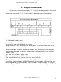
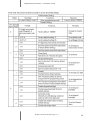
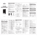
1
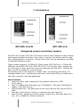
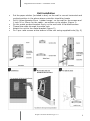
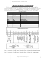
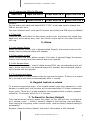
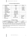
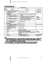
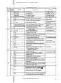
Installation Manual INTEGRATED ACCESS CONTROLERS PROXIMITY CARD READERS KZC-800-U/H KZC-800-M KZC-900-U/H VERSION 1.0 Integrated Access Controller – Installation manual 1. Introduction KZC-800-U/H/M KZC-900-U/H Integrated access controllers/readers The KZC-800-U/H/M i KZC-900-U/H access control units realize the card reading and keypad operation functions, lock, alarm, ring bell, exit button and the magnetic contact switch on the door. Those units can be use as standalone controller or standard Wiegand reader. These models supports 13.56MHz IC Mifare cards (KZC-800-M) or 125KHz EM, HID Prox cards (KZC-800-U/H i KZC-900-U/H ). It controls 1 door, supports up to 2000 users in total, each user have one card and one PIN (PIN - 1234 as default, should be change for normal using). The access control unit supports 1 master code, one manager add card, one manager delete card, 1 anti-duress card and 1 anti-duress PIN, providing users with easy operation and safe guarantee. Main Features Aluminum alloy case, waterproof, fully potted, confirms to IP65 Touch panel Built-in 125KHz (EM, HID card) and 13.56MHz(IC, CPU card, ISO14443A) reader ( KZC-800-M only) Digital backlit key. The back light can be set to Normal ON, Normal OFF or Auto. With door bell function, build-in or external door bell optional. Multi-function, operating as slave reader, single door, anti-pass back function, etc., suitable for various occasions. All rights reserved © AAT Holding sp. z o.o. 2 Integrated Access Controller – Installation manual Detail features 2 000 users with card and PIN 3 identification modes: card, PIN, card + PIN Read both 125KHz EM & HID card PIN length: 4-8 digits Pulse mode, Toggle mode of lock relay Wiegand 26-37 input & output Can be worked as controller or reader One relay output for door opening, inputs for door status detecting and open door by button Card block enrollment Manager cards for adding or deleting card user easily Very low power consumption (35mA) Backlight keypad Light and sound of keypad can be set on/off Support door bell connection Built in light dependent resistor (LDR) for anti tamper Built in buzzer Red, yellow and green LED display the working status 12-24V DC Technical specifications Operating Voltage User Capacity 12~24V DC 2 000 with card and PIN (1234 - default PIN) Keypad Card Type Card Reading Distance Recommended supply power Idle Current Lock Output Load Alarm Output Load Bell Output Load Operating Temperature Operating Humidity Environment Adjustable Door Relay time Adjustable Alarm Time Wiegand Interface Wiring Connections 12 keys, 3 x 4 digits and 2 x 6 digits (KZ-900) EM & HID 125 KHz card, Mifare (13,56 MHz) 3~6 cm (125 kHz), 2~5 cm (13,56 MHz), 2A (controller unit plus electric lock) ≤35mA Maximum 1A Maximum 1A Maximum 1A -20~60℃ 0%~95% (non condensing) Confirms to IP65 1~99 seconds, 3s - factory default 0~3 minutes, 1 min. - factory default Wiegand 26~37 input & output Electric lock, External alarm, Door status (NC), Exit button (NO), Bell Dimensions: KZC-800-U/H/M KZC-900-U/H 125 x 83 x 22 mm (HxWxD) 159 x 43 x 22 mm (HxWxD) All rights reserved © AAT Holding sp. z o.o. 3 Integrated Access Controller – Installation manual Unit installation Put the paper sticker (included in box) on the wall in correct horizontal and vertical position in the place where controller should be locate Drill 4 holes diameter 6mm(rubber bungs)on the wall for the screws and 1 hole 30 or 22mm for the cable - as written on the sticker (figure 1) Fix the metal product bracket firmly on the wall with 4 flat head screws Thread the cable through the cable hole Attach the unit to the metal bracket (figure 2) Fix 2 pcs. safe screws at the bottom of the unit using supplied tools (fig. 3) All rights reserved © AAT Holding sp. z o.o. 4 Integrated Access Controller – Installation manual 2. Access standalone controller mode In this mode unit works as standalone controller. This is factory default mode (command 7-1-1-#). It’s possible to connect additional reader for two way control and activate anti-passback feature. To change unit for Wiegand reader mode please use command: 7-1-0-# (this mode is describe on next pages) . Wiring diagram Color Function Description Light green BELL_A Bell control output Pink BELL_B Bell control output Red +12V Supply power input (12~24V DC) Black GND Supply power input (12~24V DC) Green White D0 D1 Wiegand input Wiegand input Brown D_IN Door contact input Yellow Open Request to Exit Button input Blue NO Lock relay output Purple COM Lock relay output Orange NC Lock relay output Gray ALARM Alarm output Lock A connection - for NC type - Normally Close - locked without supply power Lock B connection - for NO type - Normally Open - locked with supply power All rights reserved © AAT Holding sp. z o.o. 5 Integrated Access Controller – Installation manual Installation and Wiring Diagram Principle of Electronic Lock The relay will close contact to unlock the lock and will release after unlocking COM: common, relay contact NC: normal close, normally keep closed to COM NO: normal open, normally keep opened to COM Wiring of electronic lock Connect COM and GND, connect two ends of electronic lock with +12V and NO(or NC), complete the circuit. Type A electronic lock: Fail Secure lock (Unlock when power on), such as Electronic Controlling Lock, smart lock etc. Type B electronic lock: Fail Safe lock (Unlock when power off), such as Electromagnetic Lock, Electronic Bolt Lock, etc. 1N4004 Diode: prevent high voltage to two ends of the electronic lock while the contact of relay disconnect . Without diode, there will be high voltage pulse interference to circuits and the life time of the relay will be greatly reduced. Principle of Alarm Connector The field-effect tube will be conducted when alarm is activated; It will be not conducted when alarm is removed Principle of Door Bell Connector Each press of door bell button, contact of relay in BELL_A and BELL_B will close contact for 200mS then release. All rights reserved © AAT Holding sp. z o.o. 6 Integrated Access Controller – Installation manual 3. Manager Card operation 3.1 Add user card(s) Read manager add card Read User card Read manager add card Cards can be added continuously. 3.2 Delete user card(s) Read manager delete card Read User card Read manager delete card Cards can be deleted continuously. 4. User Operation 4.1 To unlock the lock by one card Read valid card once Lock will be unlocked 4.2 To unlock the lock for card and PIN users Read valid card once Input 4-6 digits PIN # Lock will be unlocked 4.3 To unlock the lock for card or PIN users Read valid card once, or Input 4-6 digits PIN # Lock will be unlocked 4.4 To unlock the lock for multi cards Read 2-10 valid card Lock will be unlocked Time interval can not exceed 5s. Precondition: Set the door entry by card only, and set “2-10” for opening the door by multi cards. 4.5 Toggle Mode In normal mode, every time a valid card/tag read or PIN input, the relay will operate, for the pre-set relay pulse time. In Toggle mode, every time a valid card/tag read or PIN input, the relay changes state, which will not turn back until read card/tag or input PIN again. All rights reserved © AAT Holding sp. z o.o. 7 Integrated Access Controller – Installation manual 4.6 To change the PIN of a PIN user Read card Input old PIN # Input new PIN # Input new PIN # User ID number Input old PIN # Input new PIN # Input new PIN # Or Remark: For the users with card and default PIN “1234”, must read card to change the PIN for the first time. For users without card, must get ID number and initial new PIN from the default. 4.7 Door Bell Press the door bell button on the access control unit, the buzzer will sound ring back tone, at the same time, the I box's built-in door bell or the outer door bell will ring. 5. Alarm 5.1 Anti-tamper Alarm When the access control unit is disassembled illegally, the access control unit's buzzer and the external alarm will operate. 5.2 Door status contact When connect with door status contact, if the door is opened illegal, the access control unit's buzzer and the external alarm will operate. 5.3 Anti-duress alarm When read duress card / input 8 digits duress PIN#, the corresponding lock will open, at the same time, the external alarm will operate, but the access control unit's buzzer will not operate. 5.4 To remove the alarm Read valid card or input master code can remove the alarm. If there is no operation, the alarm will remove automatically after 1 minute. 6. Keypad lockout or alarm To prevent consecutive enter of an invalid master code, user password, or antiduress or invalid card, this function will be activated after 10 times consecutive errors input. There are 3 mode available: No keypad lockout or alarm, keypad locked for 10 minutes, alarm for 1-3 minutes. 7. To Reset to Factory Default Touch panel access control, power off, power on, the LED will turn in orange after 1 second, press * within 1 second, release it until hearing two shot beep, then hearing a long beep, enter normal mode, reset to factory default setting is successfully. Remark: Reset to factory default, the users' information is still retained. All rights reserved © AAT Holding sp. z o.o. 8 Integrated Access Controller – Installation manual 8. Sound and light indication 9. Master setting Enter Master Operation Mode. It will return to normal mode if there is no right Master PIN input in 5 seconds. After input of right master PIN, it will also return to normal mode if there is no valid operation in 30 seconds. Press “#” to confirm the input number, return to previous menu by press “*”, the logo light will indicate the operation mode. Note that to undertake the following programming, the master user must be logged in. All rights reserved © AAT Holding sp. z o.o. 9 Integrated Access Controller – Installation manual 9.1 Basic Operation: 3s All rights reserved © AAT Holding sp. z o.o. 3s 10 Integrated Access Controller – Installation manual In 10 minutes, if there's 10 times ⑨ invalid card or wrong password, the device will lock on for 10 minutes. All rights reserved © AAT Holding sp. z o.o. 11 Integrated Access Controller – Installation manual Remark: ① Every time a valid card/tag read or PIN input in in Toggle mode, the relay changes state, which will not turn back until read card/tag or input PIN again. ②The door will open only when read the valid card quantity up to the quantity set. It is only for Card Only mode. ③ The card number must be consecutive, Card quantity is between 1-2000. ④ After unlocking, enter the normal working state. ⑤ After closed the alarm, anti tamper, anti-duress and door magnetic alarm are invalid. ⑥ Refers to static state, normal indication according to operation. ⑦ Enter the administrator password correctly, the buzzer alarm in the normal phonation. ⑧ Each key press or read card, keypad backlight will light 30 sec. delay after the close, in close state , the first press key is just to start the keyboard light, no any function. ⑨ 10 times consecutive errors including: enter an invalid master code, user password, or anti-duress or invalid card. 10. Set Wiegand ouput format option (7-2->26 to 37 bits) concern EM (Unique) card. HID Prox output format depends of number of bits programing on card. 10. Various Working Modes Application The 1. 2. 3. device has 3 working modes: Wiegand Reader Standalone for single door (Factory default setting) Anti-pass back for single door Through Wiegand data lines , can make the device and external card reader are connected together, to realize of various functions. Card number and PIN etc information will store in the device. The external reader only read card or as a device for input PIN, you can connect with a numbers of readers , but function all same. Access Host (Outside Door) Access Host (Outside Door) Standalone for single door External Reader (Inside Door) Anti-pass back for single door All rights reserved © AAT Holding sp. z o.o. 12 Integrated Access Controller – Installation manual 11. Wiegand Reader Mode In this mode unit works as reader (7-1-0-#). It can be connect to the standard controller with Wiegand port. To change unit for Access Controller mode please use command: 7-1-1-# (this mode is describe on previous pages). 11.1 Wiegand reader mode When LED level is low, logo light will turn into Green, after 30 seconds or LED level rising, Logo light will back to normal. When BZ level is low, the Buzzer will beep, after 30 seconds or BZ level rising, the Buzzer will back to normal. When the access controller worked as reader, both card number and keypad transmits in Wiegand format, the output data are shown by the Low Level of D0&D1 cable: D0: Low level means 0, green cable D1: Low Level means 1, white cable The Pulse Width of Low level is 40uS, Bit period is 2mS. The digit of Card number can be set to 26~27Bit, should be matched with the controller. (Factory default is 26Bit) Wiegand 26 card reader, HID card can output Wiegand 26~37 automatically, other cards are output Wiegand 26 compulsively. Wiegand 27~37 card reader, all cards are forced output Wiegand 27~37. All rights reserved © AAT Holding sp. z o.o. 13 Integrated Access Controller – Installation manual All rights reserved © AAT Holding sp. z o.o. 14 Integrated Access Controller – Installation manual Keypad transmission can be set in the following 3 models: Model 0 The Reader will transmit the PIN data in card number format when it receives the last key (#) press after PIN code Format: Decimal card number with 10-digit , Facility Code(1st ~ 4th digit)+ PIN Code (5th ~ 10th digit) (Facility code is any digits between 0~15, PIN code is 4~6 digits) Example: Facility code:15 PIN code: 2999 -> Press 2999#, then output format will be: 0015002999 PIN code: 999999 -> Press 999999#, then output format will be: 0015999999 Model 1: 4-Bit The output data is provided in following format after every key is pressed: 1 (0001),2 (0010),3 (0011) 4 (0100),5 (0101),6 (0110) 7 (0111),8 (1000),9 (1001) * (1010),0 (0000),# (1011) Model 2: 8-Bit The output data is transmitted in following format after every key is pressed: 1 (11100001),2 (11010010),3 (11000011) 4 (10110100),5 (10100101),6 (10010110) 7 (10000111),8 (01111000),9 (01101001) * (01011010),0 (11110000),# (01001011) 11.2 Standalone for Single door In this mode, the access host uses can open the door by valid card or PIN, it supports connecting external card reader for exiting door. 11.3 Anti-pass back for Single Door In this mode, access host install outside is for entering door, external reader inside for exiting door, they build up a single door anti-pass back system, access host is the anti-pass back master unit. Read valid card or input PIN on access host, door will open; read valid card or input PIN on external reader, door will open. When input duress PIN/Card, the door will open, at the same time, the external alarm operates When input duress PIN/Card on external reader, the door will open, at the same time, the external alarm operates. Open type forced Card Only, the user PIN is invalid. he users can only enter door when read valid card on access host, and exit from the inside external reader. If without the entering record from access host, the users can not exit from the inside reader, also the users can't enter in twice without the first exit record. All rights reserved © AAT Holding sp. z o.o. 15 AAT Holding sp. z o.o. Puławska 431 St, 02-801 Warsaw tel. +4822 546 05 46, fax +4822 546 05 01 e-mail: [email protected], www.aat.pl