1
DAIKIN ROOM AIR CONDITIONER
INSTALLATION MANUAL
Deutsch
English
00_CV_3P248445-1B.fm Page 1 Wednesday, August 4, 2010 9:30 AM
Manual de Instalação
FTXS60GV1B
FTXS71GV1B
Nederlands
Türkçe
MODELS
Рóссêий
Portugues
ΕλληνικÜ
Español
Italiano
Installation manual
Installationsanleitung
Manuel d’installation
Montagehandleiding
Manual de instalación
Manuale d’installazione
Français
R410A Split Series
FTXS60GV1B, FTXS71GV1B
DAIKIN INDUSTRIES, LTD.
Shinri Sada
Manager Quality Control Department
1st. of Sep. 2009
Low Voltage 2006/95/EC
Electromagnetic Compatibility 2004/108/EC *
Umeda Center Bldg., 2-4-12, Nakazaki-Nishi,
Kita-ku, Osaka, 530-8323 Japan
74736-KRQ/EMC97-4957
KEMA Quality B.V.
DAIKIN.TCF.015 M11/08-2009
3SB64526-10B.fm Page 1 Monday, August 31, 2009 1:49 PM
3SB64526-10B
01_EN_3P248445-1B.fm Page 1 Thursday, August 5, 2010 9:46 AM
Safety Precautions
• The precautions described herein are classified as WARNING and CAUTION. They both contain important
information regarding safety. Be sure to observe all precautions without fail.
• Meaning of WARNING and CAUTION notices
WARNING .... Failure to follow these instructions properly may result in personal injury or loss of life.
CAUTION ..... Failure to observe these instructions properly may result in property damage or personal injury, which
may be serious depending on the circumstances.
• The safety marks shown in this manual have the following meanings:
Be sure to follow the instructions.
Be sure to establish an earth connection.
Never attempt.
• After completing installation, conduct a trial operation to check for faults and explain to the customer how to operate
the air conditioner and take care of it with the aid of the operation manual.
WARNING
• Ask your dealer or qualified personnel to carry out installation work.
Do not attempt to install the air conditioner yourself. Improper installation may result in water leakage, electric shocks or fire.
• Install the air conditioner in accordance with the instructions in this installation manual.
Improper installation may result in water leakage, electric shocks or fire.
• Be sure to use only the specified accessories and parts for installation work.
Failure to use the specified parts may result in the unit falling, water leakage, electric shocks or fire.
• Install the air conditioner on a foundation strong enough to withstand the weight of the unit.
A foundation of insufficient strength may result in the equipment falling and causing injury.
• Electrical work must be performed in accordance with relevant local and national regulations and with instructions
in this installation manual. Be sure to use a dedicated power supply circuit only.
Insufficiency of power circuit capacity and improper workmanship may result in electric shocks or fire.
• Use a cable of suitable length.
Do not use tapped wires or an extension lead, as this may cause overheating, electric shocks or fire.
• Make sure that all wiring is secured, the specified wires are used, and that there is no strain on the terminal
connections or wires.
Improper connections or securing of wires may result in abnormal heat build-up or fire.
• When wiring the power supply and connecting the wiring between the indoor and outdoor units, position the wires
so that the control box lid can be securely fastened.
Improper positioning of the control box lid may result in electric shocks, fire or over heating terminals.
• If refrigerant gas leaks during installation, ventilate the area immediately.
Toxic gas may be produced if the refrigerant comes into contact with fire.
• After completing installation, check for refrigerant gas leakage.
Toxic gas may be produced if the refrigerant gas leaks into the room and comes into contact with a source of fire, such as a fan heater, stove or cooker.
• When installing or relocating the air conditioner, be sure to bleed the refrigerant circuit to ensure it is free of air, and
use only the specified refrigerant (R410A).
The presence of air or other foreign matter in the refrigerant circuit causes abnormal pressure rise, which may result in equipment damage and even injury.
• During installation, attach the refrigerant piping securely before running the compressor.
If the compressor is not attached and the stop valve is open when the compressor is run, air will be sucked in, causing abnormal pressure in
the refrigeration cycle, which may result in equipment damage and even injury.
• During pump-down, stop the compressor before removing the refrigerant piping.
If the compressor is still running and the stop valve is open during pump-down, air will be sucked in when the refrigerant piping is removed,
causing abnormal pressure in the refrigeration cycle, which may result in equipment damage and even injury.
• Be sure to earth the air conditioner.
Do not earth the unit to a utility pipe, lightning conductor or telephone earth lead. Imperfect earthing may result in electric shocks.
• Be sure to install an earth leakage breaker.
Failure to install an earth leakage breaker may result in electric shocks or fire.
CAUTION
• Do not install the air conditioner at any place where there is a danger of flammable gas leakage.
In the event of a gas leakage, build-up of gas near the air conditioner may cause a fire to break out.
• While following the instructions in this installation manual, install drain piping to ensure proper drainage and
insulate piping to prevent condensation.
Improper drain piping may result in indoor water leakage and property damage.
• Tighten the flare nut according to the specified method such as with a torque wrench.
If the flare nut is too tight, it may crack after prolonged use, causing refrigerant leakage.
1
■English
01_EN_3P248445-1B.fm Page 2 Thursday, August 5, 2010 9:46 AM
Indoor unit
English
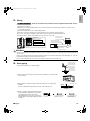
Accessories
A – H ,
A Mounting plate
1
D Remote controller holder
1
G Operation manual
1
B Titanium apatite photocatalytic
air-purifying filter
2
E Dry battery AAA. LR03
(alkaline)
2
H Installation manual
1
C Wireless remote controller
1
F Indoor unit fixing screw
(M4 × 12L)
2
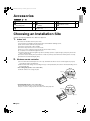
Choosing an Installation Site
• Before choosing the installation site, obtain user approval.
1.
Indoor unit
• The indoor unit should be sited in a place where:
1) the restrictions on installation specified in the indoor unit installation drawings are met,
2) both air inlet and air outlet have clear paths met,
3) the unit is not in the path of direct sunlight,
4) the unit is away from the source of heat or steam,
5) there is no source of machine oil vapour (this may shorten indoor unit life),
6) cool (warm) air is circulated throughout the room,
7) the unit is away from electronic ignition type fluorescent lamps (inverter or rapid start type) as they may shorten the
remote controller range,
8) the unit is at least 1m away from any television or radio set (unit may cause interference with the picture or sound),
9) install at the recommended height (1.8m).
2.
Wireless remote controller
1) Turn on all the fluorescent lamps in the room, if any, and find the site where remote controller signals are properly
received by the indoor unit (within 7m).
2) Make the DIP switch settings. Set according to the type of unit purchased by the customer. The default settings are on
the heat pump side.
• For cooling only (Outdoor unit model: RKS)
Set the DIP switch on the cooling only side.
DIP switch
Heat pump
Cooling only
• For heat pump (Outdoor unit model: RXS)
Check that the DIP switch are on the heat pump side.
If they are set on the cooling only side, move them to the heat pump side.
DIP switch
Heat pump
Cooling only
■English
2
01_EN_3P248445-1B.fm Page 3 Thursday, August 5, 2010 9:46 AM
Indoor Unit Installation Drawings
n How to attach the indoor unit
A Mounting plate
Hook the claws of the bottom frame
to the mounting plate.
If the claws are difficult to hook,
remove the front grille.
A Mounting
plate
Clip
n How to remove the indoor unit
Push up the marked area (at the
lower part of the front grille) to
release the claws. If it is difficult to
release, remove the front grille.
Bottom frame
Front grille
Mark (rear side)
Screws
(field supply: M4 × 25L)
The mounting plate
should be installed on a
wall which can support the
weight of the indoor unit.
30mm or more
from ceiling
Caulk
pipe hole
gap
with putty.
Cut thermal insulation
pipe to an appropriate
length and wrap it with
tape, making sure that no
gap is left in the insulation
pipe’s cut line.
Front panel
Wrap the insulation pipe with
the finishing tape from bottom
to top.
50mm or more from walls
(on both sides)
INTELLIGENT EYE
sensor
Air filters
Screws
(M4 × 16L)
B Titanium apatite photocatalytic
air-purifying filter (2)
Filter frame
Titanium apatite
photocatalytic
air-purifying filter
Service lid
Opening service lid
Service lid is opening/closing type.
Opening method
1) Remove the service lid screws.
2) Pull out the service lid diagonally
down in the direction of the arrow.
3) Pull down.
Tab
Air filter
C
Wireless
remote
controller
Fixing screws for remote
controller holder
(field supply: M3 × 20L)
Before screwing the remote
controller holder to the wall,
make sure that control
signals are properly
received by indoor unit.
D
Remote
controller holder
INTELLIGENT EYE sensor
CAUTION
• Do not hit or violently push the INTELLIGENT EYE sensor. This can lead to damage and malfunction.
• Do not place large objects near the sensor. Also keep heating units or humidifiers outside the sensor’s detection area.
3
■English
01_EN_3P248445-1B.fm Page 4 Thursday, August 5, 2010 9:46 AM
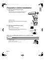
1.
English
Preparation before Installation
Removing and installing front panel
• Removal method
Hook fingers on the tabs on the left and right of the main body, and open
until the panel stops. Slide the front panel sideways to disengage the
rotating shaft. Then pull the front panel toward you to remove it.
• Installation method
Align the tabs of the front panel with the grooves, and push all the way in.
Then close slowly. Push the center of the lower surface of the panel firmly to
engage the tabs.
2.
Removing and installing front grille
Push the
rotating shaft
of the front
panel into the
groove.
Upper hook
¡¡¡ mark area
(3 locations)
• Removal method
1) Remove front panel to remove the air filter.
2) Remove 3 screws from the front grille.
3) In front of the {{{ mark of the front grille, there are 3 upper hooks.
Lightly pull the front grille toward you with one hand, and push down on the
hooks with the fingers of your other hand.
Lightly pull the front
grille toward you with
one hand, and push
down on the hooks with
the fingers of your other
hand. (3 locations)
Push
down.
Upper hook
When there is no work space because the unit is close to ceiling
CAUTION
• Be sure to wear protection gloves.
Place both hands under the center of the front grille, and while pushing up, pull it toward you.
1) Push up.
• Installation method
1) Install the front grille and firmly engage the upper hooks (3 locations).
2) Install 3 screws of the front grille.
3) Install the air filter and then mount the front panel.
2) Pull toward you.
■English
4
01_EN_3P248445-1B.fm Page 5 Thursday, August 5, 2010 9:46 AM
Preparation before Installation
How to set the different addresses
1
2
ADDRESS
Jumper
EXIST
CUT
When two indoor units are installed in one room,
the two wireless remote controllers can be set
for different addresses.
1) Remove the metal plate electrical wiring
cover.
(Refer to the Removal/attachment methods
of metal plate electrical wiring covers.)
2) Cut the address jumper (JA) on the printed
circuit board.
3) Cut the address jumper in the remote
controller.
ADDRESS:JA
3.
JB
JA
JC
ADDRESS
EXIST
CUT
4.
1
2
When connecting to an HA system
(wired remote controller, central remote controller etc.)
1) Remove the metal plate electrical
wiring cover.
(Refer to the Removal/
attachment methods of metal
plate electrical wiring covers.)
2) Attach the connection cord to the
S21 connector and pull the
harness out through the notched
part in the figure.
3) Replace the electrical wiring cover
as it was, and pull the harness
around, as shown in the figure.
Mount the edge of the metal
plate electrical wiring cover
passing under the tabs.
HA connector
(S21)
Insert the metal plate electrical
wiring cover into the insertion
mouth.
• Removal methods of metal plate electrical wiring cover
1) Remove the front grille. (3 screws)
2) Remove the electrical wiring box. (1 screw)
3) Remove the 4 tabs, and pull and disconnect the metal plate electrical wiring cover from the single insertion mouth.
Screw
2) Remove the electrical
wiring box. (1 screw)
5
3) Remove the 4 tabs, and pull and disconnect the
metal plate electrical wiring cover from the
single insertion mouth.
■English
English
01_EN_3P248445-1B.fm Page 6 Thursday, August 5, 2010 9:46 AM
• Attachment methods of metal plate electrical wiring cover
Attach the metal plate electrical wiring cover as shown below.
1) Lean the metal plate electrical wiring cover as shown in the figure and insert the tab on the lower side.
2) Push in the upper part of the metal plate electrical wiring cover and attach the 4 tabs.
Tab
CAUTION
Lean the metal plate
electrical wiring cover as
shown in the figure and
insert the tab on the lower
side.
Make sure that the shaded part
(
) will not go inside the
electrical wiring box.
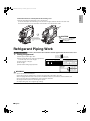
Refrigerant Piping Work
With a multi indoor unit , install as described in the installation manual supplied with the multi outdoor unit.
1.
Flaring the pipe end
1) Cut the pipe end with a pipe cutter.
2) Remove burrs with the cut surface facing downward
so that the chips do not enter the pipe.
3) Put the flare nut on the pipe.
4) Flare the pipe.
5) Check that the flaring is properly made.
(Cut exactly at
right angles.)
Remove burrs.
Flaring
Set exactly at the position shown below.
A
Die
A
Flare tool for R410A
Conventional flare tool
Clutch-type
Clutch-type (Rigid-type) Wing-nut type (Imperial-type)
0-0.5mm
1.5-2.0mm
1.0-1.5mm
Check
Flare’s inner
surface must
be flaw-free.
The pipe end must
be evenly flared in
a perfect circle.
Make sure that the
flare nut is fitted.
WARNING
• Do not use mineral oil on flared part.
• Prevent mineral oil from getting into the system as this would reduce the lifetime of the units.
• Never use piping which has been used for previous installations. Only use parts which are delivered with the unit.
• Do never install a drier to this R410A unit in order to guarantee its lifetime.
• The drying material may dissolve and damage the system.
• Incomplete flaring may cause refrigerant gas leakage.
■English
6
01_EN_3P248445-1B.fm Page 7 Thursday, August 5, 2010 9:46 AM
Refrigerant Piping Work
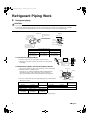
2.
Refrigerant piping
CAUTION
• Use the flare nut fixed to the main unit. (To prevent cracking of the flare nut by aged deterioration.)
• To prevent gas leakage, apply refrigeration oil only to the inner surface of the flare. (Use refrigeration oil for R410A.)
• Use torque wrenches when tightening the flare nuts to prevent damage to the flare nuts and gas leakage.
Align the centres of both flares and tighten the flare nuts 3 or 4 turns by hand. Then tighten them fully with the torque wrenches.
[Apply oil]
[Tighten]
Apply refrigeration oil to
Do not apply refrigeration
Torque wrench
the inner surface of the
flare.
oil to the outer surface.
Flare nut
Spanner
Piping union
Flare nut
Do not apply refrigeration
oil to the flare nut avoid
tightening with over torque.
Flare nut tightening torque
Gas side
Liquid side
1/2 inch
5/8 inch
1/4 inch
49.5-60.3N l m
61.8-75.4N l m
14.2-17.2N l m
(505-615kgf l cm)
(630-770kgf l cm)
(144-175kgf l cm)
2-1. Caution on piping handling
1) Protect the open end of the pipe against dust and moisture.
2) All pipe bends should be as gentle as possible. Use a pipe bender
for bending.
Wall
Be sure to
place a cap.
Rain
If no flare cap is
available, cover the
flare mouth with
tape to keep dirt or
water out.
2-2. Selection of copper and heat insulation materials
• When using commercial copper pipes and fittings, observe the following:
1) Insulation material: Polyethylene foam
Heat transfer rate: 0.041 to 0.052W/mK (0.035 to 0.045kcal/mh°C)
Refrigerant gas pipe’s surface temperature reaches 110°C max.
Choose heat insulation materials that will withstand this temperature.
Inter-unit wiring
Gas pipe
Liquid pipe
Gas pipe
insulation
2) Be sure to insulate both the gas and liquid piping and to provide insulation
dimensions as below.
Gas side
60 class
O.D. 12.7mm
Liquid side
71 class
O.D. 6.4mm
O.D. 15.9mm
Minimum bend radius
40mm or more
50mm or more
30mm or more
Thickness 0.8mm Thickness 1.0mm Thickness 0.8mm
(C1220T-O)
(C1220T-O)
(C1220T-O)
Liquid pipe
insulation
Finishing tape
Gas pipe thermal insulation
60 class
I.D. 14-16mm
71 class
I.D. 16-20mm
Thickness 10mm Min.
Drain hose
Liquid pipe
thermal insulation
I.D. 8-10mm
3) Use separate thermal insulation pipes for gas and liquid refrigerant pipes.
7
■English
01_EN_3P248445-1B.fm Page 8 Thursday, August 5, 2010 9:46 AM
1.
English
Indoor Unit Installation
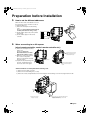
Installing the mounting plate
• The mounting plate should be installed on a wall which can support the weight of the indoor unit.
1) Temporarily secure the mounting plate to the wall, make sure that the panel is completely level, and mark the boring
points on the wall.
2) Secure the mounting plate to the wall with screws.
Recommended mounting plate retention spots and dimensions
Recommended mounting plate retention
spots (9 spots in all)
Place a leveler on raised tab.
(Bolt size: M10)
(Bolt size: M10)
100
55
125
90
290
Use tape
measure
as shown.
Position the
end of tape
measure at ∇ .
φ80
52
52
φ80
60
83
413.5
44.5
100
99.5
1050
Through-the-wall
Drain hose position hole φ80mm
* The removed pipe port cover can be
kept in the mounting plate pocket.
Gas pipe end
Liquid pipe end
unit: mm
Removed pipe
port cover
A Mounting
plate
2.
Boring a wall hole and installing wall embedded pipe
• For walls containing metal frame or metal board, be sure to use a wall
embedded pipe and wall cover in the feed-through hole to prevent possible
heat, electrical shock, or fire.
• Be sure to caulk the gaps around the pipes with caulking material to prevent
water leakage.
1) Bore a feed-through hole of 80mm in the wall so it has a down slope toward
the outside.
2) Insert a wall pipe into the hole.
3) Insert a wall cover into wall pipe.
4) After completing refrigerant piping, wiring, and drain piping, caulk pipe hole
gap with putty.
3.
Inside
Wall embedded pipe
(field supply)
Outside
Caulking
φ80
Wall hole cover
(field supply)
Wall embedded pipe
(field supply)
Inter-unit wiring
1) Open the front panel, then remove the service lid.
2) Pass the inter-unit wiring from the outdoor unit through the feedthrough wall hole and then through the back of the indoor unit. Pull
them through the front side. Bend the ends of tie wires upward for
easier work in advance. (If the inter-unit wiring ends are to be
stripped first, bundle wire ends with adhesive tape.)
3) Press the bottom frame of the indoor unit with both hands to set it on
the mounting plate hooks. Make sure the wires do not catch on the
edge of the indoor unit.
■English
Hang indoor unit’s hook here.
A Mounting plate
When stripping the
ends of inter-unit wiring
in advance, bind right
ends of wires with
insulating tape.
Inter-unit wiring
8
01_EN_3P248445-1B.fm Page 9 Thursday, August 5, 2010 9:46 AM
Indoor Unit Installation
4.
Laying piping, hoses, and wiring
4-1. Right-side, right-back, or right-bottom
piping
Remove pipe port cover
here for right-side piping
1) Attach the drain hose to the underside of the
refrigerant pipes with adhesive vinyl tape.
2) Wrap the refrigerant pipes and drain hose together
with insulation tape.
Remove pipe port cover
here for right-bottom piping
3) Pass the drain hose and refrigerant pipes through the
wall hole, then set the indoor unit on the mounting
plate hooks by using the
markings at the top of the
indoor unit as a guide.
Right-back piping
Right-bottom
piping
Bind coolant pipe and drain hose
together with insulating tape.
A Mounting plate
4-2. Left-side, left-back, or left-bottom piping
1) Replace the drain plug and drain hose.
2) Attach the drain hose to the underside of the
refrigerant pipes with adhesive vinyl tape.
Remove pipe port cover
here for left-side piping
Left-side piping
Left-back piping
Remove pipe port cover here for left-bottom piping
Left-bottom piping
3) Be sure to connect the drain hose to the drain port in
place of a drain plug.
How to set drain plug
ap
No g
Do not apply lubricating oil (refrigeration oil)
when inserting.
Application of causes deterioration and drain
leakage of the plug.
Insert a hexagonal wrench (4mm).
4) Shape the refrigerant pipe along the pipe path
marking on the mounting plate.
5) Pass drain hose and refrigerant pipes through
the wall hole, then set the indoor unit on
mounting plate hooks, using the
markings at
the top of indoor unit as a guide.
6) Pull in the inter-unit wiring.
A
Mounting plate
Drain hose
Caulk this hole
with putty or
caulking material.
Bind with plastic
tape.
7) Connect the inter-unit piping.
8) Wrap the refrigerant pipes and drain hose together with insulation tape as
right figure, in case of setting the drain hose through the back of the
indoor unit.
9) While exercising care so that the inter-unit wiring do not catch indoor unit,
press the bottom edge of indoor unit with both hands until it is firmly
caught by the mounting plate hooks. Secure indoor unit to the mounting
plate with indoor unit fixing screws (M4 × 12L).
Wrap insulating tape around the bent portion
of refrigerant pipe.
Overlap at least half the width of the tape
with each turn.
Drain hose
A
Mounting
plate
Refrigerant
pipes
Bottom frame
F Indoor unit fixing screw
(M4 × 12L) (2 point)
4-3. Wall embedded piping
Follow the instructions given under left-side, left-back, or leftbottom piping.
Insert the drain hose to this depth so it won’t be pulled out of
the drain pipe.
Insert the drain hose to this depth so
it won’t be pulled out of drain pipe.
50mm
or more
Outer wall
9
Inner wall
Drain hose
Vinyl chloride drain pipe
(VP-30)
■English
5.
English
01_EN_3P248445-1B.fm Page 10 Thursday, August 5, 2010 9:46 AM
Wiring
With a multi indoor unit , install as described in the installation manual supplied with the multi outdoor
unit.
1) Strip wire ends (15mm).
2) Match wire colours with terminal numbers on indoor and outdoor unit’s terminal blocks and firmly screw wires to the
corresponding terminals.
3) Connect the earth wires to the corresponding terminals.
4) Pull wires to make sure that they are securely latched up, then retain wires with wire retainer.
5) In case of connecting to an adapter system. Run the remote controller cable and attach the S21.
6) Shape the wires so that the service lid fits securely, then close service lid.
Firmly fix the wires with
the terminal screws.
Terminal block
Electrical component box
1 2
3
Outdoor unit
Shape wires so that the
service lid will fit securely.
Firmly secure wire retainer so that
wires sustain no external stress.
Use the specified
wire type.
1 23
When wire length exceeds
10m, use 2.0mm diameter wires.
Indoor
unit
Wire retainer
LN
1
2
3
Firmly fix the wires with
the terminal screws.
H05RN
WARNING
• Do not use tapped wires, stranded wires, extension cords, or starburst connections, as they may cause overheating, electrical
shock, or fire.
• Do not use locally purchased electrical parts inside the product. (Do not branch the power for the drain pump, etc., from the
terminal block.) Doing so may cause electric shock or fire.
• Do not connect the power wire to the indoor unit. Doing so may cause electric shock or fire.
6.
Drain piping
The drain hose should
be inclined downward.
1) Connect the drain hose, as described right.
No trap is permitted.
Do not put the end
of the hose in water.
3) When drain hose requires extension, obtain an extension hose commercially
available.
Be sure to thermally insulate the indoor section of the extension hose.
Indoor unit
drain hose
φ18
2) Remove the air filters and pour some water into the drain pan to check the water
flows smoothly.
Extension drain hose
4) When connecting a rigid polyvinyl chloride pipe
(nominal diameter 13mm) directly to the drain
hose attached to the indoor unit as with
embedded piping work, use any commercially
available drain socket (nominal diameter 13mm)
as a joint.
■English
φ18
Heat insulation tube
(field supply)
Drain hose supplied with
the indoor unit
Commercially available drain
socket
(nominal diameter 13mm)
Commercially available rigid
polyvinyl chloride pipe
(nominal diameter 13mm)
10
01_EN_3P248445-1B.fm Page 11 Thursday, August 5, 2010 9:46 AM
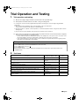
Trial Operation and Testing
1.
Trial operation and testing
1-1 Measure the supply voltage and make sure that it falls in the specified range.
1-2 Trial operation should be carried out in either cooling or heating mode.
• In cooling mode, select the lowest programmable temperature; in heating mode, select the highest programmable
temperature.
1) Trial operation may be disabled in either mode depending on the room temperature.
Use the remote controller for trial operation as described below.
2) After trial operation is complete, set the temperature to a normal level (26°C to 28°C in cooling mode, 20°C to 24°C in
heating mode).
3) For protection, the system disables restart operation for 3 minutes after it is turned off.
1-3 Carry out the test operation in accordance with the operation manual to ensure that all functions and parts,
such as louver movement, are working properly.
• The air conditioner requires a small amount of power in its standby mode. If the system is not to be used for some
time after installation, shut off the circuit breaker to eliminate unnecessary power consumption.
• If the circuit breaker trips to shut off the power to the air conditioner, the system will restore the original operation
mode when the circuit breaker is opened again.
Trial operation from remote controller
1)
2)
3)
4)
5)
2.
Press “ON/OFF” button to turn on the system.
Press “TEMP” button (2 locations) and “MODE” button at the same time.
Press “TEMP” button and select “ ”.
Press “MODE” button.
Trial operation terminates in approx. 30 minutes and switches into normal mode. To quit a trial operation, press
“ON/OFF” button.
Test items
Test Items
Symptom
(diagnostic display on RC)
Indoor and outdoor units are installed properly on solid bases.
Fall, vibration, noise
No refrigerant gas leaks.
Incomplete cooling/heating
function
Refrigerant gas and liquid pipes and indoor drain hose extension are
thermally insulated.
Water leakage
Draining line is properly installed.
Water leakage
System is properly earthed.
Electrical leakage
The specified wires are used for inter-unit wiring connections.
Inoperative or burn damage
Indoor or outdoor unit’s air inlet or air outlet has clear path of air.
Stop valves are opened.
Incomplete cooling/heating
function
Indoor unit properly receives remote control commands.
Inoperative
The heat pump or cooling only mode is selectable with the DIP switch of the
remote controller.
Remote controller
malfunctioning
11
Check
■English
00_CV_3P248445-1B.fm Page 2 Wednesday, August 4, 2010 9:30 AM
Two-dimensional bar code is a code
for manufacturing.
3P248445-1B
M08B303A
(1010) HT