1
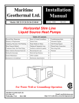
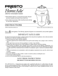
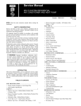
Maritime
Geothermal Ltd.
Installation
Manual
NORDIC® models R-45-55-65
Revision 3.1
Friday, February
High Efficiency “R”eversible
Liquid Source Heat Pumps
Table of Contents
Heat Pump System Requirements .....
3
Groundloop Requirements.......... 13
CFM available ...........................
25
Optimum Placement .......................
5
Pump Modules ...........
15
Trouble Shooting Guide ..............
26
Plumbing the Heat Pump ................
7
Antifreeze Solution ..........
14
Electrical Diagrams .....................
29
Safety Controls ..............................
9
Component Layout ................
20
Plenum Heater .....................
31
Starting the Heat Pump ...................
11
Performance Ratings ...............
24
Warranty ...................................
32
Maintenance ..................................
11
Heat Exchanger Pressure Drop .. 25
Horizontal
Vertical
Water Well or Groundloop Operation
Maritime Geothermal Ltd.
P.O. Box 413
Petitcodiac, N.B.
E0A 2H0
Email:[email protected]
www.discribe.ca/nordic
Friday, February 04, 2000
Maritime Geothermal Ltd.
A NORDIC® Groundwater Heat Pump System
Energy Input:
Solar
Geothermal
Groundwater
Water Pump System
NORDIC®
Groundwater
Heat Pump
Ductwork
(Heat Distribution)
Disposal of
thermally altered
water
Surface
Irrigation
Domestic
Subsurface
Pond/
Return Well
Underground Water
Page .... 2
Leaching
Maritime Geothermal Ltd.
Friday, February 04, 2000
NORDIC® Heat Pump System Prerequisites
1.
2.
3.
4.
5.
There are five specific parts or sub-systems to a groundwater heat pump installation:
The source of energy (groundwater) .........................................
Water Well
The method of supplying energy to the heat pump .................
Water Pump System
Converting the energy to a useable form ...................................
Heat Pump
Distributing the heat ..................................................................
Ductwork
Returning the exhaust water to the earth for reheating ..............
Water disposal
Water Well Requirements
1. A DRILLED well of 5'' diameter or larger.
2. Well casing properly sealed or grouted into rock.
3. Water flow preferably entering well at a depth of 75
ft. or more.
4. Temperature of well at least 40° F. (Normally 45 °F.)
5. Well must be able to supply requirements of BOTH
heat pump and residence usage at the same time with maximum drawdown from static level of 30 ft.
Duct Systems
A duct system capable of supplying the required air flow
is of utmost importance.
• Generally allow 100 cfm for each floor grill.
• All leads to the grills should be 6'' in diameter (28 sq.in.
each).
Nordic® R-45 will heat up to 1800 sq.ft.
Nordic® R-55 will heat up to 2700 sq.ft.
Nordic® R-65 will heat up to 3500 sq.ft.
Water Requirements For
Nordic® Heat Pumps
Note: These are minimum water requirements based on an
Model
Heat Pump
Home
Total
Nordic R-45
8 Igpm
3
11
Nordic R-55
10 Igpm
3
13
Nordic R-65
12 Igpm
3
15
Assuming at least R-20 walls and R-40 ceiling
•
•
Your main hot air trunks should be at least 75% of the
square surface area of leads being fed at any given point.
Return air grills should have the same total square surface
area as the total of your supply grills. (minimum)
The square surface area of your return trunks should
Air Flow Available from each heat pump
entering water temperature of 46° F.
Igpm = Imperial gallons per min.
Nordic® R-45 models
Nordic® R-55 models
Nordic® R-65 models
Water Pump System
1. A submersible pump is generally required.
2. Must be able to pump the required water flow listed
above at a minimum of 30 psig. at the dynamic pumping
depth of your well.
3. Make sure you select the pump using the pump manufacturers pump chart.
4. Use a minimum of 30 gal. equivalent air bladder tank.
The Heat Pump
A heat pump with Btu output capable of heating the
home in all winter weather conditions should be selected as
follows:
Page .... 3
1600 cfm
1900 cfm
2100 cfm
equal the square surface area of the grills being handled at any
given point along the trunk.
It is VERY IMPORTANT that all turns in both the supply trunks and the return trunks be made with TURNING RADII. Remember that air is a fluid and, just like water, it does
not like to go around SHARP corner.
Nordic® R-45 could have up to 16 hot air grills.
Nordic® R-55 could have up to 19 hot air grills.
Nordic® R-65 could have up to 21 hot air grills.
Friday, February 04, 2000
Maritime Geothermal Ltd.
NORDIC® “R” Series - Open Loop Disposal Methods
Page .... 4
Maritime Geothermal Ltd.
Friday, February 04, 2000
Discharge Water Methods
1. You do NOT necessarily have to have a return well.
2. 80% of our customers do one of the following with
their return or waste water:
A. Run it into a drain or ditch.
B. Pond, river or stream.
C. Leaching field.
In most instances if you run the water right out on top of
the ground it will soak back into the ground in less than 50 ft.
of travel. If suitable care is taken to insure that the drain pipe
runs downhill and the end of the pipe is protected by a bale of
hay or spruce bows etc. the end of the pipe will not freeze.
When snow comes it will usually cover the entire process
much like a small spring.
The above information is intended to give the prospective user/purchaser some insight as to the general requirements for a successful application of the NORDIC® heat
pump.
Typical P/T – “Pete’s” Plug & Thermometer Stems
Unpacking
When the heat pump reaches it's destination it should be
unpacked to determine if any damage has occurred during
shipment. Any visible damage should be noted on the carrier's
freight bill and a suitable claim filed at once.
ing and general maintenance can be carried out with a minimum of difficulty. Raising the heat pump off the floor a few
inches is generally a good practice since this will prevent unnecessary rusting of the bottom panel of the unit.
The heat pump is well constructed and every effort
has been made to insure that it will arrive intact, however it is
in the customer's best interest to examine the unit thoroughly
when it arrives.
We recommend that the heat pump be placed on a piece
of 2'' Styrofoam covered with 1/4'' plywood. The Styrofoam
will smooth out any irregularities
in the cement floor while the plywood will distribute the
weight of the NORDIC® unit evenly over the Styrofoam.
This process will also deaden the compressor noise emitted
from the bottom of the cabinet.
Optimum Placement
The NORDIC heat pump has an air-filter rack which can
be removed for easy entry through a doorway or to facilitate
As an alternative, several pieces of 2''x 4'' lumber can be
moving the unit with a furniture cart. Simply remove the two
placed under the unit running from the electrical connection
screws which hold the end cap in place, slide the cap off and
side to the filter rack side of the heat pump. Laying the 2''x
push the rack back off it's rails. When the heat pump is in
4'''s in this manner will give the best support since they will
place the filter rack can be reinstalled with the removable end
be at right angles with the internal steel compressor and heat
(where the filter is removed) facing the
exchanger support.
direction that allows easiest access for
changing the filter.
In to Heat Pump
To achieve the greatest efficiency,
the heat pump should be centrally located
Brass fitting
in the home with respect to the the condion water
tioned space. This design provides the utlines to heat
most in economy and comfort and usually
The NORDIC heat pump must be supplied
can be accomplished in harmony with the
with an adequate water supply, since in
design of the home. A heating system canessence, water is the fuel for the unit. It is
Water
not be expected to produce an even
imperative that the flow requirements
warmth throughout the household when it
listed in the engineering section be closely
is located at one end of the structure and
adhered to.
the warm air is transmitted with uninsu1/8” D stem Therlated metal ductwork.
Maritime Geothermal Ltd. recommometers & PresIf possible the three main service
mends the installation of a water flow medoors should remain clear of obstruction
sure gauges attached ter on the discharge line so that the exact
for a distance of (2) two ft. so that servicamount of water flowing can be deter-
Plumbing the Heat
Pump
Page .... 5
Friday, February 04, 2000
Maritime Geothermal Ltd.
NORDIC® “R” Series Typical Plumbing & Ductwork
Page .... 6
Maritime Geothermal Ltd.
Friday, February 04, 2000
mined at a glance.
Plumbing lines, both supply and discharge, must be
of adequate size to handle the water flow necessary for the
heat pump. For distances less than 40 ft. from the pressure
tank, 3/4'' copper or plastic lines should be run while for
longer distances we recommend that 1'' plastic or copper lines
should be run to the heat exchanger. Similarly, a 1'' line
should be run from the discharge pipe to the method if disposal.
Ideally there will be water flow available in excess of
the requirement of the heat pump. In such a situation the
proper pump can be selected to maintain a pressure of 30 to
40 psig. on the lines when the heat pump is operating. However in some cases a well can supply a heat pump only if the
minimum requirement for water is used.
Water flow to the heat pump can be controlled very accurately by the installation of a reverse action pressure valve
in the discharge line of the unit. Another method of regulating
the flow is by the use of a “DOLE” valve. This valve will
automatically control the amount of water flowing through it
by varying the diameter of a flexible rubber orifice through
which the water passes. If either of such valves is needed they
can be supplied and installed by your dealer.
All water line valves on both the supply and discharge
lines should be either BALL or GATE valves since a GLOBE
valve will create too much restriction across the line possibly
causing the heat pump to trip out on it's low pressure safety
cutout control as a result of insufficient water flow.
Install a P/T (Pete’s Plug)plug on the Water (IN) and
Water (OUT) lines just outside the heat pump so that it is easy
to record the water in and out temperatures and pressures accurately. (See Diagram on Page 5)
Exposed water lines will have a tendency to sweat when
the heat pump is in operation, therefore it is recommended
that both the water supply and discharge lines be insulated
with suitable insulation.
Hot Water Connections
Connection to the hot water generator feature of the heat
pump is accomplished by teeing into an electric or oil fired
hot water tank with a capacity of 40 gal. minimum. A typical
piping diagram is shown elsewhere in this manual. Be sure to
note the position of the check valve and the direction of water
flow.
One should be sure the tank is filled with water and
is under pressure before activating the heat pump. Slightly
loosen the copper union on the hot water discharge pipe to
allow air to escape from the system before the unit is started.
This step will make certain that the water circulator is floode
with water when it is started.
Since the pump is water lubricated, damage will occur
to the pump if it is run dry for even a short period.
The union on the discharge water line may have to be
purged of air several times before good circulation is obtained. A hand placed several feet down the line will sense
when the water is flowing.
The thermostats on the hot water tank should be set to
120°F. since the heat pump has an internal thermostat set at a
low of 130°F. By setting the tank thermostats as described,
the heat pump will try to keep the tank above the cut-in point
Page .... 7
of the electric element settings thus generating hot water from
the heat pump only. During summer, or periods of high demand, the electric elements will energize to help make hot
water.
3/4" MPT Copper
or PVC adapter
Vent (if required)
3/4" FPT
2"
1/8" per ft.
2"
Typical Condensate Drain connection
Air FilReturn
3-1/2"
R (Horiz.) - Condensate Drain location
NOTE: If (2) shut-off valves are located on the
hot water lines as shown in the diagram, be sure that
the valves are open when the heat pump is operating.
If both valves are closed when the heat pump is operating, water will expand in the hot water heat exchanger
and could cause damage to the hot water circulator
pump.
Condensate Drain
You will notice in the piping diagram that there is a
small drain pipe to the left of the front door. This drain allows
the condensed water vapor which forms during the airconditioning cycle to escape to a suitable area of your selection. On a very humid day there could be as much as 25 gallons of water formed. Care should be taken in the spring to
insure that this pipe is not plugged with dust that has collected
Friday, February 04, 2000
Maritime Geothermal Ltd.
Revision 3.3
Desuperheater Piping
Models: R-45-55-65
Style: Horizontal
Maritime Geothermal Ltd.
Water-to-Air Heat Pumps
Date: January 1992
Drawn By: G.Kaye
Title: Top & Bottom Access Port Tanks
An alternate to the single domestic hot water
tank setup is the design
shown at left. This design maximizes your
benefit from the heat
pump desuperheater by
allowing more storage
and also insures that the
water in the final tank
has not been mixed with
cold water thus reducing the output temperature.
The heat pump shown above is a horizontal unit
although the two tank technique is applicable to
both the vertical and horizontal models.
Page .... 8
Maritime Geothermal Ltd.
Friday, February 04, 2000
during the winter since the water formed will overflow into
the bottom of the heat pump.
Water Disposal Methods
Water disposal methods vary from area to area however
some consideration should be made to prevent the cooled discharge water from immediately coming in contact with the
supply source. Generally speaking, returning water to a second well, pond lake or stream is acceptable while returning
water to the same well will usually cool the water so much
that the heat pump will shut off on it's low pressure / temperature safety control.
A return well should be a minimum of 80 ft. from the
supply well for residential applications. The water returned to
the well will not be necessarily be pumped into the same aquifer, depending on underground conditions, but the return well
does have to be able to supply the same quantity of water as
the amount you wish to recharge into it.
If the static level (level when not being pumped) of a
well is high (10 to 20 ft. from the surface) it may be necessary
to place a well cap on the well to keep the return water from
flowing out the top of the well. This cap is commonly required since a certain amount of pressure is needed to force
the return water back down the well if the static level is high.
Return wells are not always the answer and to some
it may be more satisfactory to pump the water to a pond or
away into the woods.
Water recharged naturally through percolation into the
soil is an alternative to a recharge well. The water discharged
will generally soak into the ground within a distance of 50 to
100 ft. If care is taken to make sure the end of the pipe does
not freeze then this method of disposal works well.
Safety Controls
The NORDIC heat pump has two built in safety controls
which are designed to protect the unit from situations which
could damage it.
A. LOW PRESSURE / TEMPERATURE CONTROL
The low refrigerant pressure / temperature control is
designed to shut the unit down if the refrigerant evaporating
pressure becomes too low thus risking the danger of freezing
conditions in the evaporator.
There are only (4) reasons why this control would
activate and they are:
• 1. Low water flow. (See requirements for each
model.
• 2. Low water temperature. (Below 40 °.F.)
• 3. Dirty or fouled heat exchanger.
• 4. Low refrigerant charge.
B. HIGH PRESSURE CONTROL
The second safety control is a high pressure safety limit
which monitors compressor discharge pressure. This device
will not normally trip unless there is an interruption in air
flow. Such a situation could occur if the blower motor or fan
belt failed or if the heat pump had an extremely dirty air filter.
Page .... 9
If either of these controls trips it will activate a LOCK-OUT
RELAY which prevents the unit from restarting until power
to the control circuit is broken (by turning the thermostat to
the OFF position and then back on again) or the electrical
supply to the unit is broken by opening the heat pump breaker
and then closing it again. If one of these controls trips there is
a serious problem with the system and it must be rectified if
the unit is to maintain good service.
NOTE: Under no circumstances should the heat
pump lock-out relay be reset more than twice in an hour.
If the the heat pump is shutting off because of LOW or
NO water flow then repeated resetting of the unit could
cause the heat exchanger to freeze and rupture destroying
the heat pump.
Electrical Nordic® (R)
Models
The NORDIC unit is supplied with an opening for 3/4''
conduit nipple on the right blank side of the unit. An additional knockout (1/2") is provided to facilitate connection of
a plenum heater blower control wire if required. Above this
is another 3/8'' hole for the thermostat wire. A wiring diagram
is located inside the electrical box cover for quick reference
and although the connections to be made are quite simple,
Maritime Geothermal Ltd. recommends that a properly qualified electrician be retained to make the connections and wire
the thermostat.
The NORDIC unit comes supplied with a thermostat and
connections are clearly marked on the control box. Using a 8conductor (18 gauge) wire suitable for the job, connect the
terminals in the heat pump electrical box to the corresponding
terminals on the thermostat. An additional 4-conductor wire
will be required for low voltage control of a NORDIC plenum
heater if required.
Ductwork
Ductwork layout for a NORDIC® heat pump will differ
from normal design in the number of leads and size of main
trunks required. Air temperature leaving the heat pump is normally 95º to 105º F., much cooler than that of a conventional
warm air furnace. To compensate for this, larger volumes of
lower temperature air must be moved and consequently duct
sizing must be able to accommodate the greater air flow without creating a higher static pressure or high velocity at the
floor diffusers. Maritime Geothermal Ltd. recommends that
the static pressure be kept below .2 inches of water total. Return ducts should ideally be placed in every room and be sized
50% larger than corresponding supplies. In some instances the
number of floor diffusers will actually double when compared
to the number that would normally be used for a warm air oilfired furnace.
NOTE: See the duct sizing chart in the engineering section of this manual.
Starting the Heat Pump
Friday, February 04, 2000
Maritime Geothermal Ltd.
Revision 3.3
Color: Caissie Grey
Models: R-45-55-65
Style: Horizontal
Maritime Geothermal Ltd.
Hot Water Tank Connections
Date: Friday, February 04,
Drawn By: G.Kaye
Title: Top Access Port tank piping
Diagram above shows a horizontal “R” series heat pump connected to a heat pump pre-heat tank with
both the inlet and exit access ports at the top of the tank.
Always observe the “HOT IN” and “HOT OUT” markings on the heat pump and the direction of the
check valve when connecting your linesets.
Page .... 10
Maritime Geothermal Ltd.
Friday, February 04, 2000
BEFORE starting the heat pump the following areas
should be rechecked to assure proper operation.
1. Check all high voltage field wiring and electrical connections inside the control box for good connection.
2. Check all low voltage thermostat to make sure they
are connected properly. Place thermostat HEAT-OFF-COOL
switch in the OFF position.
3. Turn on the main power switch. Allow the power to
remain ON without starting the unit for a period of 4 hours.
Refrigerant migrates to the compressor oil when the compressor is unheated. A crankcase heater is standard equipment on
your heat pump and it will warm the compressor, dispelling
the liquid refrigerant. Compressor damage can occur if the
heat pump has been brought in from a cold location and immediately started up.
4. Turn on the water supply and check all plumbing for
leaks.
5. Check the hot water tank to be sure it is filled with
water before energizing the circuit.
NOTE: In a low ambient air start-up the hot water tank
should be energized for at least 4 hours before the heat pump
is started. A combination of low air temperature and 45º F.
water in the hot water tank can sometimes cause the unit to
shut down on it's low pressure control. If this happens close
ONE valve in the hot water circuit to temporarily shut off the
flow to the hot water generator. Do not shut off both valves
since water expanding in the hot water generator loop may
cause damage to the circulator pump housing. When the home
has come up to temperature open the valve for normal hot water operation. Slightly open the union on the hot water discharge pipe to make sure that all air is out of the system and
the circulator pump is flooded with water.
6. Make sure the air filter is clean and in place.
7. Vacuum out any dust and debris that may have collected in the unit during installation. Check the condensate
drain to be sure that it is free of obstruction.
8. Make sure the unit is sitting level so that condensate
water will not overflow the catch pan.
9. Make sure the proper time-delay fuse has been installed in the fuse box.
10. Have the following tools on hand and know how to
use them.
• A refrigeration gauge set.
• An electronic or other accurate thermometer
• An amprobe.
• A water flow meter.
11. Connect your refrigeration gauge set.
12. After the 4 hour warm-up period place the thermostat function switch in the HEAT position, turn up the thermostat. The compressor, blower and hot water circulator will
start.
NOTE: If the unit is equipped with an electric TACO
water valve the blower will start first followed by the compressor in 30 to 60 seconds. When the TACO water valve is
fully open, an internal switch activates the compressor circuit.
mately 53 to 58 psig. while the head or discharge pressure
(red gauge) should be in the area of 225 to 275 psig. Record
this information on the warranty test card.
14. Using an electronic thermometer or other accurate
thermometer, record the supply water temp.''IN'' and the water
temperature ``OUT''.
The outlet water temperature should be from 4° to 7° F.
cooler than the inlet water temperature.
15. Record the supply water flow in gpm.
16. Record the return air temperature by drilling a small
hole in the return air plenum approximately 2 ft. from the filter rack and inserting the thermometer's sensing device.
17. Similarly record the discharge air temp. There
should be a rise across the air exchanger of from 25° to 35°F.
18. At the electrical disconnect switch place the amprobe jaws around the supply wires and record the current in
each.
19. Place the thermostat function selector in the COOL
position and turn down the stat to a temperature that will
cause the air-conditioning to begin. When the thermostat selector switch is set in the COOL mode the reversing valve
will be energized. The blower should start followed by the
compressor. The outlet temperature will be approx. 10° to
20°.F. cooler than the return air temp.
General Maintenance
As with any piece of equipment there will eventually be
some maintenance to be done on the heat pump. Several areas
will need attention and they are as follows:
1. Change the air filter when required.
2. Oil the blower motor once a year.
3. Clean the groundwater heat exchanger.
4. Inspect the blower belt for cracks & wear.
5. Insure the condensate drain is clean.
Reversible NORDIC® heat pumps are equipped with
coaxial type heat exchangers. These heat exchangers are not
manually cleanable however they can be cleaned with a sulfamic acid solution commonly marketed under the trade name
"Iron-Out". If you suspect that the water being pumped
through the unit is of a poor quality or you notice a decrease
in performance after several years of use it may be necessary
to have the liquid heat exchanger cleaned.
Maritime Geothermal recommends that a qualified serviceman be retained to carry out this procedure since the solution involved is highly corrosive.
13. Observe the readings on the high and low pressure
gauge set. When the home reaches a temperature of 65 to 70
°.F. the suction pressure (blue gauge) should be approxiPage .... 11
Friday, February 04, 2000
Maritime Geothermal Ltd.
Diagram A.
Design # 2
Design # 1
Diagram A.
Shown above are several of the many possible horizontal loop layouts which have been successfully employed in various types of ground conditions.
Design # 1
Shown is a typical reverse return header system and 2 parallel loops. On a 2 ton system each of these loops would be 500 ft.
long with 4 ft. spacing between the “U” sections, 10 ft spacing between the loops and buried 6 ft. underground.
Design # 2 is a single loop of 1-1/4” to 1-1/2” diameter pipe with a length of 500 ft. x the tonnage of the system and buried
to a depth of 6 ft. underground. Individual runs of pipe should be kept a minimum of 10 ft. apart.
Diagram B.
Design # 3
Design # 4
Design # 3.
Shown is a vertical borehole reverse-return header system. Vertical systems generally require 125 to 175 ft of borehole per
ton of heat pump for successful heat transfer to take place with the earth. Boreholes should be spaced a minimum of 10 ft apart
while if land is available, 15 ft. spacing will produce better results.
Boreholes should be tremie grouted from bottom to top with bentonite or a mixture of bentonite and neat cement for proper
conduction with the earth.
Design # 4.
Shown here is a typical series loop design using 1-1/4 to 1-1/2” pipe for the loops. Some designs incorporate a double “U”
tube assembly down the well which allows for better heat transfer between the earth and the loop.
NOTE
Many other loop designs are in common use throughout North America. For a more comprehensive manual on earthloop
design refer to our Earthloop Design Manual or contact IGSHPA (International Ground Source Heat Pump Association) and request their earth systems dealer training manual.
Page .... 12
Maritime Geothermal Ltd.
Friday, February 04, 2000
RHR- Series
SeriesClosed
ClosedLoop
LoopInstallation
InstallationInformation
Information
Horizontal Groundloops
Introduction
Many commercial buildings select a vertical or
horizontal closed loop as the earth heat exchanger either
because of a lack of available groundwater or for the reduced
maintenance costs which can be obtained when compared to
open loop systems. Often the problems which occur in a
geothermal system are associated with the the wells, pumps,
or the direct result of utilizing poor quality water or water
which is contaminated with sand or other foreign materials.
Such contamination can cause premature failure with pumps,
water valves, heat exchangers and return wells.
To reduce these problems to a minimum a closed
secondary heat exchange system is constructed with Type
3408 Polyethylene Plastic Pipe specifically engineered for
the job. Materials such as PVC and polybutylene are not
recommended since their underground joining process is not
as reliable as the fusion process used with type 3408
polyethylene. The earthloop heat exchanger can consist of a
single long length of plastic commonly called a series style
heat exchanger or more commonly is found as a number of
parallel loops connected to a reverse return header system.
The series system for homes or light commercial applications
up to 10 tons normally is constructed with 1-1/4” to 2”
diameter pipe while the parallel system uses multiple branch
loops from 3/4” to 1” connected to a larger header pipe
system of 1-1/4” to 2” diameter. The parallel system offers
several advantages such as:
• Less expensive pipe.
• Easier to handle the smaller pipe.
• Lower pressure drop
• Smaller circulator pump(s)
Of course on larger commercial systems it would not be
unusual to find header systems with up to 6” diameter pipe for
fluid flow into and out of the building.
Socket Fusion
Mechanical joints or metal fittings of any kind are not
acceptable underground in an earth loop system due to large
temperature fluctuations which may loosen and break clamps
and the possibility of eventual corrosion perforation in
couplings and “T’s”.
Fittings and joints are socket or butt fused together into
one contiguous unit using a technique developed by the gas
industry. A heater tool with the appropriate faces heats both
the pipe and fitting for a prescribed period of time and then
the two pieces are quickly removed from the heater, inserted
together and held in place until the joint cools. When properly
done the resulting joint is stronger than the original pipe with
no chance of leaks or breaks. For more information on butt
and socket fusion techniques see our website at (http://www.
discribe.ca/nordic/fusion.htm) or request a copy of the
Central Tools Butt and Socket fusion manual.
Horizontal groundloop systems are most commonly
used where land is readily available since they are cheaper to
construct than their vertical counterparts. Although many
configurations are available, we have found that a parallel
system with one (1) 500 ft. “U” pipe per ton placed in a 250
ft. x 4 ft. wide x 6 ft. deep trench is easy to construct and
provides ample ground impact area to adequately supply a 32°
F or better Entering Fluid Temperature to the heat pump even
in the most severe winter months. (See opposite Diagram A.)
Several companies including “Thermalworks” and the
International Ground Source Heat Pump Association (igshpa)
provide modeling software to size the heat pump to the home
and then size the loop to the demand of the home and heat
pump. Consideration is given to many factors such as type of
ground, moisture content and configuration of loops desired.
It is often possible to shorten loop lengths and resulting costs
when using some of the newer “Slinky” designs of
earthloops. A comprehensive manual dedicated entirely to the
installation of Groundloops is available from Maritime
Geothermal Ltd. which describes in detail the techniques
involved in installing a closed loop system.
Vertical Groundloops
Vertical groundloop systems are generally the system of
choice for commercial and institutional buildings since the
land area available is often limited to parking lots with some
adjacent landscaped areas.
Boreholes of 4 to 6 in. diameter are drilled with
conventional drilling equipment usually to a depth of less than
300 ft. Each “ton” of heat pump installed requires
approximately 150 ft. of borehole. The 3/4” to 1”plastic pipe
“U” tubes are fused together using socket fusion techniques
and then pressure tested for leaks at 100 psig. using either
water or air. Provision should be made to allow enough extra
pipe to extend from the boreholes to the proposed location of
the header system. Prior to inserting down the hole the
assembly must be filled with water so that buoyancy will be
at a minimum when inserting the “U” tube. Cap the ends so
that mud and debris cannot enter the loops during insertion
and grouting. A piece of heavy rebar or galvanized pipe is
attached to the bottom 10 to 15 ft of the “U” tube with tape to
add weight to the assembly and also prevent it from curling
up and gouging into the side of the borehole during insertion.
The entire length of the assembly should be taped every 10 ft.
to create greater rigidity in the “U” tube assembly as it is
installed in the borehole. The “U” tube is inserted into the
borehole and the borehole is tremie grouted from bottom to
within 10 ft. of the top with a mixture of neat cement and
bentonite or 100% bentonite. When using bentonite refer to
the manufacturers instructions for mixing and select a product
that provides a total solids content of from 25 to 30% when
Page .... 13
Friday, February 04, 2000
Maritime Geothermal Ltd.
Page .... 14
Maritime Geothermal Ltd.
Friday, February 04, 2000
mixed.
Horizontal trenches from 4 to 6 ft. deep are dug
alongside the boreholes to the building so that a reverse return
(first pipe out on the supply line is the last pipe back on the
return line) header pipe arrangement can be constructed to tie
all the loops together. Lay out the header system so that air
cannot be easily trapped in the header using a technique
approved by igshpa or the local governing authority. Use a
shovel to break away any ground between the trench and the
Table 1. Antifreeze Percentages by Volume
Protection down 10°F
Methanol
25%
Propylene Glycol 38%
15°F
21%
30%
20°F
16%
22%
25°F
10%
15%
boreholes and dig a relief no less than 30 times the diameter
of the pipe to allow the pipe to bend to the header pipe
without kinking. Be very careful not to disturb the original
ground under the relief so that you do not have to worry about
the pipe being kinked through compaction of the earth under
the pipe after the trench is backfilled. Fuse the individual
smaller loops to the main header loops and extend these into
the home by drilling through the concrete wall or by rising up
the outside of the basement wall or slab and entering the
structural part of the home or building above grade. Any
piping that comes within 10 ft. of the structure should be
insulated with 3/8” to 1/2” closed cell armaflex insulation to
prevent freezing from occurring near any structural part of the
building. Likewise, all piping inside the building must be
insulated to prevent condensation and subsequent dripping
onto floors or walls.
Circulator Pump Module
“Pete’s plugs” should be installed on both the entering and
leaving lines at the heat pump. The P/T plug will allow the
installer or homeowner to check water flow through the loop
by measuring the pressure difference through the heat
exchanger and comparing this pressure drop to that of the
appropriate model in the engineering section. (see Pressure
Drop vs. Water Flow Table)
Flushing & Purging the
Earthloop
Once the earthloop has been installed and all
connections are completed to the heat pump and pumping
station the entire plumbing system should be pressure tested
with air to 60 psig. to make sure there are no leaks on any of
the inside fittings. Soap all joints and observe that the
pressure remains constant for 1 hour.
NOTE: If you use pressure gauges permanently installed
on the system as in the case of a demonstration situation etc.
be careful not to exceed the maximum pressure rating of the
gauges to avoid damage to their mechanism.
When satisfied all connections are leak free, release the
air pressure and connect a flush cart (see diagram) to the
flushing access ports at the pump station. A temporary
flushing system can alternately be constructed using a 45 gal.
barrel and a pump with sufficient volume and head capability
to circulate fluid at a velocity of at least 2 ft./min. through all
parts of the loop. Begin pumping water through the earthloop
making sure that the intake of the pump stays submerged at
all times by continuously adding water from a hose etc. Water
flowing back on the return line should be directed below the
water level in the barrel or flush tank to prevent air being
mixed with the outgoing water. Once the lines have been
filled and no more air bubbles are appearing in the line, adjust
When the groundloop has been brought inside the home
or building to the location of the heat pump it must be
connected to the pump module which generally consists of (1)
Grundfoss® Model UPS 26-99 or Taco® Model 0011 pump
for systems up to 3 ton and (2) pumps for systems up to 5 ton.
These units must be able to pump at least 2.5 to 3 USgpm. per
ton of heat pump for proper operation of the system. To
calculate the size of pumps required use the pressure drop
tables for the diameter and type of tubing used along with all
elbows, T’s etc and the pressure drop through the unit’s heat
exchanger to arrive at:
( total ft of head) x (3 gpm/ton) x (No. of tons)
Table 2. US Gal. of fluid per 100 ft. of pipe
Type of Pipe
Diameter
Volume (US
gal.)
Copper
1”
4.1
1-1/4”
6.4
1-1/2”
9.2
Rubber Hose
1”
3.9
Polyethylene
3/4” IPS SDR11
2.8
1” IPS SDR11
4.5
1-1/4” IPS SDR11
8.0
1-1/2” IPS SDR11
10.9
2” IPS SDR11
18.0
Heat Exchanger
Average
1.5
Flush Cart Tank
15”D x 3 ft. high
28
Heat Pump to Circulator
Piping
The heat pump must be connected to the circulator pump
module with a lineset suitable for the flow required with
minimum pressure drop. Common line sizes would be 3/4”
rubber or plastic for heat pumps from 1 to 2.5 ton while for
unit sizes 3 through 5 ton, 1” lines should be used. The
installation of P/T plugs (pressure / temperature) pronounced
the flow valves to circulate water through the heat pump
using the same technique as described above. When all air is
removed reverse the flow of water through the lines by
Page .... 15
Friday, February 04, 2000
Maritime Geothermal Ltd.
Revision 3.3
Two Pump Kit
Models: R-45-55-65
HP Style: Vertical
Maritime Geothermal Ltd.
Water-to-Air Heat Pumps
Date: Friday, February 04,
Drawn By: G. Kaye
Page .... 16
Title: Loop Pump Module
Maritime Geothermal Ltd.
Friday, February 04, 2000
Water Flow Rate vs. Pressure Drop Through Heat Exchanger
Model
4 usgpm
6 usgpm
8 usgpm
10 usgpm
12 usgpm
14 usgpm
1.5
1.5
3.7
5.0
6.5
R-55
1.6
2.4
3.4
4.5
5.7
R-60
1.1
1.8
2.4
3.1
3.9
R-45
16 usgpm
Nordic® R-Series
interchanging the flush cart lines and purge again. You will
be able to visibly tell when all air is removed.
Installing Antifreeze
Solution
In most mid and northern areas of the US and in all of
Canada it is necessary to condition the loop fluid by the
addition of some type of antifreeze solution so that it will not
freeze during operation in the winter months. This antifreeze
is required because the loop fluid will normally reach a low
entering temperature of 28°F to 32°F. and refrigerant
temperatures inside the heat pump’s heat exchanger may be
as low as 20°F cooler. See the antifreeze concentration chart
at left for details of freeze protection afforded under different
concentrations.
NOTE: Add enough antifreeze to allow for a
temperature 20°F lower than the expected lowest loop
fluid temperature entering the heat pump.
NOTE: Although many different antifreeze solutions
have been employed in geothermal systems, the alcohols
such as methanol or ethanol have the most desirable
characteristics for earthloop application. The overall heat
transfer characteristics of these fluids remain high although
care must be taken when handling pure alcohols since they
are extremely flammable. Once mixed in a typical 25% by
volume ratio with water the solution is not flammable. In
situations where alcohols are not allowed as a loop fluid due
to local regulations then propylene glycol is a non-toxic
alternative which can be substituted . Propylene glycol
should only be used in cases where alcohols are not
permitted since the heat transfer characteristics are less
desirable and it becomes more viscous at low temperatures
which increases pumping watts. The volume of fluid that
your loop system holds can be closely estimated by totaling
the number of ft. of each size pipe in the system and
referencing Table 2. the for approximate volume per 100 ft.
When the volume of the loop has been calculated and
the appropriate amount of antifreeze is ready for addition by
referencing Table 1. , drain the equivalent amount of water
from the flush cart or mixing barrel and replace it with the
antifreeze. When using alcohols be sure to inject it below the
water line to reduce initial volatility of the pure antifreeze. If
the loop is large and the tank is small it may be necessary to
refill the tank with antifreeze several times to get all the
antifreeze into the loop. Pump the loop for 5 to 10 minutes
longer to insure the remaining fluid has been well mixed.
Initial Pressurization
At this point open all valves in the flow circuit and
slowly close off the supply and return flush cart valves in a
manner that leaves about 20-30 psig. on the system. If an air
bladder expansion tank is used it should be charged to the
above pressure before actual water pressure is put on the
system . Systems employing a commercially available loop
pump kit that do not have an expansion tank, thermometers
and pressure gauges will experience a greater fluctuation of
pressure in the loop between winter and summer. This
fluctuation is normal since expansion and contraction of the
loop fluid must be handled by the elasticity of the plastic
loop. Pressurize the loop to a pressure of 45 psig. when
installing a system in the fall going into the heating season. If
installing in spring or summer charge to 25 psig.
After operating the machine for a period of time, any
residual air in the system can be bled off through valved
vertical standpipes in the pump module. If pressure drops
below 25 psig. add additional water / antifreeze mix with the
purge pump to bring the pressure back to the original setting.
Inserting Plastic “U” tube in 4” Borehole
Page .... 17
Friday, February 04, 2000
Maritime Geothermal Ltd.
Duct Sizing Guide
Required Diameter
CFM
in inches
Return Air Required
Diameter
CFM
Rectangular Equivalents
37
5
2.25 x 10
3x8
3.5 x 6
4 x 5.5
5x5
63
5
2.25 x 10
3x8
3.5 x 6
4 x 5.5
100
6
3.25 x 10
4x8
5x6
152
7
3.25 x 14
4 x 11
212
8
4 x 15
226
8
277
5
37
5x5
6
63
5.5 x 5.5
6x6
7
100
5 x 8.5
6x7
6.5 x 6.5
8
152
5 x 12
6 x 10
7x8
8x8
9
212
4 x 15
5 x 12
6 x 10
7x8
8x8
10
226
9
5 x 15
6 x 12
7 x 10
8x9
8.5 x 8.5
10
277
304
9
5 x 15
6 x 12
7 x 10
8x9
8.5 x 8.5
12
304
393
10
6 x 15
7 x 13
8 x 11
9 x 10
9.5 x 9.5
12
393
411
12
7 x 18
8 x 16
9 x 14
10 x 12
11 x 11
12
411
655
12
7 x 18
8 x 16
9 x 14
10 x 12
11 x 11
14
655
680
14
8 x 22
9 x 19
10 x 17
11 x 15
12 x 14
13 x 13
14
680
995
14
8 x 22
9 x 19
10 x 17
11 x 15
12 x 14
13 x 13
16
995
1325
16
8 x 30
10 x 22
12 x 18
14 x 16
15 x 15
18
1325
1450
16
8 x 30
10 x 22
12 x 18
14 x 16
15 x 15
20
1450
1750
18
8 x 40
10 x 30
12 x 24
14 x 20
16 x 17
16.5 x 16.5
20
1750
2000
18
8 x 40
10 x 30
12 x 24
14 x 20
16 x 17
16.5 x 16.5
22
2000
2250
20
10 x 38
12 x 30
14 x 26
16 x 22
18 x 19
18.5 x 18.5
22
2250
2600
20
10 x 38
12 x 30
14 x 26
16 x 22
18 x 19
18.5 x 18.5
24
2600
2900
22
12 x 36
14 x 30
16 x 26
18 x 23
20 x 20
24
2900
3400
22
12 x 36
14 x 30
16 x 26
18 x 23
20 x 20
26
3400
3600
24
14 x 38
16 x 32
18 x 28
20 x 25
22 x 22
26
3600
4300
24
14 x 38
16 x 32
18 x 28
20 x 25
22 x 22
28
4300
5250
26
16 x 38
18 x 32
20 x 30
22 x 24
24 x 24
30
5250
6125
28
18 x 38
20 x 34
22 x 30
24 x 28
26 x 26
32
6125
6500
28
18 x 38
20 x 34
22 x 30
24 x 28
26 x 26
34
6500
7250
30
20 x 40
22 x 38
24 x 32
26 x 30
28 x 28
34
7250
7800
30
20 x 40
22 x 38
24 x 32
26 x 30
28 x 28
36
7800
8500
32
22 x 40
24 x 38
26 x 34
28 x 32
30 x 30
36
8500
9200
32
22 x 40
24 x 38
26 x 34
28 x 32
30 x 30
38
9200
9800
34
24 x 42
25 x 40
26 x 38
28 x 34
30 x 32
31 x 31
38
9800
10900
34
24 x 42
25 x 40
26 x 38
28 x 34
30 x 32
31 x 31
40
10900
28 x 40
30 x 36
32 x 34
33 x 33
30 x 42
32 x 38
34 x 36
35 x 35
30 x 45
34 x 40
36 x 38
37 x 37
Page .... 18
`
Maritime Geothermal Ltd.
Friday, February 04, 2000
NORDIC® Series R-45-55-65
Engineering and Performance Data
Friday, February 04,
Page .... 19
Friday, February 04, 2000
Maritime Geothermal Ltd.
Revision 2.3
Color: Caissie Grey
Models: R-45-55-65
Style: Vertical
Maritime Geothermal Ltd.
Water-to-Air Heat Pumps
Date: January 1992
Drawn By: G. Kaye
Page .... 20
Title: Cabinet & Piping Layout
Maritime Geothermal Ltd.
Friday, February 04, 2000
Revision 2.3
Color: Caissie Grey
Models: R-45-55-65
Style: Horizontal
Maritime Geothermal Ltd.
Title: Cabinet & Piping Layout
1.25
2.50
26.07
DOOR
19.00
4.22
18.00
Refrigerant Air Coil
Filter rack area
29.00
Drawn By: G. Kaye
1.00
Date: January 1992
33.00
Water-to-Air Heat Pumps
Electric
Box
BACK SIDE
(Return Air Side)
52.00
22.00
28.00
BLOWER DOOR
1.00
FRONT DOOR SIZE
28"W x 31"H
31.00
Actual G-12
14.00
Blower opening
13.5" x 15.5"
2.00
3.19
1.00
2.66
16.15
27
.0
0
FRONT VIEW
17.13
6.99ø
4.00
0
.0
52
3.50
3.50
RIGHT SIDE
DOOR
4.50
33.00
7.50
33.00
5.00
5.00
3.25
22.00
1.00
0.63
LEFT SIDE DOOR
31"H x 22"W
33.00
31.00
27.00
LEFT SIDE VIEW1.75
Page .... 21
Friday, February 04, 2000
Maritime Geothermal Ltd.
Thermostat
Disconnect
Switch
Electrical Supply and Thermostat Wire Sizes
Model
R-45
R-55
R-65
45,000
55,000
65,000
29
32
37
# 8-3
# 6-3
# 6-3
Max. Fuse Size
40
40
50
Max. breaker size
40
40
50
# 18
# 18
# 18
8
8
8
Nominal BTU output
Min. circuit ampacity
Minimum wire size
Thermostat wire size
Thermostat conductors
Domestic Hot Water Generator Specifications
Temperature
(IN) °F.
Temp
(OUT) °F.
Temperature
Rise °F.
% of
Total
R-45
(Igal/hr)
R-55
(Igal/hr)
R-65
(Igal/hr)
40
150
110
20
10
11.8
14.5
45
150
105
18
9.4
11.1
13.7
50
150
100
15
8.33
9.8
12.1
60
150
90
12
7.33
8.6
10.6
75
150
75
10
7.33
8.6
10.6
90
150
60
8
7.33
8.6
10.6
110
150
40
5
6.87
5.4
10
Page .... 22
Maritime Geothermal Ltd.
Friday, February 04, 2000
Maritime Geothermal Ltd. NORDIC® “R” - Series
Premium Features - Reversing Series
•
•
•
•
•
•
•
•
•
•
Return Air Filter
Oversize high efficiency air coil.
Belt drive blower
with ball bearings.
Non sticking reversing valve.
High efficiency ball
bearing, PSC style
motor.
Galvanized drip
tray.
Sight glass
(optional)
Suction accumulator.
Bi-flow filter driers.
Thermostatic ex-
•
•
•
•
•
•
•
•
•
•
pansion valve.
Hot Water
(IN)
Hot Water
(OUT)
Hot Water circulator
High & Low access
ports.
Slow closing water
valve.
High Efficiency coaxial
heat exchanger.
Supply water (OUT)
Supply water (IN)]
Insulated water coil.
High efficiency Tecum-
(Front) Plumbing side
•
•
•
•
•
Baked enamel cabinet with satin galvanized condensate
tray and floor.
Components accessible from three
sides.
Heavy duty electrical components.
Hard start kit on all
models.
Blower motor field
•
•
•
•
•
(Back) Electrical Box Side
Page .... 23
replaceable.
Remote reset
lock-out relay system.
Acoustically insulated cabinet.
Cabinet spot
welded together
for superior
strength.
Removable and
reversible filter
rack.
Friday, February 04, 2000
Maritime Geothermal Ltd.
Capacity Data
Model R-45-HAC (nominal 3 ton)
Heating
EWT
Igpm Lpm
LWT
Diff
HAB
Pres
Drop
EAT
LAT
Diff
Btu's
Out
Comp
Amps
Comp
Watts
Blower
Amps
Blower
Watts
Total
Watts
COP
CSA
COP
Suct
Disc
Pres
70
8
36
61
8.8
40135 5.47
70.2
98
28
52875
17.3
3250
3.92
386.6
3636.9
4.2
3.4
80.4
263
61
8
36
53.6
7.7
34984 5.41
70.5
95
25
46408
16.9
3133
4
387.1
3520.2
3.9
3.13
69.7
251
55
8
36.3
48
7.2
34712 5.71
70.2
94
24
45481
16.4
3040
4.32
379.7
3420
3.9
3.13
63.8
243
45
8
36.2
39
6
28842 5.88
70
91
21
40592
15.7
2879
4.25
384.6
3263.7
3.6
2.9
52.2
227
38
8
36
32.2
5.4
24632
69.8
88
19
35562
15.4
2703
4.29
396.8
3100.1
3.4
3.14
43.8
209
32
8
36.2
27
4.8
22007 5.21
70.2
87
17
32892
14.7
2606
4.15
403.7
3009.3
3.2
2.99
38.5
201
LWT
Diff
Water Pres
Output Drop
EAT
LAT
Diff
Sens.
cooling
Latent
Total
Cooling Cooling
Comp.
Amps
Comp
Watts
Blower
Amps
Blower Total
Watts Watts
EER
CSA
EER
10549 40730
12.38
1956
4.28
407
2363 17.2
12.7
407
2725 14.1
10.8
407
2890 13.2
12.3
5.3
Cooling
EWT
Igpm Lpm
50
8
36
60.6 10.8 40987 5.38
79.5
64
16
30082
70
8
36.2
79.7 10.1 36785 5.41
79.7
65
15
29125
9103
38502
13.67
2317
4.23
77
8
36.2
86.9
80.2
65
15
29696
8211
38427
14.27
2484
4.17
Comp: ZR40K1 Scroll
90
8
36
99.7
Voltage: 230/1/60
9.7
36755 5.41
BM: HE / .33 Marathon
9.6
35813 5.35
79.9
66
14
Entering Air: 70DB / 60WB
G-10 Blower
27472
7615
CFM: 1850
2-row / 6-circuit air coil
34878
15.5
2821
4.16
BTSSC-60 water coil
412
3232 10.8
10.1
External Static: .15” WC
In accordance with ARI 325 & ARI 330 standards and CAN/CSA C446-M94
Capacity Data
Model R-55-HAC (nominal 4 ton)
Heating
EWT
Igpm Lpm
LWT
Diff
HAB
Pres
Drop
EAT
LAT
Diff
Btu's
Out
Comp
Amps
Comp
Watts
Blower
Amps
Blower
Watts
Total
Watts
COP
CSA
COP
Suct
Disc
Pres
70
10
45.2
60.8
9.2
55223 8.68
70
115
45
69507
21.9
4686
3.26
302.6
4988.8
4.1
3.3
80.4
287
60
10
45.2
52.7
7.6
45619 8.74
70.2
109
39
60529
19.7
4271
3.3
309.9
4581
3.9
3.08
68.1
262
55
10
45.2
48.2
7
41975 8.65
69.8
106
37
57229
18.6
4051
3.33
308.4
4359.7
3.9
3.03
62.2
249
45
10
45.2
39.2
5.9
35271 8.83
69.6
100
30
48898
17.2
3680
3.36
324.1
4004.2
3.6
2.76
51.5
227
39
10
45.2
33.3
5.4
29991 8.94
70.9
98
27
43980
16.2
3407
3.45
319.7
3726.3
3.5
3.16
44.1
214
32
10
45.2
27.3
4.9
26789 9.03
69.8
94
25
39563
15.1
3211
3.47
318.7
3529.9
3.3
2.98
38
202
LWT
Diff
Water Pres
Output Drop
EAT
LAT
Diff
Sens.
cooling
Latent
Total
Cooling Cooling
Comp.
Amps
Comp
Watts
Blower
Amps
Blower Total
Watts Watts
EER
CSA
EER
80.1
56
25
38410 21940 61107
14.8
3104
3.39
330
3434 17.8
14.3
80.4
57
24
36618 20729 58064
15.81
3363
3.36
324
3686 15.7
12.8
80.1
58
23
35149 18045 54121
17.01
3636
3.4
340
3976 13.6
11.2
3832
3.38
334
4165 12.8
10.7
Cooling
EWT
Igpm Lpm
50
8
36
60
8
36.3
70
8
35.8
64.9 14.9 59450
5.8
74.1 14.4 56902 5.83
84
14
53146 5.56
Comp: AV5549G
BM: HE / .33 Marathon
Voltage: 230/1/60
Entering Air: 70DB / 60WB CFM: 1850
77
8
36.2
91
G-10 Blower
13.8 52035 5.65
80.4
58
4 row / 12-circuit air coil
22
BTSSC-84 water coil
34326 18545 53513
17.79
External Static: .2” WC
In accordance with ARI 325 & ARI 330 standards and CAN/CSA C446-M94
Page .... 24
Maritime Geothermal Ltd.
Friday, February 04, 2000
Capacity Data
Model R-65-HAC (nominal 5 ton)
Heating
EWT
Igpm Lpm
LWT
Diff
HAB
Pres
Drop
EAT
LAT
Diff
Btu's
Out
Comp
Amps
Comp
Watts
Blower
Amps
Blower
Watts
Total
Watts
COP
CSA
COP
Suct
Disc
Pres
70
12
54.1
61.3
8.5
61029 6.88
70
111
42
82262
31.2
6454
8.22
515
6969
3.5
3.21
78.8
268
60
12
54.2
52.3
7.6
54706 6.94
70
107
38
74313
28.6
5873
8.65
534
6407
3.4
3.14
66.9
250
50
12
54.3
48.4
6.8
48989 7.06
71
105
35
68601
27.2
5609
8.46
521
6131
3.3
3.08
61.5
241
45
12
54.1
43.7
6.3
45156 7.09
70
103
33
65208
26.17
5321
8.33
516
5837
3.26
2.95
56
230
40
12
54.2
34.9
5.2
37399 7.33
70
98
28
56473
23.7
4808
8.59
536
5344
3.1
2.78
46.5
210
32
12
54.3
27.3
4.7
30871
7.8
69.6
95
25
50379
22.2
4452
8.05
513.6
4965
3.0
2.77
39.7
200
LWT
Diff
Water Pres
Output Drop
EAT
LAT
Diff
Sens.
cooling
Latent
Total
Cooling Cooling
Comp.
Amps
Comp
Watts
Blower
Amps
Blower Total
Watts Watts
EER
CSA
EER
Cooling
EWT
Igpm Lpm
50
8
36.3
67.8 17.6 66472 3.21
80.1
58
23
43189
25046 69127
23.85
3962
8.0
433
4395 15.7
14.1
60
8
36.2
77.7 17.3 63497 3.09
80.4
58
23
43215
21873 63497
25.09
3952
8.4
459
4411 14.4
13.2
70
8
36.3
87.1 16.6 59391 3.18
79.7
58
21
41381
20041 62109
26.36
4111
8.3
453
4564 13.6
12.1
77
8
35.6
93.6 16.8 58296 3.38
79.5
59
20
38988
19792 59457
27.28
4233
8.4
457
4690 12.7
11.6
Comp: AH5561E
BM: HE / .5 Marathon
G-12 Blower
4 row / 12-circuit air coil
Voltage: 230/1/60
Entering Air: 70DB / 60WB
CFM: 2000
External Static: .2” WC
BTSSC-84 water coil
In accordance with ARI 325 & ARI 330 standards and CAN/CSA C446-M94
Water Flow Vs. Pressure drop Tables
BTSSC-60 Turbotec® Exchanger
BTSSC-84 Turbotec® Exchanger
(Igpm)
(Psig)
(Psig) c/w valve
(Igpm)
(Psig)
(Psig) c/w valve
12
6.71
12.2
12
6.88
12.5
10
4.35
8.65
10
4.85
8.83
8
2.85
5.41
8
3.15
5.83
6
1.92
2.97
6
2.0
3.65
4
1.10
1.35
4
1.35
2.0
Air Flow Vs. External Static Pressure
G-10 Delhi Blower
G-12 Delhi Blower
External Static Pres.
CFM available
External Static Pres.
CFM available
.10
1966
.10
2182
.15
1885
.15
2092
.20
1777
.20
1972
.25
1657
.25
1839
.30
1581
.30
1755
Page .... 25
Friday, February 04, 2000
Maritime Geothermal Ltd.
NORDIC® Heat Pump System Trouble Shooting Guide
Fault
Possible Cause
Verification
Recommended Action
Compressor not
operating
Power Failure
Electric circuit test shows no
voltage on the line side of
compressor contactor.
Check for blown fuse at heat
pump’s disconnect box or
blown fuse
Disconnect switch open Voltmeter shows no voltage on Determine why the disconnect
the line side of the compressor switch was opened, if all is
contactor.
OK close the switch.
Fuse blown
At heat pump disconnect box,
voltmeter shows voltage on the
line side but not on the load
side.
Replace fuse with proper size
and type. (Time-delay) type
“D”
Check total load on system.
Low voltage
Voltmeter shows abnormally
low voltage (Below 210 v) at
heat pump disconnect switch.
Call power company.
Burned out motor
Ohmmeter shows no resistance Determine cause and replace
between common and run ter- motor.
minals or between common
and start terminals. Note: Be
sure compressor overload has
had a chance to reset. If comp.
is hot this may take several
Thermal overload on
compressor tripped.
Ohmmeter shows reading
If windings are open or overwhen placed across R and S
load is faulty, replace comterminals and infinity between pressor.
C & R or C & S.
Make sure the internal overload has had time to reset.
Faulty compressor con- Voltage on line side with con- Replace contactor.
tactor.
tactor held closed, but no voltage on one or both terminals
on the load side.
Points pitted or burned.
Seized compressor due
to locked or damaged
mechanism.
Compressor attempts to start
but trips it’s internal overload
after a few seconds.
Attempt to “rock” compressor
free. If normal operation cannot be established, replace
compressor.
Faulty run capacitor.
Check with ohmmeter for
shorts, open etc.
Replace if faulty.
Page .... 26
Maritime Geothermal Ltd.
Friday, February 04, 2000
Fault
Possible Cause
Verification
Compressor not
operating
Open control circuit.
•
•
•
Compressor repeatedly
locks out on it’s LOW
pressure safety control.
Compressor
“short cycles”
Recommended Action
Thermostat not calling for Locate open control and determine cause. Replace faulty
heat.
High or low pressure limit control if necessary.
open.
Lock-out relay energized.
Open contacts on low pressure
safety limit switch.
Lock out relay energized.
Water heat exchanger frozen.
Check for “low” or “no” water.
Restore proper water flow.
Thaw out heat exchanger.
Intermittent contact in Normal operation except too
Check anticipator in thermoelectrical control circuit. frequent starting and stopping. stat. Make sure setting is for
“longest cycle” or max. amps.
Unit trips off on Low water flow
“LOW” suction
pressure control.
Manually open water valve
Check well pump for proper
and measure water flow with a operation. Check water valve
flowmeter.
for proper operation. Replace.
Water supply too cold.
Measure temperature of water. Increase flow to proper gpm.
Check flow rate with spec.
sheet to determine if proper
gpm is available.
Ambient air too cold.
Measure return air temp.
Should be above 60°F.
Faulty low pressure ctrl. Refrigerant pressure control
Faulty low “temp” ctrl. should open on drop at approx.
45 psig.
Temp. ctrl. will open in about
1 minute if water flow is interrupted or if unit is run with
suction pressure below 50
Restrict air flow temporarily
until room comes up to temBoth controls should reset
automatically. Heat pump can
then be restarted by resetting
the lock-out relay. (Turn
power off then back on) Replace faulty control if it will
not reset.
Low refrigerant charge. Check water temp. and flow. Add refrigerant slowly. Check
Clean heat exchanger. If suc- for possible leaks.
tion is still low check return air
temp. Normal suction is 50-60
Low or “no” air
conditioning
No water flow. Unit
trips out on it’s high
pressure limit.
Check flow with flowmeter or Check water pump operation.
other method.
Reversing valve “stuck” Unit works well in the heating
in the heating mode.
mode but there is no loud rushing sound when unit is quickly
switched to cooling mode.
Page .... 27
Check or replace valve solenoid and if necessary replace
entire reversing valve assembly.
Friday, February 04, 2000
Maritime Geothermal Ltd.
Fault
Possible Cause
Verification
Recommended Action
Low or “no” air
conditioning
Open control circuit
Thermostat not set to signal
operation
Turn room thermostat down.
Reduced air flow or return air temperature too
cold. Unit trips out on
low suction pressure
control.
Check for:
1. Dirty air filter.
2. Fan belt slipping.
3. Broken blower belt.
4. Inoperative blower motor.
Insufficient hot
water
Circulator pump not op- Visually inspect the pump to
erating.
see if shaft is turning. Use an
amprobe to measure current
draw.
1. Replace filter
2. Tighten blower belt.
3. Replace belt.
4. Replace blower motor.
Replace if faulty.
Blockage or restriction
in the water line or hot
water heat exchanger.
Check water flow and power Remove obstruction in water
to pump. Check water lines for lines. Acid treat the domestic
obstruction
hot water coil.
Thermostat limit is
open.
Check contact operation.
Should close at 120°F and
open at 140°F.
Replace thermostat if faulty.
Disconnect switch open, Check both line and load sides Replace blown fuse or breaker
or fuse blown in electri- of fuses. If switch is open de- or close switch.
cal supply to hot water termine why.
Reset button tripped on Check voltage at elements
hot water tank.
with multimeter.
Push reset button.
Thermostat on hot water Visually inspect the setting.
tank set too low. Should
be set at 120°F.
Readjust the setting to 120°F.
Heat pump not running
enough hours to make
sufficient hot water.
Temporarily turn up the tank
thermostats until colder
weather creates longer run cy-
Note the amount of time the
heat pump runs in any given
hour.
Trouble Shooting Tools
Dole flow control Valve
Refrigeration Gauges
Amprobe
Digital Thermometer
In-line Flowmeter
Page .... 28
The Dole® flow control is a simple, selfcleaning device designed to deliver a constant volume of water from any outlet
whether the pressure is 15 psig or as high as
125 psi. The controlling mechanism consists
of a flexible orifice that varies it’s area inversely with pressure so that a constant flow
is maintained.
Friday, February 04, 2000
Maritime Geothermal Ltd.
NORDIC® “R” Series Electrical Box Connections
Page .... 30
Maritime Geothermal Ltd.
Friday, February 04, 2000
NORDIC® “R” Series - Schematic Wiring Diagram
Page .... 29
Maritime Geothermal Ltd.
Friday, February 04, 2000
NORDIC® Thermolec® Plenum Heater Connections
Electrical Connection to a
NORDIC® Heat Pump
A
1. Connect the proper electrical supply
with a suitable breaker to the main terminal block shown. (“A”at left)
2. Using 2 conductors in a length of 18-4
thermostat wire, Connect “I” and “1” in
the control section of the heat pump’s
electrical box to “I” and “1” terminal
strip in the plenum heater as shown.
3. Using the remaining 2 conductors, connect “F” and “F” in the heat pump’s
electrical box to “F” and “F” in the plenum heater.
18-4 wire
Thermostat Operation
The NORDIC® heat pump comes supplied with a 2-stage heating / 1-stage cooling auto change-over digital thermostat.
The heat pump is already prewired for
this stat and requires only the connections
mentioned above for full operation.
The thermostat operates the heat pump as
the first stage of heat bringing the electric
backup on only if required. There is a 2°
differential between the first and second
stage of heat. The thermostat automatically
changes between heating and cooling as required by the building.
Page .... 31
Friday, February 04, 2000
Maritime Geothermal Ltd.
LIMITED
WARRANTY
MARITIME GEOTHERMAL LTD. warrants that the heat pumps
manufactured by it shall be free from defects in materials and workmanship for a
period of (1) ONE YEAR after the date of installation or for a period of (1) ONE
YEAR AND (60) SIXTY DAYS after the date of shipment, whichever occurs first.
In addition MARITIME GEOTHERMAL LTD. warrants that the compressor shall
be free of defects in materials and workmanship for an additional period of (48)
FORTY-EIGHT MONTHS from said date.
MARITIME GEOTHERMAL LTD. shall, at it's option repair or replace any
part or parts covered by this warranty which shall be returned to MARITIME
GEOTHERMAL LTD., transportation charges prepaid, which, upon examination
proves to be defective in materials or workmanship. Replacement or repaired parts
and components are warranted only for the remaining portion of the original
warranty period.
This warranty is subject to the following conditions:
1. The NORDIC® heat pump must be properly installed and maintained in
accordance with MARITIME Geothermal LTD.'s installation and maintenance
instruct ions.
2. The installer must complete the “Installation Data Sheet”, have it endorsed
by the owner and return it to Maritime Geothermal Ltd. within 21 days after the
installation of the unit.
3. It is the responsibility of the building or general contractor to supply
temporary heat to the structure prior to occupancy. These heat pumps are designed to
provide heat only to the completely finished and insulated structure. Start-up of the
unit shall not be scheduled prior to completion of construction and final duct
installation for validation of this warranty.
4. It is the customer's responsibility to supply the proper quantity and quality of
water.
If the heat pump, manufactured by MARITIME GEOTHERMAL LTD. fails to
conform to this warranty, MARITIME GEOTHERMAL LTD. 's sole and exclusive
liability shall be, at it's option, to repair or replace any part or component which is
returned by the customer during the applicable warranty period set forth above,
provided that (1) MARITIME Geothermal LTD. is promptly notified in writing upon
discovery by the customer that such part or component fails to conform to this
warranty. (2) The customer returns such part or component to MARITIME
GEOTHERMAL LTD., transportation charges prepaid, within (30) thirty days of
failure, and (3) MARITIME GEOTHERMAL LTD. 's examination of such
component shall disclose to it's satisfaction that such part or component fails to meet
this warranty and the alleged defects were not caused by accident, misuse, neglect,
alteration, improper installation, repair or improper testing.
Page .... 32