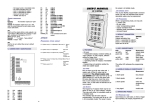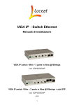
1
VERY IMPORTANT: For the electromagnetic lock, a 1N4005 diode should be connected as close as possible to the locks coil (if powered in DC) or a varistor (if powered in AC). up will be: - master code becomes 000000 the keypad works in monostable mode the relay activation time is 5s. RETEA LED stays lit. 9. CONNECTORS SIGNIFICANCE USERS MANUAL 1.2 THE KP 2M KEYPAD APENDIX PROGRAMMING OPTIONS SUMMARY **** (MASTER # 1 # (ADDRESS) # (NEW CODE) CODE) # 1.3 TRIGGER MODIFY/ ADD CODE) # 2 # (ADDRESS) # ERASE USER CODE **** (MASTER CODE) # 3 # (TIME) # 1.4 PROGRAMMING PROGRAMMING RELAYS While in programming mode, one may set: - 1 master code - 60 user codes - relays activation time - operating mode (monostable / bistable) ACTIVATING TIME **** (MASTER CODE) #0# RESET USERS CODES · · · · · · · · Pin NO1 Pin C1 Pin NC1 Pin N1 Pin N2 Pin GND Pin 12V Pin +Z1 button · Pin -Z1 button · Pin +Z2 · Pin -Z2 · TAMPER pins system relay relay relay (not used) (not used) connected to GND connected to +12V DC connected to Request to exit 1. FEATURES: - 60 users - 1 relay output - 1 NO trigger input for Request-toexit button. - 2 operating modes for relay: monostable / bistable - Programming and operation assisted by visible and audible signals connected to Request to exit (not used) (not used) should be connected to the alarm 2. LEDS SIGNIFICANCE LED POSITION SIGNIFICANCE green LED left relay state green LED right power on red LEDright 1.1 CODES KP2M can learn up to 60 user codes and 1 master code. ALl the 61 codes may be programmed. The default master code este 000000. Each code may have up to 1-6 digits between 0-9, and for the same code, the same digit may occur more than once. -4- INPUT This is a NO command input for the relay. On this input one may connect a Request-to-exit button. CODE **** (MASTER RELAY The keypad has a relay that may work either in monostable mode or in bistable mode. The activation time for this relay is programmable. The timing may be up to 1-99 s. (in monostable mode). The value 0 means the relay is in bistable mode. yellow LED mode alarm state right programming The yellow LED witnesses the programming mode. -1- 3. AUDIBLE SIGNALS SIGNIFICANCE SIGNAL Esc key on a PC keyboard). The entered codes may be classified as master code and users codes. The master code, comparing to the users codes, may program the keypad. The master code is always the code with the address 0 and may be modified but not erased. A valid code entry is signalized by three short beeps. An invalid code entry is signalized by a long beep (aproximately 1s.). SIGNIFICANCE 1 short signal key pressed 3 short signals valid code 2 short signals enter into programming mode 1 long signal invalid code 4. OPERATING MODES 4.1 MONOSTABLE 6. NOTES 1. The default master code is 000000. 2. The master code is always the code with the address 0. 3. The master code allows the access to the programming mode. MODE Upon keying in a valid code, or when the trigger input activates, the relay programmed as monostable will activate for the programmed period of time (1 - 99s). While the relay is still activated, one may key in another code. The relay timing may be extended to the double of the programmed period. 4.2 BISTABLE 4. All codes entries must be followed by # key. 5. Codes have 1-6 digits; into the same code the digits may repeat. 6. In case the master code is forgotten or doesnt seem to work, the keypad may be set to default (see chapter SYSTEM SET UP TO DEFAULT). 7. 2 short beeps confirm the enter in programming mode. 8. To enter programming mode press: **** (master code) # MODE Upon keying in a valid code, or when the trigger input activates, the relay will activate and will maintain this state until a valid code is entered. 9. To exit programming mode press *. 5. CODES ENTER A code may have 1-6 digits (0-9). The code enter should always be followed by the key # . So, to enter a code do the following: 1. key 1 followed by # modify/add new codes 2. key 2 followed by # erase user codes 3. key 3 followed by # set relay activating time 4. key 0 followed by # reset all user codes In the following: - the items to be set are in bold . - the procedure is written in normal type style. - the effect is in italics. digit [digit digit digit digit digit] # * Pressing key while entering a code is cancelling the digit pressed previously (it is the same effect as 7.1 CODES 1. TO -2- 2. TO ADD PROGRAMMING: YELLOW LED to exit programming mode press * 2. THE OPTION PROGRAMS THE RELAY ACTIVATION TIME codes address is expected: 0-60 press 3# keypad waits for the desired time (0-99s) to be entered to go back to step 1press * to go back to step 1press * CODES press 1 # 3. ADDRESS blinks fast 3. ENTER ENTER press (address) # blinks slowly+ 2 beeps the menu option is expected to be entered to exit programming mode press * blinks slowly blinks slowly THE DESIRED TIME press (time) # blinks slowly new code is expected to be entered goes back to previous step to go back to step 1press * NOTE: If the entered address is wrong and the # key was not yet pressed, the correct address may be entered. Upon pressing the # key, the last two entered digits will be considered. NOTE: If the entered value is wrong and the # key was not yet pressed, the correct valuemay be entered. Upon pressing the # key, the last two entered digits will be considered. The time should not always be entered as 2 digits. Ex: to set the time for 5 s., one may press simply: 5 #. If the activation time is set to 0, the relay is set as bistable. An y other value, different from 0, sets the relay as 4. KEY IN THE NEW CODE press (new code) # goes back to previous step blinks fast monostable. NOTE: If the entered code is wrong and the # key was not yet pressed, the new code may be entered subsequently. 7.4 USERS 7.2 ERASING 1. TO 1. TO USER CODES YELLOW LED press **** (master code) # CODES RESET YELLOW LED ENTER THE PROGRAMMING MENU press **** (master code) # ENTER THE PROGRAMMING MENU beeps is expected to be entered blinks slowly+ 2 beeps the menu option is expected to be entered blinks slowly+2 the menu option to exit programming mode press * 2. ERASING to exit programming mode press * CODES OPTION press 0 # goes back to previous step CODES OPTION press 2 # The programming menu has the following options: blinks slowly + 2 beeps the menu option is expected to be entered 2. ERASING 7. PROGRAMMING press **** (master code) # press **** (master code) # blinks slowly blinks fast codes address is expected: 0-60 to go back to step 1press * 8. NOTE: the address 0 is ignored. 3. ADDRESS When the master code is forgotten or it doesnt seem to work the keypad may be set up to default as follows: ENTER press (address) # blinks slowly goes back to previous step NOTE: If the entered address is wrong and the # key was not yet pressed, the correct address may be entered. Upon pressing the # key, the last two entered digits will be 1. power off the keypad. 2. open the case . 3. short cut (close) JP3 jumper 4. power on the keypad; all the LEDs will be lit. 5. press the * key, subseqently, five times. Any other key pressed cancel the set up to default procedure. 6. open the JP3 jumper. The default values set considered. 7.3 PROGRAMMING 1. TO SYSTEM SET UP TO DEFAULT THE RELAY ACTIVATION TIOME YELLOW LED ENTER THE PROGRAMMING MENU ENTER THE PROGRAMMING MENU -3-