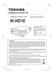
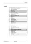
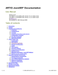
1
User manual – KH300 1、Preface 1.1 Preface ---------------------------------------1 1.2 Parts list---------------------------------------2 1.3 Notice------------------------------------------2 2、General 2.1 Brief feature----------------------------------2 2.2 Technical data-------------------------------2 2.3 Type definition-------------------------------3 3、Installation 3.1 Installation ambient------------------------3 3.2 Installation dimension---------------------3 3.3 Installation method------------------------4 3.4 Terminal description-----------------------5 3.5 Connection description-------------------5 3.5.1 Power connection-------------------5 3.5.2 Alarm output connection-----------5 4、Operation guide 4.1 Panel description--------------------------6 4.2 Key operation-------------------------------6 4.3 Configuration--------------------------------6 4.4 Parameter menu---------------------------7 4.5 Setting menu--------------------------------8 4.6 Example for setting of input channel-13 5、Screen description 5.1、Real time curve------------------------14 5.2、Multi-Channel display----------------15 5.3、Single Channel display--------------15 5.4、Bargraph display----------------------15 5.5、History Curve display----------------16 6、System configuration parameter setup 6.1、Common parameter--------------- - 16 6.2、Channel parameter-------------------17 6.3、Alarm parameter----------------------18 7、Function description 7.1、Digital filter------------------------------18 7.2、Alarm output----------------------------18 8、Data output and analysis 8.1、Data output------------------------------19 8.2、Data analysis software---------------19 9、Communication 9.1、Communication mode----------------21 1、Preface 1.1、Preface Please read this manual before you use the instrument. 1.2、Parts list Part name Main machine Bracket U disk CD Manual amount 1 2 1 1 1 y/n y y If U selected y y 1.3、Notice When you open the package,please check the appearance and the type to make sure it is the one you customized.If there are any problems please contact us immediately. Please understand the connecting and operation before the installation Please use the instrument in good condition.To avoid the dangerous you'd better not to open if by yourself,if there are any problems,please contact us at first. Don't use the organic solvents to clean the LCD screen or sharped by objects-extruded,it will damage the screen. The instrument should be detected once a year , if it is out of the range error, it mostly lead by the moisture ,dust or corrosion. You can clean and dry it to solve the above problem. If don't ,please contact our technicians. 2、General 2.1、Brief feature 5.6 inch TFT color LCD, wide visual angle, high lightness and contrast. Flexible setup function and a powerful statistics analysis function, easy operation Multiple channels input, photoelectric isolation for different channels TC and RTD input with nonlinear amendment, high precision and stable performance. Huge capacity storage and long recording time. The standard storage is 8 MB. It can be increased by as per customer’s requirement. 2.2、Technical data ● Input specification TC : K、S、E、J、T、B、N RTD : Cu50、Pt100、Cu100 Linear voltage : 0-5V、1-5V and etc. Linear current : 0-10mA、4-20mA and etc. (Need to connect with 500Ω or 250Ω precision resistor if no any speical requirment when placing order) ● Measure range K ( -50 ~ 1300℃ )、S ( -50 ~ 1700℃ )、T ( -200 ~ 350℃ ) 、E ( 0 ~ 800℃ )、 J ( 0 ~ 1000℃ )、B ( 300 ~ 1800℃ )、N ( 0 ~ 1300℃ ) Cu50 ( -50 ~ 150℃ ) 、Pt100 ( -200 ~ 600℃ )、Cu100 ( -50 ~ 150℃ ) 2 Linear input:-29999-29999, up to customer Measure precision : 0.2 grade ----- RTD, linear voltage, linear current, TC input and copper resistance or freezing point compensation 0.2%FS±2.0℃ ----- TC input and measure temperature for compensating cold terminal by meter interior component Respond time ≤1 s (setup filtering parameter is zero) Alarm function: high limit, very high limit, low limit, very low limit, up to 16 alarming output, can be used repeatly. ● ● ● ● ● Power consumption ≤45W Ambient temperature : 0-50℃ Ambient humidity : <85%RH Dimension : 144×144×250 Power : 165-240VAC,-15%,+10% / 50-60Hz 2.3、Type definition The types definition of recorders as followings chart : 3、Installation 3.1、Installation ambient 1.Ambient temperature : 0-50 2.Ambient humidity: 10%-85% (no dew) 3.Keep away from sunlight, steam, caustic gas and electromagnetism. 4.The thickness of steel plate for setting the meters must no less than 4mm, otherwise it will lead to shake. 5.Please keep the good venting around meters. 3.2、Installation dimension(unit:mm) Please see below chart: A B C Z X Y W H 144 144 32 218 138 138 >100 >100 3 3.3 Installation method 4 3.4 Terminal description 3.5、Connection description 3.5.1 Power connection Power connection: N-N, L-L, G-Gnd power voltage: AC165~240V 3.5.2 Alarm output connection There are 3 terminals for each alarm output: COM,NC,NO. COM ---- common terminal NC ---- normally close terminal NO---- normally open terminal The capacity of relay is 3A/220VAC,please use intermediate relay when the load is bigger than the rated power。 5 4、Operation guide LCD 4.1、Panel description Key The power switch Fix screw USB 4.2、Key operation :cursor right/down; :cursor left /up; :add; :subtract; :switch the interface; :enter ; digit select 4.3、Configuration When startup the instrument wait few seconds until the system will recall the last memory parameters. During this you can see on the display the soft version for your recorder . After initializing the recorder is in the recordein mode. you can scroll into the main screens. Using The name of the screen is displayed in the left-up corner as bellow : Real Time Curve Multi-Channel Single Channel History Curve PARAMETER Real Time Curve 6 Bargraph 4.4、PARAMETER menu Using go to PARAMETER screen. PARAMETER Tag. No Channel Color Hight-Hight : Low-Low : Press Press Hight : Low : or or to move cursor to the parameter you want to change. to change the value of parameter. Adjustable parameters in PARAMETER screen : Chanel Select the channel you want to change the settings. Press Color Change the color of selected channel in normal state ( no alarm). Press Hight-Hight Change the color of the selected channel in case of VERY HIGH alarm. Press Hight Change the color of the selected channel in case of HIGH alarm. Press Low_Low Change the color of the selected channel in case of VERY LOW alarm. Press Low Change the color of the selected channel in case of LOW alarm. Press Password Use and to insert the correct password and then press In this moment you have acces to SETTING screen. 7 4.5、SETTING menu SETTING 09-10-13 10:57:22 SYSTIME CHANNEL ALARM EXIT SAVE+EXIT Use or Then press to select the menu you want to change settings. to go into relevant menu: SYSTIME SYSTIME Address Baurate Parity Err.Act Œ‡€Þ Time Password Rec-Time Dis-Time Pnt-Time Press Press or or 1 9600 NULL 0 ENGLISH Change the date. Press Time Change the time. Press Password Single Channel 0 3275,1 / -3000,0 1 0 / -3000 Change the password. Press 8 History Curve OPEN / HH 0 / OK --- / LL --- / LL 2 .-2000 / -3000 .-2000 / LL --- / LL 3 3275,1 / -3000,0 OPEN / HH --- / LL 4 0 / -3000 5 .-2000 / -3000 6 3275,1 / -3000,0 7 0 / -3000 8 .-2000 / -3000 to move cursor to the parameter you want to change. to change the value of parameter. Adjustable parameters in SYSTIME screen : Date Err.Act. 0 / OK --- / LL .-2000 / LL --- / LL OPEN / HH --- / LL 0 / OK .-2000 / LL --- / LL --- / LL Rec-Time Change the recording interval. (s) Press Dis-Time Change the display trend refresh interval. (s) Press Pnt-Time Change the printing interval (valid only for recorders with print port). (s) Press Address Change the communication addres in case of RS485 network. Press Baudrate Change the baudrate in case of RS485 network. Press Parity Change the parity in case of RS485 network. Press Err.Act. Change the behaviour in case of alarm. Press Œ‡€Þ Change the menu language. Press Enter Back to SETTING menu. SETTING 09-10-13 10:57:22 SYSTIME CHANNEL ALARM EXIT SAVE+EXIT 9 Use or Then press to select the menu you want to change settings. to go into relevant menu: Channel Channel CopyFrom Input Decimal Disp.Hi Disp.Lo Filter Unit Channel CH1 K 1 100,0 0,0 0 ˚C Tag.NO C.jc. Adjust Low Cut Tot.Dec Total.K Multiple mA output 0,0 0,0 2 0,00 0,0 0,0000 0 Select the channel you want to change settings. Press Tag.NO Change the destination of the channel (as sensor no.). Press CopyFrom Copy the same settings from specified channel. Press Input Set the input sensor. Press Decimal Set the decimal places to be displayed. Press Disp.Hi Set the maximum limit of the graph (recommended value = 100). Press Disp.Lo Set the minim limit of the graph (recommended value = 0). Press Filter Set the filter time to this input. (s) 10 Press Unit Set the measurement unit. Press C.jc. Cold junction compensation. Press Adjust Calibration of input by adding this value. Press Low Cut Set the “0 to display” limit. Values lower than this value will force the display to 0. Press Tot.Dec. Set the TOTALISER decimal point. Press Total.K Set the TOTALISER multiplier constant for instantaneous value (k x CH1Value = TOTAL). Press Multiple Calibration of input by multiplying with this value. Press mAoutput Set the output channel for analogue output 4-20mA. Press Enter Back to SETTING menu. 11 Alarm Alarm Channel Action High Low Hi-High Lo-low Channel Value Diff. OutPut Select the channel you want to change settings. Press High Change the value of alarm in case of HIGH alarm. Press Value---- Change the value of HIGH alarm. Press Diff.---- Change the value of hysteresis for HIGH alarm. Press OutPut---- Change the Output relay for alarm. Press Low Change the value of the selected channel in case of LOW alarm. Press Value---- Change the value of LOW alarm. Press Diff.---- Change the value of hysteresis for LOW alarm. Press OutPut---- Change the Output relay for alarm. 12 Press Hi-Hight Change the value of the selected channel in case of VERY HIGH alarm. Press Value---- Change the value of VERY HIGH alarm. Press Diff.---- Change the value of hysteresis for VERY HIGH alarm. Press OutPut---- Change the Output relay for alarm. Press Lo_Low Change the value of the selected channel in case of VERY LOW alarm. Press Value---- Change the value of VERY LOW alarm. Press Diff.---- Change the value of hysteresis for VERY LOW alarm. Press OutPut---- Change the Output relay for alarm. Press Enter Back to SETTING menu. 4.6、Example for setting of input channel Change “K” type input to “T” type input . Press PARAMETER more times , until you see PARAMETER screen. Press 、 to move the cursor to the right password. Then press Password . Then press . You will see the SETTING screen 13 or to insert SETTING to move the cursor to Channel 、 Press menu. Press . Channel Channel Tag.NO CopyFrom Input Then press or to select the input. Then press more times until you move the cursor on Enter . SETTING more times to move the cursor to SAVE+EXIT Press 、 Press to go back to REAL TIME CURVE menu. . Real Time Curve 5、Screen description 5.1、Real Time Curve display Real time Real Time Curve Number of channel Real measurement Alarm state Curve display percentage time The measurement and real curve of six channels can display on one interface at same time. Press or to move cursor, press to switch the next interface. press Alarming state description: or “OK”:normal, no alarming “LA”:lower alarm limit “HA”:upper alarm limit “LL”:bottom lower alarm limit “HH”:top upper alarm limit. 14 to amend the channel number of curve. 5.2、Multi-Channel display Real time Multi-Channel Alarm state Unit Real time measurement Press to switch the next display. 5.3、Single Channel display Real time Single Channel Totalizer value The number of channel Real time measurement Press Press Press or to move cursor or to amend the channel number. Press to switch the next display. 5.4、Bargraph display Bargraph Press Press Press or to move cursor or to amend the channel number. to switch the next display. 15 to delet the Totalizer Value. 5.5、History curve History Curve Press Press Press or to move cursor or to amend the channel number or history time of the curve. to switch the next display. 6、System configuration parameter setup There are two kinds system configuration parameter: common parameter and channel parameter. Common parameter is the only system parameter or parameter which is suitable for all different channels. Such as time, date, recording interval, display interval. Channel parameter is the independent parameter for each channel. Such as input type, measure range, alarm etc. 6.1 Common parameter Default Parameter Range Description Date valid date value System real date Time valid time value System real time 000000 Password character System password is provided to prevent system parameter not be changed viciously. 1 Record 1~3600 (s) Record total time is longer when the interval time is bigger. And vice versa. When the variation of measured object is slow, this parameter can be set bigger, otherwise it can be set smaller. Mostly, this suitable value should be the half of measured variation time or smaller. 1~3600 (s) Graph refresh is slow when the interval time is big. The range of relevant time of curve is big too. And vice versa. interval 1 Display interval 0 Print interval 1-30000s The unit is “s” : It don’t print when the value is “0” 1 Local address 0~255 Local address must be difference when there are multi-communication. 9600 Baud rate 2400 、 4800 、 9600、19200 Language English, Chinese It is communication speed. The baud rate must be same as host computer (Such as PC) when there are multi-communication. Language switch 16 6.2. Channel parameter Default none Channel number of channel CopyFrom Range CH1~CH16 character CH1~CH16 Description the relevant channel of current parameter number Move the cursor to this menu and input the number , of channel which will be copied, then press the parameter of source channel will be copied to current channel. All the parameter include alarm parameter are same between source channel and current channel. After finishing setting, the number of channel will become to current channel no .automatically K、S、B、T、E、 _1_:remaining input type for TC J、N、_1_、Pt1b、 _2_:remaining input type for RTD Cu50 、 Cu1b 、 _3_:remaining input type for linear input 0-5V 、 1-5V 、 0-10mA, 4-20mA、 K Input 1 100 Decimal Disp.Hi 0-4 -20000 ~ 20000 0 Disp.Lo -20000 ~ 20000 0 Filter 0 ~ 99 ˚C YES Unit C.jc. character string NO (none) YES 0,0 Adjust -10000~ 10000 0.0 Low Cut -10000~ 10000 2 Tot.Dec. 0~ 4 The decimal point . The range of TC and RTD is constant. This parameter and upper limit of range can be used together to make real time curve. When there is linear input, the parameter also as the lowest limit of range. When the input signal is temperature, the value has a precision with 0.1. The range of TC and RTD is constant. This parameter and lowest limit of range can be used together to make real time curve. When there is linear input the parameter also as the upper limit of range. When the input signal is temperature, the value with precision up to 0.1. When the digitals flop because of the interference of input signal, the user can setup this parameter to make it smooth. The measured value is more stable when filter coefficient is bigger, but the response is slower if the filter is bigger. engineering unit This parameter only valid for the first channel. Setup it in other channels just control whether it use TC cold Junction temperature compensation. NO: none compensation, YES: (measure temperature component compensation) Cu50 (RTD Cu50 compensation) It can be used to correct the static error of measure value. In the mostly instance it is 0. It will be set when there has the static error or some special request. When the input signal is temperature the value has a precision with 0.1. It is used to select the values not significant . Bellow this value the displayed value is considered zero. Number of decimals for Totalizer. 0,00 Total.K 0~ 30000 Multiplier constant for Totalizer. 0,0000 Multiple -2,0000~ 2,0000 Multiplier for operation formula calibration. 0 mAoutput 0~ 16 Analogue output for appropriate input. 17 6.3. Alarm parameter Default 0,0 Parameter Number of channel Low 0,0 High 0,0 Lo-Low Range CH1~CH6 -20000 ~ 20000 -20000 ~ 20000 -40000 0,0 Hi-High -40000 0,0 Lower difference limit Upper difference limit Bottom lower difference limit Top upper difference limit Lower alarm output point 0,0 0,0 0,0 NULL return 0 ~ 2000 Description The relevant channel of current parameter Alarmworks when measured value is smaller than defined value. Alarm works when measured value is bigger than defined value. Alarm works when measured value is smaller than defined value. (bottom lower alarm) Alarm works when measured value is bigger than defined value. (top upper allarm Hysteresis return 0 ~2000 Hysteresis return 0 ~ 2000 Hysteresis return 0 ~ 2000 Hysteresis limit None Output 1~ 16 The lower alarm limit output position of relevant channel. None: no output The relevant output is invalid when the TC or RTD is open. The upper alarm limit output position of relevant channel. None: no output The relevant output is invalid when the TC or RTD is open. The bottom lower alarm limit output position of relevant channel. None: no output The relevant output is invalid when the TC or RTD is open. The top upper alarm limit output position of relevant channel. None: no output The relevant output is invalid when the TC or RTD is open. NULL Upper alarm output point limit None Output 1~ 16 NULL Bottom lower alarm limit output point None Output 1~ 16 NULL Top upper alarm limit output point None Output 1~ 16 7、Function description 7.1、Digital filter When the digitals flop because of the interference of input signal, the user can setup this parameter to make it smooth. The measure value is more stable when filter coefficient is bigger, but the response is slow if the filter is bigger. 7.2、Alarm output Lower alarm limit and bottom lower alarm limit Lower alarm Bottom lower alarm LA : Lower alarm limit LLA : Bottom lower alarm upper alarm limit and top upper alarm limit alarm stop alarm Upper alarm Top stop upper alarm limit HA : upper alarm limit HHA : Top upper alarm limit Hy : alarm different limitPV Hy : alarm different limit LA+Hy PV LLA+Hy LLALA HHA HHA-Hy HA HA-Hy 18 8、Data output and analysis 8.1、Data output 1、 2、 3、 Insure the file format of U disk is ‘FAT16’. If not, please format it to ‘FAT16’. Insure there is enough room in U disk, it must bigger than 8MB which is the standard meter storage. Please insert the U disk into USB interface which at the front panel of meter, the meter will create a file in U disk which be named according to current date such as 021008.dat, the data will be save in it. Please don’t take U disk out during the file storage process to avoid affecting the normal work of meter. If there is something wrong in the storage process, please take U disk out and confirm it meet above requirement of point 1 and 2. If there is something wrong with the screen display, please press refresh the display. 4、 to Please take U disk out when the ‘data output’ menu display OK. 8.2、Data analysis software 1、 Please insert the U disk into computer to analyze data. If you want to save the data please copy it to computer. 2、 Run the analysis software, Click “file” >> “open…” 3、 Select the data file. 19 4、Click ‘open’ menu, find the data of specified time, also can output the data. 5、Setup time and date and find the wanted data. 6. data output 20 9、Communication 9.1、The way of communication KH300 has serial communication. It communicate with computer by RS232 or RS485, the meter can be operated through computer, thereby achieve DCS control. Communication agreement apply MODBUS standard agreement, it has powerful compatibility and stable communication. Up to 255 meters can be connected on one communication bus line (the repeater is required) . Password = 000000 . MODBUS-RTU Asynchronous communication 21