1
instruNet
Users Manual
®
January 5, 1998
Manual Version 1.25
This equipment complies with the requirements in Part 15 of FCC Rules for a Class A computing device.
Operation in residential areas may cause unacceptable RFI interference.
Ch 1 Installation
Contents
Chapter 1 Installation
instruNet Family Overview
Overview
Controllers
Network Devices
instruNet Software
Computer Requirements
Constructing Your Network
Install as many controllers as desired
Install up to 16 Devices on each Network
Each Controller includes Timer I/O Channels
Each Controller includes one Terminator
Each Network Device includes one cable
You can purchase your own cables
Minimum Base System
Maximum Sample Rate
Turn power OFF when cabling
Large networks require external power supply
Hardware Installation
Software Installation
Windows/x86 Computer
Macintosh Computer
Verifying That Your Systems Is Working Properly
instruNet BASIC Software License Installation
1-1
1-1
1-1
1-2
1-2
1-3
1-3
1-3
1-3
1-4
1-4
1-4
1-4
1-4
1-4
1-5
1-5
1-5
1-7
1-7
1-7
1-8
1-10
Chapter 2 instruNet Tutorial
Record Waveforms in 7 Easy Steps
Digitizing Analog Signals into the Computer
The instruNet Data Tree
Explore Your World
The Network Page
The Probe Dialog
Channel Address
Working with Sensors
Working with instruNet BASIC
Working with Calibration, Different Scales, and Mapping
Working with Digital Filters
Working with Voltage Output Channels
Working with Digital I/O Channels
Working with Controller Digital Timer I/O Channels
Working with The Controller Time Since Reset Channel
Working with Multiple Controllers
Next Step
instruNet User's Manual
2-1
2-4
2-8
2-10
2-10
2-11
2-12
2-14
2-18
2-21
2-22
2-25
2-26
2-27
2-30
2-31
2-31
TC - 3
Ch 1 Installation
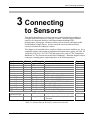
Chapter 3 Connecting to Sensors
Connecting a Sensor to instruNet
Sensor Reference
Single-ended Voltage Measurement
Differential Voltage Measurement
Bridge Ratio Voltage Measurement
Current Measurement
Resistance Measurement: Voltage Divider Circuit
Resistance Measurement: Bridge Circuit
Strain Gage Measurement: Voltage Divider Circuit
Strain Gage Measurement - Quarter Bridge
Strain Gage Measurement - Half Bridge (Bending)
Strain Gage Measurement - Half Bridge (Axial)
Strain Gage Measurement - Full Bridge (Bending)
Strain Gage Measurement - Full Bridge (Axial I)
Strain Gage Measurement - Full Bridge (Axial II)
Temperature Measurement (RTD) Voltage Divider
Temperature Measurement (RTD) Bridge Circuit
Temperature Measurement Thermocouple
Temperature Measurement Thermistor
Sensor Reference Footnotes
3-2
3-6
3-6
3-7
3-7
3-8
3-8
3-9
3-10
3-11
3-12
3-13
3-13
3-14
3-15
3-15
3-17
3-18
3-19
3-20
Chapter 4 A Tutorial For Programmers
Programming Overview
instruNet Function Call
Simple Format Functions
Digitizing
Support Functions
Interface Files
Programming Examples
instruNet Data Types
instruNet Macros
Example Code
Tutorial Summary
Getting Started
Working with any C compiler
Getting Started with Macintosh Symantec C/C++
Getting Started with Macintosh metrowerks CodeWarrior C/C++
Getting Started with Microsoft Visual Basic for Windows 95/NT
Getting Started with Microsoft C/C++ for Windows 95/NT
TC - 4
4-1
4-1
4-2
4-3
4-4
4-5
4-5
4-5
4-6
4-6
4-7
4-8
4-8
4-9
4-10
4-12
4-12
instruNet User's Manual
Ch 1 Installation
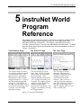
Chapter 5 instruNet World Program Reference
The Network Page
Overview
Surfing The Net
Modifying Fields
Channels
Turning A Channel On
Pull Down Menus
Saving Your Configuration
Reconnecting With A Changed Network
Buttons
The Record Page
Setting Up Channels
Setting Up Displays
Oscilloscope or Strip Chart
Setup Options
Saving Data
Trigger Options
Getting Ready to Digitize
Digitizing
If Your Sample Rate is Too Fast
Buttons
The Test Page
Buttons
The BASIC Page
Buttons
5-2
5-2
5-3
5-3
5-3
5-4
5-4
5-4
5-4
5-4
5-5
5-5
5-6
5-6
5-8
5-10
5-11
5-12
5-12
5-12
5-12
5-14
5-15
5-16
5-16
Chapter 6 Hardware Reference
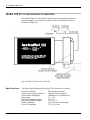
Model 200 PCI and 220 Nubus instruNet Controllers
Specifications
Model 230 PC-Card instruNet Controllers
Specifications
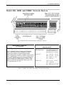
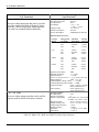
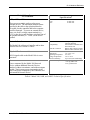
Model 100, 100B, and 100HC Network Device
Specifications
Model 300 Power Adaptor
Model 311 and 322 Power Supplies
Model 330 Electrical Isolator
6-2
6-2
6-4
6-4
6-5
6-5
6-9
6-10
6-11
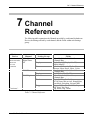
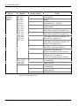
Chapter 7 Channel Reference
Channel Reference
7-1
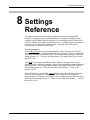
Chapter 8 Settings Reference
Settings Reference
instruNet User's Manual
8-1
TC - 5
Ch 1 Installation
Chapter 9 instruNet BASIC
Overview
Software License
BASIC Page
Buttons
Benefits
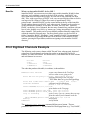
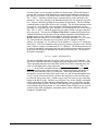
Print Digitized Channels Example
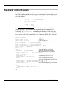
Feedback Control Example
Channel Setup and Calibration Example
File I/O Example
Programming Example
Mathematical Expressions
Logical Operators
Conditionals
Basic Functions
Round Off Functions
Statistical Functions
String Functions
instruNet Hardware
Trig. Functions
Temperature Conversion Functions
Numerical Constants
Base Keywords
Time Keywords
Debugging
Objects
Program Code
Commands
Pages & Buttons
Variables!
Strings$
Defines#
Object Database
Comments
Channel Address
Channel Lists
Text Files
BASIC Files
Startup.iBs
Version 1.25
Code Syntax
Command Line
[item1/item2/...]
Italics
(parameter)
"Text"
Math Expressions
\r and \t
Floating Point
Object Names
Object Management Commands
Append
Clear
TC - 6
9-1
9-1
9-1
9-1
9-2
9-2
9-4
9-5
9-6
9-7
9-8
9-9
9-9
9-9
9-9
9-9
9-9
9-9
9-10
9-10
9-10
9-10
9-10
9-11
9-11
9-11
9-11
9-11
9-11
9-12
9-12
9-12
9-12
9-12
9-12
9-12
9-12
9-12
9-13
9-13
9-13
9-13
9-13
9-13
9-13
9-13
9-13
9-14
9-14
9-14
9-14
9-14
instruNet User's Manual
Ch 1 Installation
Copy
Define
Delete
String$ = string items
Variable! = math expression
Programming Commands
Debug
End
For ... Next
Goto ... Label
If, elseif, else, EndIf
If (...) then ...
License
Loop
Synchronize
While (...) ... EndWhile
User Interface Commands
Alert
Beep
Delay
Erase
Print
Question
Page & Button Commands
NewPage
NewButton
Press
Select
Show/Hide page
Show/Hide button
Calibrate Hardware
Calibrate Gages
Calibrate Bridges
Calibrate VDividers
Calibrate Vinit
Calibrate Int1/Int2
Digitize
SetChannel
SetChannelBit
SetField
SetTrigger
Table
File Commands
Close
Create
Flush
Open
SetMasterDir
SetPointer
SetSize
instruNet User's Manual
9-14
9-14
9-14
9-15
9-15
9-15
9-15
9-15
9-15
9-15
9-16
9-16
9-16
9-16
9-16
9-16
9-17
9-17
9-17
9-17
9-17
9-17
9-18
9-18
9-18
9-18
9-18
9-18
9-18
9-19
9-19
9-19
9-19
9-19
9-19
9-19
9-19
9-20
9-20
9-20
9-20
9-20
9-21
9-21
9-21
9-21
9-21
9-21
9-21
9-21
TC - 7
Ch 1 Installation
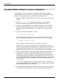
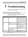
Appendix I Troubleshooting
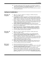
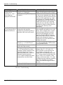
Identifying Symptoms and Possible Causes
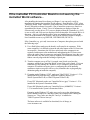
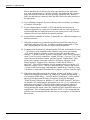
If the instruNet PCI Controller Board is not seen by the instruNet World Software
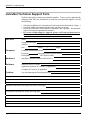
instruNet Technical Support Form
A-I-1
A-I-3
A-I-5
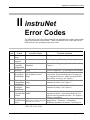
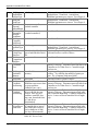
Appendix II Error Codes
Error Codes
A-II-1
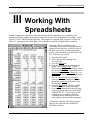
Appendix III Working With Spreadsheets
Overview
A-III-1
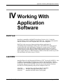
Appendix IV Working With Application Software
Working with DASYLab
Working with LabVIEW
Working with HP VEE
Working with MicroLab
Working with Origin
Working with TestPoint
A-IV-1
A-IV-1
A-IV-2
A-IV-2
A-IV-2
A-IV-2
Appendix V Working With instruNet Files
instruNet File Types
Reading instruNet Files From C
A-V-1
A-V-1
Manual by Glenn Weinreb and Stephen McCabe. Copyright © 1996-98 GWI.
instruNet® is a registered trademark of GWI. Manufactured in USA.
TC - 8
instruNet User's Manual
Ch 1 Installation
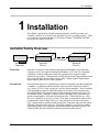
1 Installation
This chapter explains how to install instruNet hardware and software onto your
computer, and how to verify that your instruNet System is operating properly. With
new systems it is recommend that you first do the Chapter 1 Installation, and then
proceed to the Chapter 2 Tutorial.
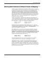
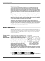
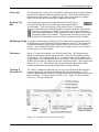
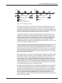
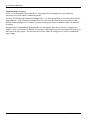
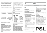
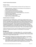
instruNet Family Overview
0-300 meters
instruNet
Controller
Network
Device
Network
Device
Overview
instruNet is a hardware and software product family that enables one to interface
computers such as the Apple Macintosh and Windows 95/NT x86 PC Compatible
computers to common laboratory and factory equipment for purposes of data
acquisition and control. instruNet utilizes a high speed network approach that is both
low cost and flexible for providing voltage inputs, voltage outputs, digital inputs,
digital outputs, and timer I/O to the computer.
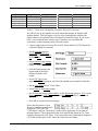
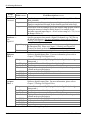
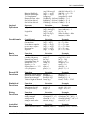
Controllers
Each instruNet Network is controlled by a Network Controller board that installs into
a computer. A different controller board is used with each common bus interface
(e.g. Nubus, PCI, PC-Card), yet they are all very similar internally. Each Controller
is an independent computer in itself that utilizes a powerful 32-bit microprocessor
and onboard RAM to control all aspects of data acquisition along its network. One
can install as many Controllers as desired, space permitting, since each controller
operates independently. Each network supports up to 32 Network Devices. Each
Device is a small box (e.g. 10cm x 12cm x 25cm) that is connected in a daisy-chain
configuration to form a chain of Devices. Each network can be up to 300 meters
long. All networks are anchored with an instruNet Terminator at the far end, and an
instruNet Controller at the near end. This makes instruNet a cost effective method
for designing large scale, high speed, multi-channel data acquisition systems. The
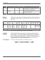
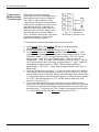
following table lists the instruNet Controllers described in this manual.
instruNet User's Manual
1-1
Ch 1 Installation
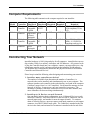
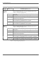
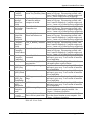
Model
200(s)
230(s)
220(s)
Controller
PCI Controller
Computer Required
Windows 95/NT x86 Compatible Computer
with PCI Rev ≥2.0 compliant, 32-bit, +5V
slot; or Macintosh with PCI Slot.
PC-Card
PC-Card
2" x 3"
Windows 95 x86 Compatible Computer with
Controller
Type II PCMCIA compliant ≥ v2.1 (or ≥ PCCard 95) PC-Card slot.
Nubus Controller
Nubus
7" x 4"
Macintosh with ≥ 7" Nubus Slot
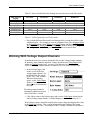
Table 1.1 instruNet Controllers described in this Manual
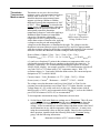
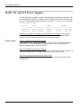
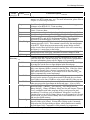
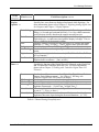
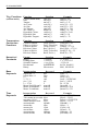
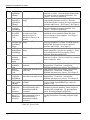
Network
Devices
Model
100
100B
100HC
Bus
PCI
Size
7" x 4"
Network Devices typically provide voltage input channels, voltage output channels,
digital inputs and digital outputs. The following Network Devices are described in
this manual:
Voltage Inputs
Voltage Outputs
# of
Absolute
# of
Write
Read-back
Digital
Channels
Range
Accuracy
Channels
Accuracy
Accuracy
I/O
16ch w/ +/- 5V
+/-2000µV
8ch with +/- 40 mV
+/- 3mV
8
screw
+/-.6V
+/-400µV
4mA/1KpF
Bidirectional
terminal +/-80mV
+/-75µV
Drive
I/O Bits
access +/-8mV
+/-40µV
Capability
Same as #iNet-100, yet with 16 additional BNC connectors for 16se voltage inputs.
Same as #iNet-100, yet with voltage outputs that have 15mA/.01uF drive capability.
Table 1.2 instruNet Network Devices described in this Manual
instruNet
Software
instruNet includes software to interrogate, test, configure, and do I/O with all
network channels. This includes an application program called "instruNet World";
drivers; interfaces to C, and Visual BASIC. instruNet World and the instruNet
Driver can configure all I/O channels, store your settings, view digitized data in real
time, stream data to disk, and scroll through your waveform post-acquisition.
instruNet software runs on both a PC and a Macintosh.
Free Updates
Free software and manual updates are available on the web at:
www.instrunet.com
1-2
instruNet User's Manual
Ch 1 Installation
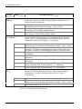
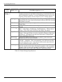
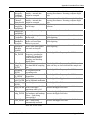
Computer Requirements
The following table summarizes the computer required to run instruNet:
Model
200(s)
200(s)
230(s)
220(s)
Computer
OS
RAM
HD
Slot
Controller Required Required Required Required
Required
PCI
IBM PC or
Windows ≥ 4MB
≥ 6MB free PCI Slot, ≥6.8", Rev
Controller
Compatible 95/NT
≥2.0 compliant, 32-bit,
≥ 80486
+5V
PCI
68K w. math System
≥ 4MB
≥ 6MB free PCI Slot, ≥6.8"
Controller
coprocessor ≥7.0
or Power
Macintosh
PC-Card
IBM PC or
Windows ≥ 4MB
≥ 6MB free Type II PC-Card Slot
Controller
Compatible 95
with ≥ v2.1 PCMCIA
≥ 80486
compliant card services
Nubus
68K or
System
≥ 5MB
≥ 6MB free Nubus Slot, ≥6.8"
Controller
Power
≥7.0
Macintosh
Table 1.3 Computer Requirements for instruNet Controllers
Constructing Your Network
instruNet hardware is 100% plug and play for all computers. instruNet does not use
dip switches, DMA, low memory, interrupts, and I/O addresses. All you need to do
is plug the Controller board into your computer, connect your network devices, slap
a terminator onto the end of your network and run the instruNet World software.
The instruNet driver automatically determines the physical locations of all installed
Controllers and Network Devices.
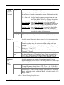
Please keep in mind the following when designing and constructing your network:
1 . Install as many controllers as desired
The number of available slots determines the number of controllers (i.e.
networks) that can be installed, and simultaneously run, on one computer. The
software numbers each controller in the order that they are found in the computer
("netNum" ranges from 1 to # of Controllers). Each controller manages its own
network of devices. In most cases, only one controller is necessary. The
advantage of multiple controllers is that each is its own real-time machine, and
more controllers can do more things simultaneously.
2 . Install up to 16 Devices on each Network
One can attach, in daisy-chain configuration, up to 16 Network Devices to each
instruNet Controller. Each Network Device has two DB-25 connectors, one for
network input (male), and another for network output (female). To connect a
chain of Network Devices, one must connect each input connector to each output
connector via a DB-25 Male/Female cable. The Controller is attached to the first
device in the chain, and an instruNet Terminator is attached to the far end of the
instruNet User's Manual
1-3
Ch 1 Installation
chain. Due to the male/female polarization, the network cannot be installed
incorrectly with instruNet Male-Female cables.
3 . Each Controller includes Timer I/O Channels
Each Controller (except iNet-230 PC-Card) provides 10 Timer I/O channels.
Each channel can be programmed as a digital input, digital output (0V/4V TTL
compatible), clock output, or period measurement input.
4 . Each Controller includes one Terminator
One instruNet Terminator must be installed at the end of each network chain.
This terminator mates with the output connector of the last device. instruNet
Controllers include an instruNet Terminator, therefore they do not need to be
purchased separately. Caution: Do not use a SCSI Terminator in place of an
instruNet Terminator -- they are different.
5 . Each Network Device includes one cable
Each instruNet Network Device is shipped with one 10foot DB-25 Cable
Male/Female cable for purposes of configuring your network.
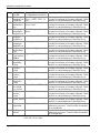
6 . You can purchasing your own cables
If you want a specific cable length, you can purchase your own DB-25 male to
DB-25 female, shielded, wired point-to-point (i.e. pin X to pin X) cables. We
recommend 24 gauge wire for > 4 meters; however 28 gauge is fine with ≤4m.
Twisted pairs are recommend for >4 meters with the following wires twisted: 1
& 14, 2 & 15, 3 & 16, 4 & 17, 5 & 18, 6 & 19, 7 & 20, 8 & 21, 9 & 22, 10 &
23, 11 & 24, 12 & 25 (these are physically next to each other in the connector).
A supplier of high quality DB25M/DB25F instruNet compatible cables is:
Global Computer Supplies
11 Harbor Park Dr. Dept RC
Port Washington, NY 11050
Tel 800-845-6225 or 516-625-6200
Fax 516-625-6683
www.globalcomputer.com
Global
Part #
#RCC91445A
#RCC91445B
#RCC91445C
#RCC91445D
#RCC91445E
Description
DB25m-DB25f
DB25m-DB25f
DB25m-DB25f
DB25m-DB25f
DB25m-DB25f
Length
6ft
10ft
15ft
25ft
50ft
#RCC4067A
#RCC4067B
#RCC4067C
DB25m-DB25f
DB25m-DB25f
DB25m-DB25f
#RCC4067X-ft DB25m-DB25f
Low
Cap
no
no
no
no
no
# of
Shields
double
double
double
double
double
100ft
150ft
250ft
yes
yes
yes
single
single
single
any
yes
single
A supplier of high quality twisted pair, low capacitance, double-shielded cable
without connectors is Belden, Inc. The following is an outstanding cable choice:
Belden Cable Part #8112; Low Capacitance, RS-485/RS-232 cable; available in
100ft, 500ft, and 1000ft lengths; 12.5 Pairs, with copper braided shield; 24 gage
wire; 41pF/meter between pairs; 72pF/meter between a wire and the shield;
78ohms/killometer wire resistance.
1-4
instruNet User's Manual
Ch 1 Installation
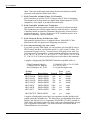
7 . Minimum Base System
One Controller and one Network Device is all you need to purchase to digitize
waveforms, save them to disk, and view them.
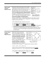
8 . Maximum Sample Rate
As the physical length of the network increases, the maximum aggregate data
acquisition sample rate decreases from 166Ks/sec maximum with a short network
(e.g. 5 meters) to 4.15Ks/second aggregate with a long network (e.g. 300
meters).
This maximum aggregate rate includes both input and output channels. For
example one instruNet network could support two voltage input channels and
two voltage output channels at a maximum rate of 41.5Ksamples/sec for each
channel (i.e. 166Ks/sec throughput). The same network would allow 4 channels
of voltage input to be acquired at 41.5Ks/sec per channel. The maximum
aggregate rate can be increased by installing additional instruNet networks and
controllers. For example, two controllers could support 332Ks/sec aggregate
throughput if run simultaneously.
When the instruNet powers up, it empirically tests (i.e. it test the cable
impedance) of the network to determine its maximum throughput rate (i.e.
4.15K/sec to 166Ks/sec). The maximum rate is decreased by: additional network
devices, longer aggregate network cable length, non-twisted pair cables, and
thinner cable wire (e.g. 28 gauge instead of 24 gauge).
9 . Turn power OFF when cabling
Always turn the computer and powered Network Devices Off before adjusting
network cables.
10. Large networks require external power supplies
The instruNet network cable provides power from the computer to the external
Network Devices. As the number of devices increases (more current drawn),
and the cable lengths increases (more voltage drops), it becomes increasingly
necessary to add an external power supply for the Network Devices. We
recommend adding an external power supply if your cable is > 50 meters, or for
every 4 Network Devices after your 3rd Device. In other words, only add an
external power supply if you have more than 3 network devices, or if your
network is longer than 50 meters.
Hardware Installation
To install an instruNet network, please:
1.
2.
3.
4.
5.
Read the previous "Constructing your Network" discussion.
Turn OFF your computer.
Turn OFF all powered devices connected to your network.
Touch bare metal on your computer to discharge personal static electricity.
Remove the cover from your computer to gain access to the card slots, as
needed.
6 . Remove the small I/O fence cover from the back of your computer, as needed.
instruNet User's Manual
1-5
Ch 1 Installation
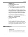
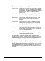
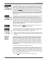
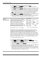
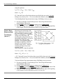
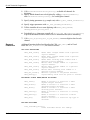
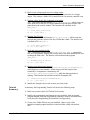
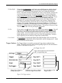
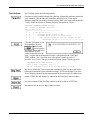
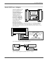
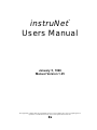
7 . If you require access to an available Controller Digital/Timer I/O Channel, run a
34-wire ribbon cable from the Controller's 34pin header connector, out of the
computer, any way you can (e.g. through another slot opening), to the breakout
of your choice (e.g. a screw terminal block), as illustrated below:
Figure 1.4, Installing an instruNet Controller into a Computer
8 . Install the instruNet controller(s) into the computer's expansion slot(s). If working
with a PCI Card, make sure the Controller connector is well seated and inspect this
connection with a strong light to make sure the printed circuit board fingers are
aligned with their mating connector pins.
9 . Bolt the board metal I/O fence to the computer, as needed (some computers do
this). Please skip this step if tightening this bolt causes the card to not seat well
in its connector.
1 0 . Put the cover back onto the computer, as needed.
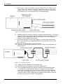
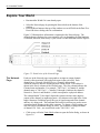
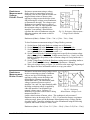
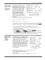
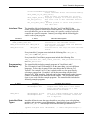
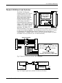
1 1 . Attach the external instruNet Network Devices in a daisy chain configuration, as
illustrated below.
Figure 1.5, instruNet Network
12. Tighten all DB-25 thumbscrews until lightly snug.
1 3 . Install an instruNet Terminator on the end of each network.
1 4 . It is recommended that the user attach the instruNet instrumentation ground
(i.e. instruNet box and instruNet GND screw terminals) directly to Earth
ground with a 16gauge wire from the left-most GND screw on the instruNet
box, to the closest Earth ground (e.g. screw next to power socket). This will
reduce the chance of RFI coupling into the instruNet ground, and is required if
the user wants to meet EC and FCC RFI guidelines.
1-6
instruNet User's Manual
Ch 1 Installation
15. If working with an iNet-230 PC-Card, attach an external power supply (e.g.
iNet-311 or 322) to the PC-Card 5pin DIN connector. This supplies power to
the external network devices (i.e. not the PC-Card itself).
1 6 . Turn the computer power ON and then Turn ON all powered devices attached
to the instruNet network.
Software Installation
Windows 95
Computer
1 . Make sure you are on a Windows 95 computer (≥ 80486) with at least
4MB of ram (8MB is better).
2 . If reinstalling new software over Version ≤1.22 software: Run The "System"
Control Panel, select "Device Manager", select "View Devices by connection",
expand "PCI bus", if you see "? PCI Card" select it & press the Remove button,
and exit "System" Control Panel. Do not install a PCI card driver at this time.
3 . Run the "SetupEx.exe" Windows installer program. This creates an instruNet
directory, installs many files into it, creates an instruNet program group, installs
"Windows\System\Inet32.dll", installs "Windows\ System\Inet95.vxd", and
installs "WindowsNT\System32\drivers\inet.sys".
4 . Turn the computer off, install the instruNet pci card, attach the instruNet
network devices, attach the instruNet terminator, tighten the thumbscrews, and
then power the computer back on.
5 . It may ask you for a PCI Card Driver on boot-up. Navigate via the Browse
button to "Program Files \ instruNet \ Win95 iNet PCI Driver \ inet95.inf".
6 . Run the "Start > Programs > instruNet > instruNet World" application in the
"instruNet" folder to operate and test your instruNet hardware and software.
7 . If you hit a problem, please proceed to Appendix I.
Windows NT
Computer
1 . Make sure you are on a Windows NT computer (≥ 80486) with at least
4MB of ram (8MB is better).
2 . Turn the computer off, install the instruNet pci card, attach the instruNet
network devices, attach the instruNet terminator, tighten the thumbscrews,
power the computer back on, and log in as the "Administrator".
3 . Run the "SetupEx.exe" Windows installer program. This creates an instruNet
directory, installs many files into it, creates an instruNet program group, installs
"Windows\System\Inet32.dll", installs "Windows\ System\Inet95.vxd", and
installs "WindowsNT\System32\drivers\inet.sys".
4 . Reboot the computer and log in under any account.
5 . Run the "Start > Programs > instruNet > instruNet World" application in the
"instruNet" folder to operate and test your instruNet hardware and software.
6 . If you hit a problem, please proceed to Appendix I.
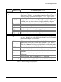
Macintosh
Computer
1 . Insert the instruNet Macintosh disk into your computer.
2 . If the items on the disk are compressed (i.e. the file has a ".sea" or ".sit" suffix),
uncompress it by double-clicking on it's ".sea" file and telling the computer to
place the decompressed folder on your hard disk.
3 . Copy a driver file from the "instruNet" folder on your hard disk into the
Extension folder, within the System folder. Several driver files are provided.
Please refer to the table below for the Driver that is most appropriate for your
computer. For example, on a Power Macintosh 7200 computer, one would
place a copy of the "instruNet Driver (ppc)" file into the Extensions folder.
instruNet User's Manual
1-7
Ch 1 Installation
Computer
Power Macintosh
68K Macintosh w Floating Point Co-Processor
Table 1.4, Macintosh Driver files
Appropriate Driver File
instruNet Driver (ppc)
instruNet Driver (68K & FPU)
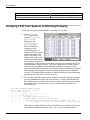
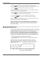
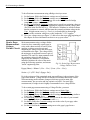
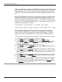
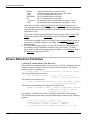
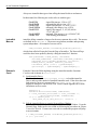
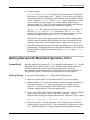
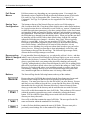
Verifying That Your System Is Working Properly
Verify that your hardware and software is working in 5 easy steps:
1 . Run the "instruNet
World" application
program ("instruNet
World Mac" on
Macintosh, and
"instruNet World
Win32.exe" on a
Microsoft Windows
computer), in the
instruNet directory. A
window will open, similar
to what is pictured to the
right. If necessary, you
might need to click on the
Network tab at the bottom
of the window to select the
Network page. If this window opens, then you know your instruNet driver file
is installed and working correctly. The list of channels shown in the window's
table will vary, depending on what instruNet hardware is connected. If the
instruNet window does not appear, then check the Software Installation section at
the beginning of this chapter to make sure that the software has been installed
correctly. If it appears that the software is installed correctly but not functioning
properly then see Appendix I Trouble Shooting.
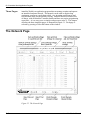
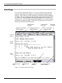
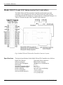
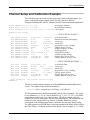
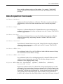
2 . Press the Test tab at the bottom of the window to select the Test page, and then
press the Search button at the top of the window. A report will print that lists
the controllers and network devices that are currently installed on your computer.
For example, the report below shows one Controller, and one Model 100
Network Device.
instruNet HARDWARE SEARCH RESULTS:
Date & Time: 10/2/1997, 12:12:41
Net Dev Mod Device
---------------------------------------0
0
0 Mac OS Ver 7.5.3
0
0
1
instruNet Driver Version 1.24
0
0
1
instruNet BASIC license 31-048353-62581
1
0
1
Nubus Controller #iNet-220 (slot #13, 4000KBD, 6us, 94%)
1
1
1
Device #iNet-100 (SN37532, Cal 9/28/1997, Rev 4, 30.99C, 6us, 17mA)
If this does not match what you believe is installed on your network, then check
your hardware installation (cables, power, etc). Also, it is possible that the
1-8
instruNet User's Manual
Ch 1 Installation
instruNet Driver is older than the devices on your network, which means you
need the latest driver that recognizes these new devices. The instruNet Driver is
always listed as the 1st installed item.
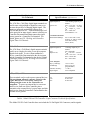
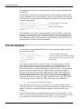
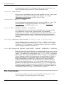
3 . Press the Test button at the top of the window to test your controllers and
devices, and to report any problems if found. The duration of the test can vary
from 1 to 120 seconds depending on the size of the networks, and the speed of
the computer. If no problems are found, a report similar to the one below is
printed in the window:
INSTRUNET QUICK TEST RESULTS:
Date & Time: 10/12/1995, 12:53:23
We ran 0.510029 million tests and did NOT hit 1 error.
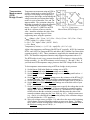
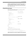
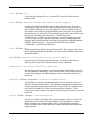
4 . Press the Big Test
button to run an
exhaustive test. An alert
similar to the one on the
right will appear to
communicate that the
computer will test all
instruNet hardware until
there is an error, or until you press the mouse button down. It will test your
network(s) all night long if you let it. Press OK to begin the Big Test. Wait 20
seconds or longer. If an error occurs while testing, an alert will appear and the
error message will also be printed in the window. Refer to Appendix II instruNet
Error Codes for more information on error codes, and Appendix I Trouble
Shooting for tips on de-bugging if necessary. If no error alerts appear, and you
want to stop the test, press the mouse button down and hold it down until the an
alert appears announcing the end of the test. Click OK to exit this alert. The test
results are printed in the window, in a format similar to what is shown below:
INSTRUNET BIG TEST RESULTS:
Date & Time: 11/7/1995, 15:53:19
We will run an exhaustive test on all instruNet hardware until
you mouse down (hold it down), or we hit an error.
We ran 2.170272 million tests and did NOT hit 1 error.
Big Test is identical to Test, except it runs for a longer period of time and is
useful at finding intermittent problems that only occur once every minute, hour,
or day. Big Test can be run overnight for extensive testing of all hardware.
5 . You are done! Your instruNet hardware and software is installed correctly and
running beautifully. Please proceed to Chapter 2, Tutorial to learn more.
instruNet User's Manual
1-9
Ch 1 Installation
instruNet BASIC Software License Installation
The instruNet "s" series controllers (i.e. iNet-200s, 220s and 230s), and the
instruNet BASIC License, #iNet-350, all include a license to the instruNet BASIC
Software. To register this liscense and enable this feature, one must:
1 . Install the standard instruNet software, as describe in the previous pages of this
chapter.
2 . Run the "instruNet World" application program (e.g. in the instruNet
directory) and then press the BASIC tab at the bottom of the window.
3 . Locate your instruNet BASIC License number included with the #iNet-200s,
#iNet-220s, #iNet-230s, and #iNet-350. This is printed on a sheet of paper
entitled "instruNet BASIC Software License" and is in a "zz-ssssss-yyyyy"
format.
4 . Type the following into the BASIC window:
License zz-ssssss-yyyyy
substituting the number printed on your license document for the zz-ssssssyyyyy. For example, if your license was 23-012345-54321, you would type:
License 23-012345-54321
into the window. Please do not place a space before or after the "-".
The license is in a zz-ssssss-yyyyy format, where ssssss matches the serial
number of your controller card. The license for each controller card is unique. If
you purchased instruNet BASIC #iNet-350, you will need to contact your
supplier to make sure you get a license number that matches your controller card.
5 . Press the Execute button. An alert should appear notifying that the license was
accepted and was stored in the Operating System directory, in a file called
"iNetLcns.txt", within your computer. You will not need to do this operation
again on this computer, provided the current OS directory stays in service. To
view the instruNet BASIC license number installed on a computer, press the Test
tab at the base of the window and then press the Search button to print out the
license number.
You have now enabled the powerful instruNet BASIC feature. If this feature
was not enabled, BASIC code would still execute, yet in demo mode where data
read from instruNet hardware is simulated.
6 . After learning about instruNet via Chapter 2 Tutorial, we recommend venturing
on to Chapter 9, instruNet BASIC, to learn more about this powerful feature.
1 - 10
instruNet User's Manual
Ch 2 instruNet Tutorial
2
instruNet
Tutorial
This chapter is a step-by-step tutorial that shows the user how to navigate within the
world of instruNet. Controlling instruNet hardware can be done manually though
the instruNet World application program, or through the programming languages
Visual Basic and C. This chapter deals exclusively with the easy-to-use application
program instruNet World application program while Chapter 4 covers programming
languages. The instruNet World allows you to set up and probe your network,
record waveforms, save them to disk, load them from disk, and view them post
acquisition.
Record Waveforms in 7 Easy Steps
This section explains how to record waveforms in several easy steps.
1.
Install your hardware and software per instructions in Chapter 1
If your instruNet World hardware and software is not installed, please install it
now, as described in Chapter 1.
2.
Run the instruNet World application program.
Locate the instruNet world application program within the instruNet folder on
your hard disk and then:
Win 95/NT:
Macintosh:
3.
Double-click on "instruNet World Win32.exe",
or run "Start > Programs > instruNet > instruNet World".
Double-click on the "instruNet World Mac" icon.
Select the Network Page.
instruNet World offers several Pages: Record, Network, and Test. Click on
the Network tab at the bottom of the window to select the Network page. The
Network tab will inverse black to indicate the Network page is selected.
Click here to select the Network Page
instruNet User's Manual
2-1
Ch 2 instruNet Tutorial
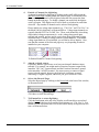
4.
Enable a Channel for digitizing.
A channel is enabled for digitizing by clicking on the small cell between the
addr and Value Input columns within the Network page, as illustrated below.
Once enabled, the channel will be digitized when the user presses the Start
button on the Record page. To disable a channel, one must click the digitize
on/off cell again. This digitize on/off cell is black or red when On, and white
when Off. Any number of channels can be selected for digitizing.
Please enable two voltage input channels (e.g. "Ch1 Vin+" and "Ch4 Vin+" on
the Model 100) for digitizing, as illustrated below. Voltage input channels are
typically labeled ChX Vin+ or ChX Vin-. These work identically when doing
single-ended voltage measurement (i.e. read a voltage between an input
terminal and ground), and are used as a pair when doing differential voltage
measurement (i.e. reading a voltage between 2 input channels). If instruNet
voltage input hardware is not installed, you will not be able to digitize. Also,
note that the contents of the Network page may vary depending on what is
installed on your computer.
To Enable/Disable a Channel for digitizing
5.
Attach a signal source.
If possible, attach a signal source to at least one channel's hardware input
terminal. For example, one might attach a Function Generator output to the
instruNet "Ch1 Vin+" input terminal, and the Function Generator's ground
to the instruNet "AGND" terminal. It is not necessary to connect a signal
source to do the tutorial, however, the displayed waveforms are more
interesting if a signal is applied; otherwise, you get a flat line at 0Volts.
6.
Select the Record Page.
Select the Record page by clicking on the Record tab at the base of the window,
as illustrated below.
Click here to select Record Page
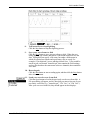
7.
2-2
Tell instruNet to start digitizing.
Click the Start button at the top of the window to tell instruNet to record and
display channels that have been enabled for digitizing (e.g. "Ch1 Vin+"). You
should see your waveforms move across the screen as they are digitized in realtime, as illustrated below.
instruNet User's Manual
Ch 2 instruNet Tutorial
8.
Tell instruNet to stop digitizing
Click the Stop button to stop the digitizing process.
9.
Save your waveforms to disk
Click the Save button to save your waveforms to disk. When the save
dialog appears, type a name and choose a convenient location to save the
data. Saving does not specify a file name, but rather a folder name in
which all acquired waveforms and a preferences file are saved. For
example, if you digitized 2 waves and then clicked Save, 3 files would be
stored in your: one named "instruNet.prf" that contains the Field settings,
and two files that have the same name as the two channels, that contain the
wave data.
1 0 . Record again
Click the Start button to start recording again, and then click the Stop button
after a few moments.
1 1 . Load your saved waves from disk
Click the Open button to load in the previously saved waves from disk. A
File open dialog will appear, and it is here that you must select one of your
previously saved files (e.g. "instruNet.prf", "Ch1 Vin+" or "Ch4 Vin+").
After your waves are loaded in, they should appear in their displays .
instruNet User's Manual
2-3
Ch 2 instruNet Tutorial
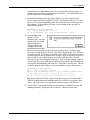
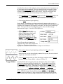
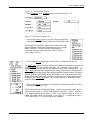
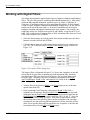
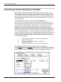
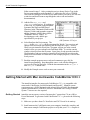
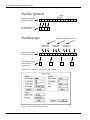
Digitizing Analog Signals into the Computer
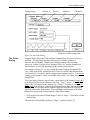
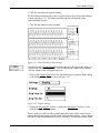
The Setup button at the top of the Record page opens a dialog box that effects the
manner in which waves are recorded.
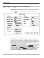
• Click the Setup button to open the Setup dialog, as illustrated in Figure 2.1.
Figure 2.1 The Setup Dialog
The Setup dialog is used to set the base sample rate, the number of points to be
acquired per Scan, the number of Scans to be acquired and the recording mode (i.e.
oscilloscope or strip chart recorder). All instruNet Networks are set up with one
base sample rate (i.e. number of points digitized per second) and individual channels
can have sample rates less than or equal to the base sample rate. This allows, in
effect, each channel to have its own sample rate.
The Sample Rate field sets the base sample rate. The Pts Per Scan field determines
the amount of data to be collected in each Scan. The No. of Scans sets the number of
Scans to be acquired. The Scan Mode popup has three choices: Strip Chart,
Oscilloscope, and Oscillo Queued. Strip Chart is selected for continuous strip chart
recorder mode and Oscilloscope or Oscillo Queued are selected for oscilloscope
mode. Refer to the Oscilloscope or Strip Chart section of Chapter 5 for a full
description of these modes. The Digitize field is used by programmers.
2-4
instruNet User's Manual
Ch 2 instruNet Tutorial
instruNet Networks are self-configuring and on startup determine the maximum rate
at which data can be transferred. This rate is displayed after pressing the Timing
button, in the Network BPS field, in units of bits per second. 4 million bits per
seconds is the fastest, and 100Kbps is the slowest. This rate slows down with
networks that have many Devices and long network cables (i.e. >100ft).
• Select Oscilloscope in the Scan Mode popup and set the Pts Per Scan field to 100.
100 points at 1000s/sec will take .1 seconds to acquire. Leave the rest of the
Dialog in its default settings, and click OK to return to the Record Page.
• Click the Start button to begin digitizing.
Notice how 0.1 second long waveforms continuously appear on the screen, in a
manner similar to an Oscilloscope. Before, we were in Strip Chart mode where these
segments were continuous with respect to each other. We are now in Oscilloscope
mode. To learn much more about digitizing, please refer to the Record page
discussion in Chapter 5, instruNet World Reference.
• Click the Stop button to stop
digitizing, and then click on the top
display's channel name label at the
right edge of the display. The
Display dialog will open. Choose
General in the Settings popup. Enter
the value 20 in the % samp rate field
as shown to the right and press OK.
This will cause the top channel to be
digitized at 20% of the master sample rate,
or 200s/sec. The channel in the lower
displays will continue to run at the master sample rate of 1000s/sec.
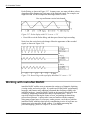
• Click the Start button to begin digitizing, and then click Stop after a few
moments.
Notice how the wave in the top display contains fewer points, due to its reduced
sample rate, as illustrated to the left.
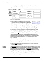
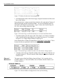
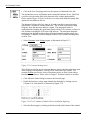
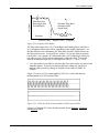
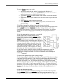
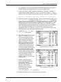
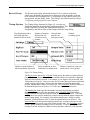
• Click the Setup button at the top of the Record page, and then click the Trigger
button to open the Trigger dialog, as shown in Figure 2.2.
Trigger Modes
instruNet World allows triggering from any channel on either a low-to-high or
high-to-low transition through a threshold value. The threshold is specified in
the Thresh EU field, and the trigger direction is specified in the Slope field (i.e.
low-to-high, or high-to-low). The channel to trigger from is specified by its
network address in the Trig Net#, Trig Dev#, Trig Mod# and Trig Chan# fields.
Three trigger types are allowed, as specified in the Trigger field: Off, Auto and
Norm. If Off is selected, data acquisition begins as soon as the Start button is
pressed in the Record Page. If Auto is selected, data acquisition begins after the
trigger criteria is met, but if the trigger condition is not met within a second or so,
instruNet User's Manual
2-5
Ch 2 instruNet Tutorial
the recording begins anyway. If Norm is selected, instruNet waits until the
trigger condition is met, indefinitely of necessary.
Fig 2.2 The Trigger Dialog
• Enter the address of a channel to trigger from into the
Trig Net#, Trig Dev#, Trig Mod# and Trig Chan# fields.
If you are not sure of a channel's address, go back to the
Network Page and look at the Channel and Addr column
for the channel you want to trigger from. The address for the two channels shown
in the above figure would be {1,1,1,1} and {1,1,1,4}. For example, if you
wanted to trigger from channel Ch4 Vin+, you would enter the following values:
1 into Trig Net #, 1 into Trig Dev#, 1 into Trig Mod#, and 4 into Trig Chan#.
• Select Auto in the Trigger popup, type a reasonable threshold voltage into the
Threshold EU field (e.g. 1V) and then select Rising or Falling in the Slope
popup. Click OK to exit the Trigger Dialog, click OK to exit theSetup Dialog
and then click the Start button to begin recording.
The waveforms should appear on the screen, with the beginning of each Scan
synchronized to the trigger event. If the signal applied to the trigger channel does
not periodically cross the threshold voltage, Auto trigger will digitize anyway
every second or so.
• Press Stop when you are done acquiring.
To learn more about Triggering, please refer to the Record page discussion in
Chapter 5.
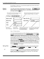
• Click the Setup button at the top of the Record page to open the Record Setup
dialog, as shown in Figure 2.1.
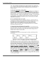
Display
Options
2-6
The Horiz Scale field sets the display horizontal scale in seconds-per-division. If set
to Auto, instruNet picks a horizontal scale that is appropriate based on the sample rate
and number of data points being acquired. The Disp Height field sets minimum
height of each display in the Record page, in pixels. If the number of waveforms
being digitized is greater than the available space on the screen, only a subset are
displayed, and a vertical scrollbar selects that set. The Plot popup is used to set the
drawing mode to plot Dots or Lines (i.e. light one pixel for each data point, or
connect these data points with lines), and the Grid popup selects whether or not to
overlay a grid on each display.
instruNet User's Manual
Ch 2 instruNet Tutorial
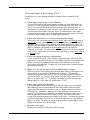
Digitize Into
Ram or File
The Digitize Into popup has 2 primary settings: To Ram Buffer, which saves
digitized data into RAM; and To File, which digitizes data directly to disk. If
Digitize Into is set to To File, instruNet automatically prompts the user for a
folder name every time a recording session is initiated with the Start button. The
waveforms are then saved to this folder while they are recorded. One can then
scroll through these long disk-based waveforms (e.g. 20M points per channel)
via the horizontal scrollbar. Any waves saved to disk using the To File option
can be opened and scrolled through with the Record Page's Open button.
The File Type field determines the file format for the saved data, and is set to one
of Binary, Binary Merge, Text, or Text Merge. For a detailed description of each
format, please see Appendix V, Working with instruNet Files.
• Select Lines in the Plot popup, select Off in the Grid popup, select "Strip Chart" in
the Scan Mode popup and, set the Pts per Scan field to 10000 to set the buffer size
of an intermediate RAM buffer that holds data before it is sent to disk (10000
points at 1Ks/sec is a comfortable size). Set the Digitize Into popup to "To File",
and select 0.5 secs/div in the Horiz Scale popup. Click OK to exit the dialog.
Click Start to begin recording. When the File save dialog appears, type a folder
name and select a location for the waveforms that are about to be "spooled" to
disk.
• After a minute or so, press the Stop button to stop digitizing. Scroll through your
waveforms via the horizontal scrollbar. Notice that the computer goes to your
hard disk periodically to automatically load in information from disk.
RAM-Based
Digitizing
It is recommended that one Digitize Into RAM if your RAM is large enough. RAM
based digitizing is easier, since data in RAM can easily be saved in different file
formats, is easily loaded back into RAM from disk to be saved to disk in another file
format, and supports faster digitizing rates. Due to these advantages, we recommend
digitizing directly To Ram unless your RAM is not large enough to hold the data. To
digitize into RAM, set the Digitize Into field to "To Ram Buffer", set the No Of
Scans field to 1, and then use the Pts Per Scan field to determine how long you
digitize. If you digitize multiple scans directly To Ram, data is overwritten in the
RAM buffer and lost; therefore, we set the No Of Scans field to 1. After digitizing
into RAM one can press the Save button in the Record page to save the data in the
RAM buffer to disk in the format specified by the File Type field. To transfer data to
another software package, one typically sets File Type to "Text Merge". This causes
a file named "Merged.txt" to be saved to disk that is easily opened by a spreadsheet,
with each channel in its own column. To save RAM based data in a compact fast
format, we recommend File Type "Binary Merge". To calculate the amount of RAM
used to hold your data, mulitply the number of points, by the number of channels, by
4bytes-per-point. For example, 3 channels of 10K points each would consume
120KBytes of RAM (120KB = 4 * 3 * 10000).
File-Based
Digitizing
It is recommended that one Digitize Into File for bigger-than-RAM data, yet one
must consider how they will process the huge disk-based file. To Digitize Into
File, set the Digitize Into field to "To File", set the File Type field to "Binary
Merge", set the Sample Rate field to the desired points-per-second-per-channel,
set the Pts Per Scan field to a nominal value (e.g. 5000) to set the intermediate
RAM buffer size, and then set the No Of Scans field to the number of RAM
buffers of data that are collected. For example, digitizing 1000 scans of 5000pts-
instruNet User's Manual
2-7
Ch 2 instruNet Tutorial
per-scan data digitized at 1000pts-per-sec will spool to disk a total of 5M points
over a 5Ksec period. When the Start button is pressed in the Record page, it will
prompt you for a file name before digitizing, and send the data directly to disk.
The main issue, when digitizing directly To File is, "How are you going to deal
with all that data on disk?". instruNet World will not allow you to load it into
ram (since file based data is typically too large to fit into ram) and then save it
back out in another file format. It will only allow you to scroll though and view
the data (it automatically pages in segments from disk, as needed, for display).
And to digitize To Disk quickly, you need to use the Binary Merge File Type,
which interlaces all channels into one file, in 32bit floating point form. There is
physically no other way to spool to disk at fast rates without saving in this
manner. Therefore, to process a large disk based stream, one typically needs a
software package that interprets 32bit floating point interlaced data. For details
on this file format, please Appendix V.
To learn more about Setup Options, please refer to the Record Page discussion in
Chapter 5.
• Try various options and settings to gain some familiarity with the wonder world of
instruNet World. Some things to try are listed below:
- Press the Start button to start recording again.
- Press the Save button to save the digitized waves to disk (if they are RAM
based).
- Press the Open button to load previously recorded waveforms from disk.
- Press the Setup button to adjust the sample rate and number of points that are
digitized when the Start button is pressed.
- Press the Trigger button within the Setup Dialog to adjust the trigger options.
- Press the Network tab to select the Network page, and then turn on other
channels for digitizing by clicking on their digitize on/off cells.
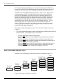
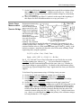
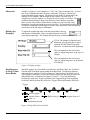
The instruNet Data Tree
instruNet stores field settings in a hierarchical data tree illustrated in figure 2.4.
Network #
{0...32}
Device #
{0...32}
Module #
{1...32}
Channel
# {1...}
Setting Group
# {-32K...32K}
Field
Figure 2.4 Network Hierarchy for instruNet
2-8
instruNet User's Manual
Ch 2 instruNet Tutorial
To access a piece of information, you must supply an address within this data tree.
This address consists of 6 parameters, as described below:
Network Number
If 0, this refers to the Driver itself (e.g. plot lines or dots in the
Record displays); otherwise, this number refers to an instruNet
Controller board, where the first board found in the computer is
designated Network Number 1, the 2nd board found is
Network #2, etc.
Device Number
This refers to hardware devices (e.g. Model 100) attached to an
instruNet Controller board, where the hardware Device closest
to the Controller is Device #1, the next device is Device #2, etc.
Module Number
This refers to the module within a hardware device. At this
time, all Devices have only 1 module that is referred to as
Module #1.
Channel Number
This refers to a specific channel in a hardware device. Each
channel typically corresponds to a physical wire somewhere,
such as a voltage input, voltage output, digital input, or digital
output. For example, in the Model 100, the screw terminal
marked "Ch1 Vin+" is Channel #1 and is a voltage input.
Setting Number
Each channel includes different Settings areas such as: lowpass
filter settings, highpass filters settings, Hardware settings, etc.
It is here that one selects a settings group (e.g. Lowpass Filter
fields have a Settings Number of -9).
Field Number
This is the Field Number {1..8} within a settings group. For
example, in the Lowpass Filter settings group, the cut-off
frequency in Hertz is stored in Field #5.
The instruNet World user navigates within this data tree via the Probe dialog,
described in the next discussion. instruNet World does not require the user to know
about Setting numbers and Field numbers since all items are defined using popups
and edit fields. The programmer, on the other hand, must supply 6 numbers to a
subroutine to read and write to any field on the instruNet data tree.
The Network page shows the current Field settings for each channel in a tabular (i.e.
spreadsheet) format, and is also a useful tool for navigating around the instruNet data
tree. The data tree maintains any changes you make until you Reset the network via
the Reset button, reset the computer, or load in new setting from disk via the Restore
or Open buttons at the top of the Network page. In many cases, a user will set the
fields as needed, stored them to disk, and then reload them when instruNet world is
first opened.
instruNet User's Manual
2-9
Ch 2 instruNet Tutorial
Explore Your World
• Run instruNet World if it is not already open.
• Select the Network page by pressing the Network tab at the bottom of the
window.
• Press the Reset button at the top of the window to reset all Fields in the Data Tree.
Press OK when a dialog asks for confirmation.
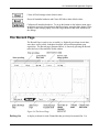
Figure 2.5 illustrates how information is organized in the Network page. The
channels that are displayed on your computer will vary depending on what hardware
is installed; therefore, don't worry if your screen is a little different from the Figures.
Figure 2.5 Partial view of the Network Page
The Network
Page
Each row in the Network page corresponds to an input or output channel,
which is often associated with a physical sensor in the real world. Each
channel has a {Network, Module, Device, Channel} address both
within the software data tree and the physical outside world. This address is
shown in the first 4 columns of the Network page. The first column indicates the
Channel name and number. For example, "Ch1 Vin1+" is Channel #1 and the
channel name is "Ch1 Vin1+". Columns #2 through #4 indicate the channel's
Network #, Device # and Module #, which correspond to a physical address.
The column labeled "Value Input" depicts the current real-time value (input or
output) of the channel, in engineering units. All columns to the right of the Value
Input column are Fields that specify the type of signal connected to the channel
and how it is being read. The horizontal and vertical scroll bars are used to move
around and make changes to the tables contents. To change a Field's setting, one
can click on its cell and then change its value. For example, to change the name
of channel Ch1 Vin1+, one would click on the "Ch1 Vin1+" cell.
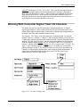
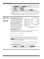
• Click on any cell in the Units Label column to open the Probe dialog, as shown in
figure 2.6.
2 - 10
instruNet User's Manual
Ch 2 instruNet Tutorial
Settings popup
Network #
Device #
Module #
Channel #
Fields for General settings area
Figure 2.6 The Probe Dialog
The Probe
Dialog
Using the Probe dialog, any Field within the instruNet Data Tree can be viewed or
modified. The upper-most 4 popup menus specify a channel address (i.e.
Network, Device, Module, Channel), the Settings popup specifies a Setting
group (e.g. General, Lowpass Filter, Highpass Filter, etc), and the Settings area
shows between 1 to 8 Fields depending on the Settings group selected.
For example, in Figure 2.6, we are viewing the General settings for channel Ch1
Vin+, which is physically connected to the 1st Device (a Model 100) attached to the
1st Controller (i.e. Network), which is plugged into computer slot #12. The General
settings group contains 4 Fields: Value Input, Units Label, User Name, and %
Sample Rate.
The Value Input field shows the real-time, current value, of the channel, Units Label
is the displayed label for the channel's value (e.g. "Volts", "Amps", "C"), User
Name is the user's name for the channel (e.g. "Temp 1", "Pressure 2", etc), and %
Sample Rate is the speed, as a fraction of the Master Sample Rate, that the channel is
digitized (e.g. 50% would mean the channel is digitized at one-half the sample rate
specified in the master Setup dialog). The small display at the bottom of the Probe
dialog shows a plot of the current real-time value of the Channel.
• Click on the Units Label field and change "Volts" to "Amps". Click OK to exit the
Probe dialog.
The clicked on cell should be update to "Amps", as shown in figure 2.7.
instruNet User's Manual
2 - 11
Ch 2 instruNet Tutorial
Figure 2.7 Edited cell within the Network page
• Scroll through the Fields of the Network page using the horizontal scroll bar at the
base of the window.
Notice that the first 5 columns remain fixed, while the cells to the right of Column #5
shift left and right with the horizontal scrollbar. You can scroll through, and view,
all Fields for all Channels in this manner. Figure 2.8 shows the Network Page for
Ch1 Vin+ after scrolling a little to the right.
Figure 2.8 Network Page scrolled horizontally to view the Ro & Rshunt Fields
• Scroll horizontally to the left edge so that "Value Input" is in Column #6 and then
scroll vertically until an input channels is no longer in the top row. For example,
in Figure 2.9, a Voltage Output channel is in the top row.
Notice that the title to Column #6 changed from Value Input to Value Output. This is
because the titles are optimized for the one channel in the top row.
Figure 2.9 Network Page scrolled vertically to view the title for voltage outputs.
• Vertically scroll to the top of the table and then click on the net cell of the first row.
(it should contain a 1) This will cause the Probe dialog to open and to display the
clicked on cell.
Channel
Addresses
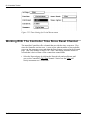
The upper region of the Probe Dialog, shown in Figure 2.10, is used to select a
Channel's address (i.e. Network Number, Device Number, Module Number, and
Channel Number).
Figure 2.10 Network Address Configuration section of Probe Dialog
2 - 12
instruNet User's Manual
Ch 2 instruNet Tutorial
When instruNet World resets (e.g. powers on), the expansion slots in the computer
are scanned for instruNet controllers. Each controller found is given a Network
Number. For example, in Figure 2.10, instruNet World found a controller in Slot
14 of a computer and designated the network connected to it as Network #1. Hence
the popup reads #1 Slot 14. This popup enables the user to select any instruNet
controller installed on the computer. There is a special "Controller" in the popup
that is labeled "Driver" (Network #0). This refers to the instruNet Driver itself, and
appears only once in the Network popup no matter how many Controllers appear.
The Driver contains fields that determine things like the way displays show data in
the Record page.
The Device popup menu lists the network Devices that are attached to the Controller
specified in the Network popup menu. When you select a Controller in the
Network popup, all devices attached to it appear in the Device popup. In the figure
shown to the left, only one network device is attached to the Controller in Slot 14
and it appears as the second item in the popup. It is a Model 100 and is designated
Device #1 (1 #100). The Controller itself is a Device (Device #0) and appears as the
first item in the Device popup. The Controller contains Fields that are specific to the
controller, such as the network sample rate, or the value of a digital output on the
Controller's Digital I/O Connector.
The Module popup lists all Modules in the currently selected {Network, Device}.
Most Devices only have 1 module, as shown to the left.
The Channel popup lists all analog and digital I/O channels in the currently selected
{Network, Device, Module}. The illustration to the left shows 3 channels, 2 of
which are voltage inputs, and the 3rd which is a voltage output.
• Explore your instruNet world via the 4 Channel Address popup menus at the top
of the Probe dialog, and the Settings popup menu. Press OK when you are done
exploring.
Saving &
Loading
Network
Settings
All instruNet Fields (i.e. all the cells in the Network page) are saved to disk and
loaded from disk with the press of a button. When a configuration is saved, all
information including items such as trigger conditions, sample rates and channel
units are stored. Waveform data is not stored at this time, but can be saved by
pressing the Save button in the Record page. When a configuration is loaded, all
items are restored to their previously saved condition. This means that instruNet
configurations for specific experiments only need to be set up once. And once a
configuration is loaded, it can be changed and then saved again if needed, possibly
in a different file.
• Select the Network page by clicking the Network tab.
The first two buttons at the top of the Network Page, Restore and Store, work as a
pair. Clicking the Store button saves the current network settings to a preferences
file within your operating system folder. Clicking Restore loads in this file. File
open and save dialogs do not appear, since the Fields are always saved to the same
file (i.e. a file with the same name). Obviously, you loose your last saved network
when you press the Restore button (careful !).
• Press the Store button to save your current Field settings to disk.
instruNet User's Manual
2 - 13
Ch 2 instruNet Tutorial
• Press the Clear button to erase your Field settings to their default values.
Notice how the "Amps" units label has now returned to its default setting of "Volts".
• Press the Restore button to restore the previously saved settings.
Notice how the "Amps" units label has returned. To save the settings to the file of
your choosing, click the Save and Open buttons.
• Press the Save button . Type a file name and select a file location when the File
Save dialog appears. Remember where you put this file.
• Now press the Clear button to clear all settings to their default values.
• Press the Open button and select your saved file in the File Open dialog.
Notice how the "Amps" units label now appears. At this time, you have 2 files on
your hard disk with your saved network settings.
The Reset button differs from the Clear button in that it resets the hardware in
addition to clearing your fields. It has the same affect on an instruNet network as
restarting the computer. For example, Reset will reset clock in the controller,
whereas Clear will not.
Working with Sensors
Any voltage input channel can attach to any of the following sensors: Voltage source,
Current source, Resistance source, Strain Gage, RTD, or types J, K, T, E, R, S, B,
and N Thermocouples. Sensors can be wired in a variety of configurations
including: Differential Voltage Measurement (requires 2 voltage input channels, e.g.
Ch1 Vin+ and Chi Vin-), Single-ended Voltage Measurement, Shunt Resistor,
Voltage Divider, Bridge, Quarter Bridge and for strain gages: Half-Bridge Bend,
Half-Bridge Axial, Full-Bridge Bend, Full-Bridge Axial I and Full-Bridge Axial II.
• Select the Network page by clicking on the Network tab.
• Click on the name of the voltage input channel with the attached signal source
(e.g. "Ch1 Vin+").
The Probe dialog will open with the address of the channel you clicked on
displayed in the Network Address. Additionally, the real-time value of the
channel, in Engineering Units (EU) will appear at the bottom of the display, as
shown in Figure 2.11.
Real-time plot of channel’s value
Actual reading in Engineering Units
2 - 14
instruNet User's Manual
Ch 2 instruNet Tutorial
Figure 2.11 The Snapshot Display
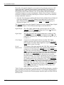
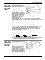
• Select Hardware in the Settings popup, as shown in Figure 2.12.
Figure 2.12 Hardware Settings Area
• Click on the Sensor popup to view the various Sensors that
can directly be attached to this channel, as shown to the right.
This popup tells instruNet which sensor is connected to your
physical hardware terminals (instruNet has no way of seeing
what is out there). For more detailed information on
connecting sensors to instruNet, please refer to Chapter 3
Connecting to Sensors.
• Click on the Wiring popup and view the choices, as illustrated to the left.
The Vin+ - Vin- option is used for differential Voltage measurements to measure the
voltage between the Vin+ and Vin- terminals. The "common" signal on both
terminals is ignored, and therefore this technique can be used to reduce noise. The
Vin+ - Gnd option specifies Singled-Ended voltage measurement, which measures
the voltage between the voltage input terminal and the Ground terminal. The latter 6
options (Q Bridge, Half Bridge Bend, Half Bridge Axial, Full Bridge Bend, Full
Bridge Axial I and Full Bridge Axial II are used to specify a wiring options when
working with a Strain Gage sensor. These wiring options are described in more
detail in Chapter 3.
• Click on the Range popup and view the options, as illustrated to the left. Select
the largest range (e.g. +- 5V).
This Field specifies the voltage input range. Accuracy is increased as the range is
reduced. For example, a +-80mV range might be accurate to +-100uV, whereas a
+-5V range might only be accurate to +-2mV. If you input a voltage in excess of a
bound, the bound is read. For example. If you apply 3V a voltage input with a +1.25V range, then +-1.25 will be read by the computer.
instruNet User's Manual
2 - 15
Ch 2 instruNet Tutorial
• Click in the Low Pass popup and view the options, as illustrated to the left.
The options that you see will depend on the connected hardware device. This Field
is used to select an analog filter at the front end of the voltage input amplifier.
Please consult Chapter 6, Hardware Reference to learn more about the analog filter
options for each hardware Device.
The Integrate field specifies how long, in Seconds, instruNet averages an input
signal before 1 number is returned to the user. This is often used to reduce high
frequency noise that has been added to a signal. The integration feature is
implemented by sampling the signal many times with the A/D converter, as fast as it
can, and then averaging the A/D values with software. The maximum allowable
integration time depends on the number of digitized channels and the sample rate.
For example, 2 channels could be sampled at 1000s/sec per channel and integrated
each for .5ms.
• Select Constants in the Settings popup, as illustrated in Figure 2.13.
Figure 2.13 Constants Settings Area
These Fields are used to specify constants that are used to calculate engineering units
when working with Resistance, Current, RTD, and Strain Gage sensors. For
example, Rshunt specifies the value of the shunt resistor, in ohms, when doing a
Resistance measurement. Please refer to Chapter 3 for details on how to use these.
• Click OK in the Probe Dialog to return to the Network page.
• Enable the first three voltage input channels for digitizing by clicking once on
Column #5 of each channel, as illustrated in Figure 2.14.
Figure 2.14 First 3 channels of Model 100 are enabled for digitizing.
• Select the Record page by clicking on the Record tab at the bottom of the window.
2 - 16
instruNet User's Manual
Ch 2 instruNet Tutorial
• Click the Start button to begin recording.
The Record Page automatically creates a separate display for each recorded channel,
as shown in Figure 2.15. The actual signal that appears will depend on the
connected signal sources.
• Click the Stop button to Stop recording.
Channel Name Box
Figure 2.15 Three Channels in Record Page
Each display has a Channel Name box which appears to the right of the display, as
shown to the left and in figure 2.15. This box displays the channel name and the
real-time channel value in Engineering Units.
• Click on the Channel Name box of the top-most display to open the Probe dialog
at the Display settings area, as show in Figure 2.16.
Figure 2.16 Display Settings
• Change the Disp Max EU Field to 2, change the Disp Min EU Field to -2, and
click the lower-right Enter button.
These 2 Fields are used to set the top and bottom plot values of the vertical axis in
both the Record page display and the Probe dialog snapshot display. These changes
take affect when the Enter button is pressed, and can be viewed at the bottom of the
instruNet User's Manual
2 - 17
Ch 2 instruNet Tutorial
Probe Dialog, as shown in Figure 2.17. In many cases, one must edit these values,
depending on the Engineering Unit range of the digitized signal. For example, one
might set 0 and 100 for a temperature that ranges from 0 to 100C.
New top and bottom vertical axis bounds
Figure 2.17 Probe display with E.U.'s set to +/- 2V
• Press OK to exit the Probe dialog, and then press Start to begin recording.
Notice how the vertical axis scale change effects the appearance of the recorded
signal, as shown in Figure 2.18.
Figure 2.18 Record Page with top display Min/Max E.U. set to +/- 2V
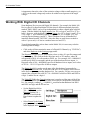
Working with instruNet BASIC
instruNet BASIC enables users to automate the setting up of channels, digitizing,
viewing results, and saving to disk. It is predicated on the BASIC programming
language, and features many additional commands that facilitate working with
instruNet hardware. instruNet BASIC builds on the instruNet World strip chart
recorder by automating common tasks done at experiment time. This is
especially helpful at reducing the chance of error, and making the data taking
process more pleasant. A person who is not too familiar with the computer,
doing many manual steps, at a fast pace, under pressure, can lead to a problem.
instruNet BASIC addresses that issue by consolidating a series of steps into one
button press in the instruNet World window. For details concerning this
powerful language, please see Chapter 9, instruNet BASIC.
2 - 18
instruNet User's Manual
Ch 2 instruNet Tutorial
Simple
Example
• Press the BASIC tab at the base of the window, to select the BASIC page,
which is used to develop and execute instruNet BASIC code.
The BASIC text editor is used to create, edit, view, execute, and test instruNet
BASIC files, which are based on standard text files, and appear as regular
unformatted text.
• Please type the following into the window:
Delete Buttons
NewButton BASIC "Print 3x"
For c! = 1 to 3
Print (channel(1/1/1/1))
Next
EndButton
End
"\r"
• Press the Execute button to execute the code. A button should appear at the
top of the window entitled, "Print 3x".
• Press this button, and notice how the value of channel 1/1/1/1 (i.e. Channel
#1, from Network #1, Device #1 and Module #1) is printed three times.
• Press the Save button to save your code to disk in a text file.
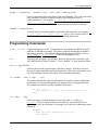
The first line of your program, "Delete Buttons", causes all previously created
buttons to be deleted, so they do not accumulate each time you run this program.
The NewButton command creates a new button in the BASIC page with the name
"Print 3x". The code between NewButton and EndButton executes when "Print
3x" is pressed. This button causes a loop to execute 3 times, via the For
statement. The body of the For loop is a simple print statement that prints the
value of channel 1/1/1/1 and a carriage return character.
Congratulations! You have now completed your first program.
Benefits
What can instruNet BASIC do for ME ?
instruNet BASIC can create more text editor pages within instruNet World for
data and notes, each with their own tab at the base of the window. And BASIC
can easily print notes and data to these pages, save the text to disk, and load text
from disk. Also, with several lines of BASIC code, one can spool digitized data
to disk in one large text file, filling a 2 GByte file at rates of approximately 5000
points/second. instruNet BASIC can also create buttons at the top of the
instruNet World window that execute BASIC code when pressed. Buttons can
be used to set up the calibration of channels, record data, save data, and view
data. instruNet BASIC can declare a list of channels, that are many channels
long, and then with one line of code, globally set a field (e.g. sensor type,
wiring, integration) for each of those channels. This enables one to set up
channels without manually setting fields within the instruNet Network page. For
more details, please see the text files in folders "instruNet\ BASIC\ Examples\ ",
and "instruNet\ BASIC\ Documentation\". One can read these by pressing the
BASIC tab at the base of the instruNet World window, pressing the Open button,
and then navigating to the instruNet\ BASIC\ directory.
instruNet User's Manual
2 - 19
Ch 2 instruNet Tutorial
DVM Example
• Press the Open button, navigate to file "instruNet\ BASIC\ Examples\
DVM.iBs", and load the file into the instruNet BASIC text editor.
• Press the Execute button to run this program, and press the Stop button when
done monitoring its activity.
This program reads several channels and prints them to one line in the text editor,
once each second, simulating a digital voltmeter.
Math Example
• Press the Open button, navigate to file "instruNet\ BASIC\ Examples\
MathExp.iBs", and load the file into the instruNet BASIC text editor.
• Press the Execute button to run this program.
• Scroll up and down to review the various math-oriented features.
MathExp.iBs demonstrates many mathematical functions, bitwise operators,
logical expressions, string functions, and time related features.
Print Example
• Press the Open button, navigate to file "instruNet\ BASIC\ Examples\
Print.iBs", and load the file into the instruNet BASIC text editor.
• Press the Execute button to run this program.
• Scroll up and down to review the various print and string related features.
Data
Acquisition
Example
• Press the Open button, navigate to file "instruNet\ BASIC\ Examples\
TakeData.iBs", and load the file into the instruNet BASIC text editor.
• Press the Execute button to run this powerful program.
This code creates a new page called "Data", creates several buttons for this new
page, and selects the new page.
• Press the BASIC tab at the base of the window to return to the original code,
and then press the Data tab to return to the new data taking page.
• Press the Setup button to set up several channels, per the TataData.iBs Setup
button code.
• Now press the Record button to digitize data into the Data page. Hold the
mouse down to stop the data taking after several lines have been printed.
This program shows how instruNet BASIC can set up channels, record into a
text editor, and spool a large 2Gbyte file to disk (via the Spool button).
To Learn More
2 - 20
The "instruNet\ BASIC\ Examples\ ..." directory contains many simple example
programs. To learn more about instruNet BASIC, please load and run several of
these examples, and also see Chapter 9, instruNet BASIC.
instruNet User's Manual
Ch 2 instruNet Tutorial
Working With Calibration, Different Scales, & Mapping
instruNet supports Calibration and Converting to different scales (e.g. show psi
at sensor instead of Volts at screw terminals) with a 2 point mapping scheme. All
channels have a Mapping settings area that defines the relationship between
"internal units" and "external units". Internal units are the native units used by
instruNet, such as Volts. External units are what the user sees in the Record
page, the Network page, and the numbers returned by iNet(). External units are
linearly mapped to Internal units, and are therefore defined with 4 numbers, that
define 1 line ({x1,y 1}, {x2,y 2}), on an Internal Units Vs. External Units 2dimensional coordinate axis plane.
Sounds a little complicate? Imagine a linear temperature sensor that puts out
.1Volts when dipped in ice water (0°C) and 1Volts when dipped in boiling water
(100°C); and you want instruNet to display °C numbers in the Record page and
the Network page. To do this, one would set the Mapping fields to:
internal1 : .1 (Volts)
external1 : 0 (°C)
internal2 : 1.0 (Volts)
external2 : 100 (°C)
And set the Units Label field in the General Settings area to "C". The Units
Label does not effect instruNet numerically, yet is interpreted as random text that
is simply placed next numbers (i.e. it is a "label"). The Mapping fields;
however, effect numbers, yet not labels.
The Mapping numbers can also be used to implement calibration. Suppose a
thermocouple (i.e. temperature sensor) is attached to instruNet and is already
returning °C numbers (since that is the native units for the thermocouple), yet you
find there is a 2°C offset error in your sensor, and want instruNet to "correct" for
this error. To do this, the user would set up a mapping from internal units to
external units that reflected the offset error. e.g.
internal1 : 100 (°C)
external1 : 102 (°C)
internal2 : 0.0 (°C)
external2 : 2.0 (°C)
Notice that Mapping can be used to correct for an offset error by adding a
constant and can correct for a gain error by multiplying by a constant.
The Mapping setting area describes a line using two different methods: two
points "{x1,y 1}, {x2,y 2}", and "y = x*scale + offset". One can use either
method. For example, instead of setting the above 4 values, one could have set
the Offset field to 2.0, to show a 2°C Offset. When the Scale or Offset fields are
changed, the x1,y 1,x 2,y 2 fields update automatically to reflect the new line when
the OK or Enter button is pressed.
instruNet User's Manual
2 - 21
Ch 2 instruNet Tutorial
Working with Digital Filters
All voltage input channels support digital lowpass, highpass, bandpass and bandstop
filters. The cut-off frequencies, minimum dB stopband attenuation (i.e. filter order),
maximum dB passband attenuation, and filter type (e.g. elliptic, Chebyshev B,
Chebyshev S, and Butterworth) can all be programmed separately for each channel
via the Lowpass, Highpass, Bandpass and Bandstop Settings areas. In fact, these 4
models can be run at the same time (i.e. in serial) to simultaneously do lowpass,
bandpass, bandstop and highpass filtering on the same channel. For example, one
might only want to see frequencies between 20 and 1000Hz, except for the 55 to 65
band. This would involve a highpass filter at 20Hz, a bandstop filter between 55 and
65Hz, and a lowpass filter at 1000Hz.
• Select the Network page by clicking on the Network tab and then press the Reset
button to reset the network and all Fields.
• Click the channel name cell of the channel that is attached to your signal source
(e.g. Ch1 Vin+), and then select Lowpass in the Settings popup, as shown in
Figure 2.19.
Figure 2.19 Lowpass Filter settings area
The lowpass filter is illustrated in Figure 2.20. Notice that 4 numbers are needed
to describe the lowpass filter: minimum stop band attenuation (dB), maximum
pass band ripple (dB), pass band cut-off frequency (Hz) and stop band cut-off
frequency (Hz). And notice how these 4 numbers corresponds to the StopB
Attn, PassB Ripple, PassB F1 Hz, and StopB F1 Hz Fields in the Lowpass
Filter settings area.
• Turn the filter On by selecting Elliptic in the Filter popup (or any of the other
options other than Off).
• Enter a passband cut-off frequency value into the PassB F1 Hz field, a
stopband cut-off frequency into the StopB F1 Hz field, a minimum stop band
attenuation into the StopB Attn field, and a maximum pass band ripple into the
PassB Ripple field. Acceptable values would be {100, 150, 80, 1}. Press the
Enter key when done setting the values. If the filter is impossible to design
due to constraints of the specified values, an alert will appear with a message
coaching the user into selecting different parameters. In fact, instruNet will not
allow you to exit this dialog until the parameters are acceptable, or the filter has
been turned off by selecting Off in the Filter popup.
2 - 22
instruNet User's Manual
Maximum Pass
Band ripple (dB)
(PassB Ripple)
Passband
Minimum Stop Band
attenuation (dB)
(StopB Attn)
Transition
Amplitude
Ch 2 instruNet Tutorial
PassB F1 (Hz)
Stopband
StopB F1 (Hz)
Frequency
Figure 2.20 Lowpass Filter Model
The filter order ranges from 1 to 32 in bandpass and bandstop filters, and from 1
to 16 in highpass and lowpass filters, depending on the supplied parameters. As
the filter becomes more demanding, the filter order increases, and the time to run
the filter also increases. In a typical case, it takes .1 to 2us per order per point to
run the filter. For example, on a Macintosh 840av (1993 technology) it takes 2us
per order per pt or 20us per point to implement a 10th order filter. This would
limit the maximum sample rate to 50Ksamples/second (i.e. 1 / 20e-6 = 50e3).
• View the results of your filter by observing the effect it has on the waveform in the
Snapshot display. If you have a function generator connected, watch what
happens when you slowly change its frequency from 10Hz to 500Hz, for
example.
Figure 2.21 shows a 35 Hz signal applied to Ch1 Vin+, before and after the
implementation of a 30 Hz lowpass filter.
Figure 2.21 35 Hz Sine Wave before and after 30 Hz Lowpass Filter
Figures 2.19 through 2.21 show the filter models for the Highpass, Bandpass
and Bandstop filters.
instruNet User's Manual
2 - 23
Maximum Pass
Band ripple (dB)
(PassB Ripple)
Minimum Stop Band
attenuation (dB)
(StopB Attn)
Transition
Amplitude
Ch 2 instruNet Tutorial
Stopband
StopB F1 (Hz)
Passband
PassB F1 (Hz)
Frequency
Passband
Transition
Amplitude (DB)
Stopband
Transition
Figure 2.22 Highpass Filter Model
Stopband
Maximum Pass
Band ripple
(PassB Ripple)
Minimum Stop
Band attenuation
(StopB Attn)
StopB F1
PassB F2
PassB F1
StopB F2
Frequency (Hz)
Amplitude (DB)
Stopband
Transition
Passband
Transition
Figure 2.23 Bandpass Filter Model
Passband
Maximum Pass
Band ripple
(PassB Ripple)
Minimum Stop
Band attenuation
(StopB Attn)
PassB F1
StopB F2
StopB F1
PassB F2
Frequency (Hz)
Figure 2.24 Bandstop Filter Model
2 - 24
instruNet User's Manual
Ch 2 instruNet Tutorial
Table 2.1 shows which fields in the Settings area must be set for each filter model.
Edit field or
popup
Filter popup
PassB Ripple
StopB Attn.
PassB F1 Hz:
StopB F1 Hz:
StopB F2 Hz:
PassB F2 Hz:
Lowpass
Highpass
Bandpass
Bandstop
used
used
used
used
used
not used
not used
used
used
used
used
used
not used
not used
used
used
used
used
used
used
used
used
used
used
used
used
used
used
Table 2.1 Fields required for each Filter model
• Play with the different filter models and settings while viewing their effects in the
snapshot display. For example, to turn on a highpass filter, select Highpass Filter
in the Settings popup, select Elliptic in the Filter popup, and then set the PassB F1
Hz, StopB F1 Hz, StopB Attn, and PassB Ripple fields as desires using Figure
2.19 as a guide. Remember to press the Enter button to create the filter.
Working With Voltage Output Channels
Some hardware devices, such as the Model 100, provide Voltage Output channels.
In summary, these channels output the Voltage specified in the Value Output field
within the General settings area. Accuracy's are discussed in Ch6, Hardware
Reference. Voltage Output channels are named ChX Vout in the Network Page.
• In the Network page, click
on the 1st cell of the first
voltage output channel. For
the Model 100, this would
be the "Ch3 Vout" channel.
When the Probe dialog
opens, set the Value Output
field to 1, and press the
Enter button, as illustrated to
the right.
The analog output channel is
immediately updated to the new
value when Enter is clicked.
• Click OK to return to the Network page and view the Value Input column for the
chosen Voltage output channel. It should display a value in the vicinity of 1V.
With Voltage outputs, instruNet reads back the output voltage and displays this value
in the Value Out column. This is useful information when loading of the output
signal will change its value. An example of this is a bridge excitation circuit where it
instruNet User's Manual
2 - 25
Ch 2 instruNet Tutorial
is important to know the value of the excitation voltage within a small margin (e.g. to
±.01%) yet the actual voltage only needs to be within several percent of the target
voltage.
Working With Digital I/O Channels
Some hardware Devices provide Digital I/O channels. For example, the Model 100
Device offers 8 bi-directional digital I/O bits where 8 different terminals physically
marked "DIO1..DIO8" can be set up independently as either a digital input or digital
output. With the Model 100 digital outputs, 0 to .8V is a logic 0, and 2V to 5V is a
logic 1; however, with the Model 100 digital inputs, 0 to 1V is a logic 0, and 3.2V to
5V is a logic 1. Also with these signals, voltages above 12V or below -12V will
result in physical damage (careful !). These 8 hardware bits are all handled by 1
instruNet channel named "Ch25 Dio", where the 8bits are read from or written to
with a 1 byte word (i.e. 8 bits in a number between 0 and 255).
To set digital output bits, such as those on the Model 100, it is necessary to do the
following kinds of things:
• Click on the cell that contains the name of a Digital I/O Channel (e.g. "Ch25 Dio")
and select Hardware in the Settings popup menu.
The Direction field specifies the bit direction, where a value of 1 specifies output, and
0 specifies input. This field packs the 8bits into one 0 to 255 number, where d0
corresponds to DIO1, d1 corresponds to DIO2, etc. For example, 410 = 000001002
would specify DIO3 as an output, and the rest of the hardware bits are inputs. A
Direction value of 010 = 000000002 specifies all hardware bits as inputs, and a value
of 25510 = 111111112 specifies all bits as outputs.
The Digital Out field is used to set the state of the bits that have been marked as
outputs by the Direction field. It does this with one 0 to 255 number where each bit
in the byte sets its corresponding hardware bit. For example, if 8 bits were set up as
outputs, then a Digital Out value of 1710 = 000100012 would set DIO1 and DIO5 to
a logic 1, and the rest to a logic 0.
The Value EU field in the General settings area is used to read the states of the 8 bits
via a 0 to 255 number where each bit in the received byte corresponds to a hardware
bit. For example, reading 310 = 000000112 would mean that hardware bits DIO1
and DIO2 are high, and the rest are low.
• Set the Digital Out field to
310 = 000000112, set the
Direction field to 110 =
000000012 and click the
Enter button to update the
bits.
• Select General in the Setting
popup menu and note the
value displayed in the Value EU field.
2 - 26
instruNet User's Manual
Ch 2 instruNet Tutorial
Value EU should show 253 10 = 111111012. This is because the high 6 bits have
been set up as digital inputs in the Direction field, and if nothing is connected to
them, they will float high to a logic 1. DIO1 is set up as an output in the Direction
field, and has been set to a 1 in the Digital Out field, and is therefore read as a 1.
DIO2 has also been set up as an output in the Direction field, yet has been set to a 0
in the Digital Out field, and is therefore read as a 0.
Working With Controller Digital Timer I/O Channels
The Model 200 and 220 (not 230) instruNet Controller boards have 10 digital
input/output channels, each of which can be used for period measurement, clock
output, digital input or digital output. Each of these channels runs independently of
the others, and of the other channels on the network.
For example, "Ch1 Timer" is the first channel in a controller board. Its network
address is Device 0, Module 1, Channel 1; and its physical location is two pins on a
34 pin header connector located on the controller board. The two connector pins are
labeled "Ch1 Din" and "Ch1 Dout", one for digital input and one for digital output.
With the controller digital outputs, 0 to .8V is a logic 0, and 2V to 5V is a logic 1;
however, with the controller digital inputs, 0 to .8V is a logic 0, and 3.5V to 5V is a
logic 1. Also with these signals, voltages above 6V or below -6V will result in
physical damage (careful !). An instruNet Field is used to specify the function of
Channel 1 as digital input, digital output, clock output or period measurement. If
digital input or period measurement are chosen, the "Ch1 Din" pin is used;
otherwise, the "Ch1 Dout" pin is used.
Figure 2.25 The Timer Settings Area
instruNet User's Manual
2 - 27
Ch 2 instruNet Tutorial
Physically, all controller channels are accessed at a 34 pin header connector (.025"
square pins with .1" spacing) located on the Controller board. This connector is
independent of the DB25 Connector that is used to cable to the network Devices.
One typically cables to this connector via a 34-wire ribbon cable that terminates
outside the computer at a screw terminal panel. Please refer to Chapter 1 Hardware
Installation for details on cabling, and Chapter 6 Hardware Reference for details on
each pin within this connector.
• Select the Network page by clicking the Network tab, and then click in Column #1
of the first controller's Ch 1 Timer channel (you might need to scroll down a
little). When the Probe dialog appears, select Timer in the Settings popup, as
illustrated in Figure 2.25.
The Function popup selects the channel's Function to be one of Digital Input, Digital
Output, Clock Output or Period Measurement Input, as described below:
Digital Output
The "ChX Dout" connector pin is set to a logic 0 (0-.8V) if the
Value I/O field in the General settings area is set to a 0; otherwise,
this pin is set to a logic 1 (2V-5V).
Digital Input
The Value I/O field in the General settings area is read as 0 if the
"ChX Din" connector pin is held by an external source below .8V
(otherwise, it floats to 5V). However, if this pin is above 3.5V, it
is read as a 1.
Clock Output
A square wave clock signal is driven out of the "ChX Dout"
connector pin where the cycle time is specified by the Clk Period
field, in units of seconds, and the high time is specified by the Clk
Out Hi field, in units of seconds.
Period
Measurement
The duration of the signal applied to the "ChX Din" connector pin
is measured and returned in the Value I/O field of the General
settings area, in Seconds units. If the Measure field is set to Cycle
time, the time is measured between consecutive falling edges;
otherwise the time is measured between a rising edge and the next
falling edge. The Meas Cycles field varies from 1 to 255 and sets
the number of cycles (or high times) that must occur over the
measured duration. For example, measuring 10 cycles of a 1KHz
square wave would return 10ms; whereas measuring 5 high times
of a 20KHz square wave would return 125us. If the Meas Resol
popup is set to .25us, the measurement is accurate to .25us and the
falling-edge-to-falling-edge time (or rising-edge-to-falling-edge)
must range from 3us to 16ms. Otherwise, if the Meas Resol popup
is set to 4ms, the measurement is accurate to 4ms and the fallingedge-to-falling-edge time (or rising-edge-to-falling-edge) must
range from 12ms to 576 secs.
Table 2.2 shows which Fields are used for each of the different functions. instruNet
ignores settings not needed for a particular function. For example if Digital Input or
Digital Output is selected in the Function popup, instruNet ignores all other Fields in
the Timer area.
2 - 28
instruNet User's Manual
Ch 2 instruNet Tutorial
Field
Clk Period
Clk Out High
Measure
Meas. Resol.
Meas. Cycles
Digital In
not used
not used
not used
not used
not used
Digital Out
not used
not used
not used
not used
not used
Clock Out
used
used
not used
not used
not used
Period Meas.
not used
not used
used
used
used
Table 2.2 Fields used with different Controller Digital I/O Functions.
We will now set up one channel as a clock output and measure its duration with
another channel. This will require a 34 wire screw-terminal block cabled to the
digital connector on a Model 200 or 220 instruNet Controller board. If you do not
have a screw terminal block wired to your Controller, you can still do this
experiment, yet the measured period will not be correct.
• Connect a physical wire between Pin #6 (Ch1 Dout) and Pin #7 (Ch2 Din) of the
Controller Digital I/O connector.
• Set the Function popup to
Clock Out, the Clk Period
field to .005, and the Clk Out
Hi field to .001.
• Select General in the Settings
popup and set the User Name
field to "Clock Out".
• Click the Enter button in the
bottom right of the Probe
Dialog to start the clock
output.
• Select Ch2 Timer in the
upper-right Channel popup to select the 2nd channel in you instruNet Controller.
• Set the User Name field to "Clock Meas".
• Select Timer in the Settings popup.
• Set the Function popup to Period Meas, set the Resolution popup to .25µs, set the
Measure popup to Cycle Time, and set the Meas Cycles field to 1; as shown in
figure 2.25.
• Press OK to return to the Network page.
Notice how the names of your
first two Controller channels have
changed to "Clock Out" and
"Clock Meas", and how Clock Meas's Value field is displaying .005 seconds of
measured period. This is the period of the clock signal being output by Ch1 Timer
and being measured by Ch2 Timer. If you remove the wire connecting the Output of
Ch1 Timer and the input of Ch2 Timer, the Value field will change.
instruNet User's Manual
2 - 29
Ch 2 instruNet Tutorial
Figure 2.25 Timer Settings for Period Measurement
Working With The Controller Time Since Reset Channel
The instruNet Controllers offer a channel that provides the time, accurate to .25us,
since the Controller was last reset. A reset occurs when instruNet is first used after
power up, the computer resets, and when the Reset button is pressed in the Network
page. This clock channel is called "Ch12 Time" and returns a number in units of
seconds that is derived from a 62bit counter that counts 4MHz.
• Select the Network page by clicking the Network tab, and scroll down until
you see the Controller's Ch12 Time channel. Notice how the Value cell
slowly increments at a 1 second rate.
2 - 30
instruNet User's Manual
Ch 2 instruNet Tutorial
Working With Multiple Controllers
instruNet supports multiple controllers (i.e. networks) in one computer. In this case,
the meaning of the "network number" becomes more important, since it selects a
particular network in the data tree from which to operate. To digitize simultaneously
from multiple controllers, one must select channels for digitizing in the Network page
(any channel combination across all controllers), and then press the Start button in
the Record page. There is one complexity however, which is that each controller has
its own Trigger settings. This is because each controller operates independently (i.e.
each has its own processor that manages its own data acquisition task). To access a
Trigger dialog for a specific network, press the Trigger button in the Setup Dialog,
and then select a specific network in the Network popup menu.
Setting the Trigger with multiple controllers is a little tricky since one controller
cannot physically see the trigger signal attached to other controllers, and each
controller has no way of sending messages to its colleagues in a short period of time.
To make the digitizing from all networks trigger off the same signal, one must attach
the trigger signal to one channel from each network, and set up the Trigger dialogs
for each network to trigger off that one channel in each of their respective networks.
Triggering Off
A Digital Input
To trigger off the instruNet 100 Ch25 Digital Input, specify this channel as the
trigger source, attach your trigger signal to Ch25 DIO8, and set the trigger threshold
to 200. When DIO8 is high (i.e. 2-5V), Ch25 is read as {128..255}; and when
DIO8 is held low (i.e. 0-.8V) Ch25 is read as {0-127}.
Next Step
This concludes the tutorial. From here you might consider exploring the following
areas: Chapter 3, Sensor Reference, which summarizes how to connect sensors;
Chapter 4, Programmers Tutorial, which is a tutorial designed to get programmers up
and running quickly.
instruNet User's Manual
2 - 31
Ch 2 instruNet Tutorial
2 - 32
instruNet User's Manual
Ch 3 Connecting to Sensors
3 Connecting
to Sensors
This chapter describes how to connect sensors to instruNet hardware and how to
configure instruNet software for each type of sensor. instruNet allows different
sensors to be connected directly to each input channel including RTD's,
thermocouples, strain gages, resistance sources, current sources; and single-ended
and differential voltage sources. In some cases, the user must add an external
resistor to facilitate the reading of a sensor.
This chapter is not intended to be a complete reference on sensors and their use. For a
wonderful reference and catalog of temperature and strain sensors, please call USA Tel
1-800-826-6342 (Fax 1-203-359-7700) and request a free copy of "The Temperature
Handbook" & "The Pressure Strain and Force Handbook". instruNet supports a direct
connection, returning native engineering units, to the following sensors:
Sensor
Voltage
Voltage
Voltage
Current
Resistance
Resistance
Strain Gage
Strain Gage
Strain Gage
Strain Gage
Strain Gage
Strain Gage
Strain Gage
RTD
RTD
J, K, T, E, R, S, B,
& N Thermocouple
Thermistor
Units
Volts
Volts
Volts
Amps
Ohms
Ohms
Strain
Strain
Strain
Strain
Strain
Strain
Strain
Celsius
Celsius
Celsius
Wiring
single-ended
differential
bridge
shunt resistor
voltage divider
bridge
voltage divider
Q bridge
H bridge bend
H bridge axial
F bridge bend
F bridge axial I
F bridge axial II
voltage divider
bridge
differential
Celsius
voltage divider
Constants
none
none
Vinit, Vout
Rshunt
Rshunt, Vout
Ro, Rshunt, Vout
Ro,Shunt, Vout, Vinit, GF
Ro, Vout, Vinit, GF, Rlead
Ro, Vout, Vinit, GF, Rlead
Ro, Vout, Vinit, GF, Rlead, v_Poisson
Vout, Vinit, GF
Vout, Vinit, GF, v_Poisson
Vout, Vinit, GF, v_Poisson
alpha, delta, Ro, Shunt, Vout
alpha, delta, Vout, Vinit, Ro
none
Figure #
3-1
3-2
3-2b
3-3
3-4
3-5
3-6
3-7
3-8
3-9
3-10
3-11
3-12
3-13
3-14
3-15
Ro, Shunt, Vexe, Vinit, alpha, delta, GF, 3-16
v_Poisson
Table 3.1, Sensors that can directly be connected to instruNet
instruNet User's Manual
3-1
Ch 3 Connecting to Sensors
Connecting a Sensor Directly to instruNet
The instruNet voltage input terminals (often labeled "Vin(+)" or "Vin(-)") can
directly connect to a variety of sensors, with instruNet software returning values in
native engineering units (e.g. degrees Celsius, strain, Volts, Amps, ohms). This
requires wiring the sensor to the instruNet hardware in the appropriate manner, and
then configuring the instruNet software for your particular sensor, as described in
the following steps:
1) Physically Wire your Sensor to instruNet hardware
The first step is to physically wire your sensor to the instruNet hardware, per the
Hardware Reference guidelines at the end of this chapter. Each sensor listed in the
previous table is discussed in detail in this reference. For example, to connect a J
Thermocouple, one would attach the positive lead of the thermocouple to the
instruNet Vin+ terminal, and the negative lead to the Vin- terminal. The input
terminals are protected against over voltage and electrostatic discharge, therefore it is
not always necessary to power off network devices (e.g. Model 100) while wiring
sensors, although turning power off is recommended as a good safety practice. If
your sensor does not fit into one of the standard categories in the previous table, then
you need to choose the closest category, and then do the calculations necessary to
resolve your desired engineering units. If you do power OFF your network, please
use the following sequence:
1.
2.
3.
4.
5.
Power OFF powered devices connected to the Network
Power OFF Computer
Configure network cables, sensors, and devices
Power ON Computer
Power ON powered devices connected to the Network
2) Tell the instruNet software which Sensor is connected
Set the Sensor popup in the Hardware settings area of the Probe dialog to the correct
Sensor (e.g. Volts, J Thermocouple, etc). The sensors to choose from are listed in
the first column of the Sensor Hook-up Table, at the beginning of this chapter.
3-2
instruNet User's Manual
Ch 3 Connecting to Sensors
To set the Sensor popup, one would:
1. Open the instruNet World window by launching the Windows 95
"instruNet World Win32.exe" or Macintosh "instruNet World Mac"
application program (e.g. double-click on its icon).
2. Click on the Network tab at the bottom of the window to select the network
page.
3. Click on the name of your channel in the left-most column to open the Probe
dialog.
4. Select Hardware in the Settings popup menu.
5. Select the desired sensor in the Sensor popup menu, as illustrated in the
previous figure.
3) Tell the instruNet software how the Sensor is wired
Set the Wiring popup in the Hardware settings area of the Probe dialog to the correct
Wiring (e.g. Single-Ended, Differential, Bridge, Voltage Divider, etc). Please
consult the Sensor Hook-up Table, at the beginning of this chapter, for guidance.
Recall that the chosen wiring popup must match your actual physical hardware
wiring.
4) Set the appropriate constants as required
Set the fields in the Constants settings area as
needed. This involves selecting Constants in the
Setting popup, and then setting specific Constants
fields as noted in the previous table. For details on
specific sensors, please consult the Sensor Reference
at the end of this chapter. For example, to measure a
resistance instruNet needs to know the value of an
external shunt resistor "Rshunt", in ohms, and the
value of the excitation voltage "Vout", in volts, as
illustrated to the right. This would involve setting
the Rshunt and Vout Constants fields to correspond
to your actual wiring. instruNet software would then automatically return an
amplitude in "ohms" units after measuring the voltage at the Vout terminal,
measuring the voltage between the Vin+ and Vin- terminals, and calculating the
realtime Runknown.
5) Select the appropriate input voltage range
Set the Range popup in the Hardware Settings area as needed. This selects a voltage
range that is used by instruNet. If the voltage exceeds a bound, then the bound is
returned by the software. For example, if you input 2V and the range is +/- 1V then
instruNet will return 1Volt. The resolution and accuracy of the measured signal
increases when the range is reduced. For example, with the Model 100, the voltage
accuracy is 25uV in the +/-10mV range, and 1mV in the +/- 5V range with 1ms of
integration. Some sensors require a specific voltage range, or only allow one range.
For example, the range with thermocouples is always in the neighborhood of +/100mV.
6) Set the Integrate popup
Set the Integrate popup in the Hardware Settings area as needed. This selects the
duration that the signal is averaged before instruNet returns one number. For
example, if you choose 16ms, it will return the average signal value over a period of
instruNet User's Manual
3-3
Ch 3 Connecting to Sensors
16ms. This is helpful at reducing noise for signals acquired at slow sample rates
(e.g. to integrate 16ms worth of data the sample rate must be greater than 16ms per
point, or slower that 60samples/second) Each hardware device offer different
Integrate options.
7) Select the appropriate Analog Filter
Set the analog Low Pass filter popup in the Hardware Settings area as needed (e.g.
off, 40Hz, 4KHz). Each hardware device offers different analog low pass filter
options as described in Ch 8, Hardware Reference (not all devices support hardware
analog filtering). Low pass filters cause high frequencies to be rejected, while low
frequencies are passed. Visually, the signal becomes "smoother". To see the effects
of various filters, view the digitized signal at the bottom of the probe dialog, after
making different selections (you might not be able to do this until you are further
along in the set up process).
8) Set your Digital filters as needed
If you need to do a digital low pass, high pass, band pass, or band stop filter on
your digitized waveform, please set the fields in the filter Settings areas (e.g. Low
Pass, High Pass) as desired. Digital filters are run on the waveform post
acquisition, and only effect digitized waveforms (not single values read by
instruNet). Please refer to Ch2 Tutorial, Setting Digital Filters for an expanded
discussion of this powerful feature.
9) Consult the Sensor Reference for specifics
Carefully implement the Sensor Reference instructions for your particular sensor,
later in this chapter, and read the corresponding footnotes at the end of this chapter.
Different sensors require different range, filter, and constants settings; and care
should be taken to insure accurate results.
10) Check your Work
To check your work, view the incoming signal, in realtime, at the bottom of the
Probe dialog.
This display shows the sensor's value, in realtime, in native engineering units (e.g.
Volts, Amps, degrees Celsius, strain) based on your software settings and external
hardware wiring. The numerical value displayed at the bottom right is the actual real
time value being read by instruNet. The plot shows the digitized version of your
sensor value vs. time. The horizontal scale of this display is determined by the Pts
Per Scan, No. of Scans, Scan Mode, Horiz Scale, and Sample Rate fields within the
global Setup dialog (i.e. press the Record tab at the bottom of the instruNet World
window, and then press the Setup button at the top). For details on how these work,
please consult "Ch2, Working with the Voltage Inputs". To adjust the vertical scale
of the probe display, select Display in the Setting popup, and then set the Disp Max
EU and Disp Min EU fields to the desired engineering units values that correspond to
the top and bottom of the display (e.g. set 1 and -1 to view a signal that varies from
-1V to 1V). Press the Enter button to cause the new settings to take effect, and then
view the updated display.
3-4
instruNet User's Manual
Ch 3 Connecting to Sensors
11) If your Sensor is not working, Fix it !
Listed below are several debugging hints for channels that are returning "bad"
results:
a. Check that you have the correct channel
To check that you have the correct channel, and that it is being digitized by the
software, view the probe dialog display as you disconnect one wire from your
sensor. The value printed in the dialog lower right corner should change, to
indicate that your displayed value is in some way connected to that wire. Also, if
you touch the input terminal with your finger, you should notice some slight
variation since your body acts as an antenna and causes radio stations, and such,
to drive the input terminal (due to its high input impedance).
b . Check that instruNet is correctly measuring the voltage
At any time, you can set the Sensor popup to Volts, and set the Wiring popup to
Vin+ - Vin- to cause instruNet to measure the voltage between the Vin+ and Vinterminals. The measured voltage appears in the Probe dialog lower right. You
can then check this against a volt meter that is placed in parallel between the Vin+
and Vin- terminals. Remember to set the Range popup if your signal is
"clipping" on a bound. To measure the voltage between your Vin screw terminal
(Vin+ or Vin-) and ground, you would do the same thing, yet select Vin - Gnd in
the Wiring popup.
c . Check the engineering units calculations
If your voltage looks good, yet the returned engineering units value looks bad,
then pull out a calculator (or better yet, a spreadsheet) and run your constants and
known values into the equations listed in the Sensor Reference to check the
processing of these numbers. Perhaps one of the fields in the Constants settings
area is not set correctly.
d . Make sure you do not exceed the maximum input voltage
Make sure you are not exceeding the maximum input voltage, with respect to the
Gnd terminal, as specified in "Ch8 Hardware Reference". To check this,
measure the voltage between the Vin+ (or Vin-) terminal and the Gnd terminal
with a Volt Meter. For example, in the Model 100, this voltage must not be less
than -5V or greater than +5V. Exceeding a maximum typically does not cause
damage unless it is very large (e.g. greater than +/- 20V).
e . Check your ground connections
If the ground between the instruNet device and your signal source is unstable,
then connecting a wire between the instruNet Gnd terminal, and your signal
source ground might help (e.g. attach a wire, or 1Kohm resistor, between the
GND and Vin(-) terminals). Alternatively, if the instruNet Gnd is tied to the
ground of your signal source, and these are at different voltages with respect to
Earth ground, then current will flow between them. This current will cause
voltage drops and subsequently may induce weird effects -- breaking this ground
connection might help. The best way to determine what helps is to try different
things (e.g. hold a wire between two grounds) and observe what happens in the
display at the bottom of the Probe dialog.
g . Recheck your work
Recheck your hardware wiring and software settings.
instruNet User's Manual
3-5
Ch 3 Connecting to Sensors
12) Save your work.
To save the current configuration of instruNet (i.e. the settings displayed in the
Network page and accessed via the Probe dialog), press the Network tab at the
bottom of the window to select the Network page, and then press the Save button at
the top of the window to save the settings to disk. A file save dialog appears, and it
is here that you must specify a file name and file location (remember where you put
it).
To check your saved settings: exit instruNet world, re-enter instruNet (e.g. launch
Windows 95 "instruNet World Win32.exe" or Macintosh "instruNet World
Mac"), press the Network tab at the bottom of the window to select the Network
page, press the Open button at the top of the window, select your saved settings file
(this will load your save settings), click on the channel that you just set up, and then
view the realtime display at the bottom of the Probe dialog.
Alternatively, one could press the Store button to save the settings directly to a
preferences file in the operating system folder, and then press the Restore button, at a
later date, to restore them. The advantage of Save/Restore is the user does not need
to specify a file name or file location; whereas the disadvantage is the saved file is
overwritten the next time someone presses Store.
Sensor Reference
instruNet connects directly to a variety of sensors and returns engineering units, as
summarized in the following pages. Each sensor must be wired exactly as shown in
the following figures, and the software must be configured exactly as described in
the adjacent instructions.
Single-ended
Voltage
Measurement
Single-Ended Voltage measurement involves
reading a voltage between the Vin+ (or Vin-)
instruNet input terminal and the Gnd input
terminal, as illustrated in the figure to the right.
The Gnd terminal is typically tied to earth
ground through the user's cable, the instruNet
network cable, or an external power supply
cable. Most amplifiers that supply a singleFig 3.1 - Singled-Ended
ended output signal have their grounds tied to
Voltage Measurement Mode
earth ground via the power supply cable.
with Two Signal Sources.
instruNet channels, configured for "Voltage"
measurement, return a value in units of Volts.
The Vin+ and the Vin- screw terminals function identically when used to read singleended voltages (e.g. Ch1 corresponds to Vin+, and Ch2 corresponds to Vin- on the
Model 100).
To do a Single-Ended Voltage measurement you must:
1 . Set the Sensor field in the Hardware settings area to Voltage.
2 . Set the Wiring field in the Hardware settings area to Vin - GND.
3 . Wire your voltage source per figure 3.1, and refer to the steps at the beginning of
this chapter for more information on how to set up your sensor.
3-6
instruNet User's Manual
Ch 3 Connecting to Sensors
Differential
Voltage
Measurement
Differential Voltage measurement involves reading a
voltage between a pair of instruNet Vin+ and Vininput terminals, as illustrated in the figure to the right.
The Gnd terminal is not used when connecting a
differential voltage source to instruNet; however, you
must be careful to insure that the voltage applied to the
Vin+ or Vin- terminal does not exceed the maximums
specified in "Ch8 Hardware Reference" (e.g. all Vin
Fig 3.2 - Differential
terminals on the Model 100 must be kept between -5V
Voltage Measurement
and +5V, with respect to the Gnd terminal, in order to
with One Signal Source.
assure accurate readings). Differential mode is
preferable for applications involving significant
amounts of low frequency (< 5kHz) common mode noise that might result from
long signal cables. instruNet channels, configured for "Voltage" measurement,
return a value in units of Volts.
To do a Differential Voltage measurement you must:
1 . Set the Sensor field in the Hardware settings area to Voltage.
2 . Set the Wiring field in the Hardware settings area to Vin+ - Vin-.
3 . Wire your voltage source per figure 3.2, and refer to the steps at the beginning of
this chapter for more information on how to set up your sensor.
4 . If your measured signal is noisy, try connecting a wire (or 1Kohm resistor)
between the Vin- and GND terminals (to reduce common mode noise), and refer
to footnote #5 at the end of this chapter for details on how to low pass filter the
measured signal.
Bridge Ratio
Voltage
Measurement
Bridge Ratio Voltage measurement
involves measuring the ratio of the
voltage measured across a bridge to the
excitation voltage applied to the bridge,
as illustrated in the figure to the right.
This involves applying a voltage across
the bridge and measuring the voltage
across the two intermediate bridge
nodes via a pair of instruNet Vin+ and
Vin- input terminals. The excitation
Fig 3.2b- Bridge Ratio
voltage for the bridge is supplied by
Voltage Measurement
either the instruNet Vout terminal or by
an external voltage source. instruNet
calculates the ratio, returning "V/V" engineering units, using the equations:
Vr (V/V) = ((Vin+ - Vin-) - Vinit) / Vout
Vinit and Vout are fixed values that are specified by the user in the Constants
Settings area, whereas (Vin+ - Vin-) are measured in realtime by instruNet.
To do Voltage ratio measurement using a Bridge circuit you must:
1 . Set the Sensor field in the Hardware settings area to Voltage.
instruNet User's Manual
3-7
Ch 3 Connecting to Sensors
2 . Set the Wiring field in the Hardware settings area to Bridge .
3 . Set the Ro field in the Constants settings area to the value of one Ro bridge
resistor, in ohms units. 1,3
4 . Set the Vout field in the Constants settings area to specify an excitation voltage to
be applied to the bridge. If you are applying an external excitation voltage, enter
-Ro value in the Ro edit field (e.g. -100 instead of 100ohms) to tell the software
that the excitation is external, and then enter the external excitation voltage in the
Vout. 2 In high current cases (e.g. >2mA), it is often helpful to alternate the
polarity of the excitation voltages to evenly burden the +/-12V supplies.11
5 . Set the Vinit field in the Constants settings area to the voltage measured when the
bridge is not stimulated, in Volts units (to null the bridge).8
6 . Wire your voltage source per figure 3.2b, and refer to the steps at the beginning
of this chapter for more information on how to set up your sensor.5,10
Current
Measurement
Current measurement involves reading the
voltage across an external user supplied shunt
resistor, to which a current source is
connected, as illustrated to the right. The
voltage is measured between a pair of
instruNet Vin+ and Vin- input terminals.
instruNet then calculates the current through
the shunt resistor using the following
equation, and returns a value in "Amps" units:
current (Amps) = (Vin+ - Vin-) / Rshunt
Fig 3.3 - Current Measurement.
Shunt resistor values are typically chosen to cause a large voltage (several volts
maximum) to be measured by instruNet, without saturating the current source (i.e.
exceeding its maximum output voltage), and without heating up the resistor
significantly to cause its resistance to change. If the Rshunt value is low, then the
voltage across it is low, and this decreases the signal to noise ratio of the measured
signal. Also, Rshunt must be selected such that the voltage across it does not exceed
the instruNet maximum input voltage (e.g. +/-5V with the Model 100). Due to these
limitations, instruNet might not let you set some of the fields too high or too low.
To do a Current measurement you must:
1 . Set the Sensor field in the Hardware settings area to Current.
2 . Set the Wiring field in the Hardware settings area to Shunt Resistor .
3 . Set the Rshunt field in the Constants settings area to the value of your external
user supplied Rshunt resistor, in ohms units.1,3
4 . Set the Voltage Range field in the Hardware settings area to something similar to
the maximum expected current * Rshunt.
5 . Wire your current source per figure 3.3, and refer to the steps at the beginning of
this chapter for more information on how to set up your sensor.
6 . If your measured signal is noisy refer to footnote #5 at the end of this chapter for
details on how to low pass filter the measured signal; also, if your current source
is fully isolated from GND, connecting a 1K ohm (or wire) between the Vin- and
GND terminals might reduce common mode noise.
3-8
instruNet User's Manual
Ch 3 Connecting to Sensors
Resistance
Measurement:
Voltage
Divider Circuit
Resistance measurement using a voltage
divider involves connecting a resistor of
unknown value in series with an external user
supplied shunt resistor of known value,
applying a voltage across the divider circuit,
and measuring the voltage across Runknown,
as illustrated to the right. The voltage across
Runknown is measured between a pair of
instruNet Vin+ and Vin- input terminals while
the excitation voltage is supplied by the
instruNet Vout terminal. instruNet then
calculates the value of Runknown using the
following equation, and returns a value in
"ohms" units:
Fig 3.4 - Resistance Measurement Voltage Divider Method
Runknown (Ohms) = Rshunt * (Vin+ - Vin-) / ((Vin+ - Vin-) - Vout)
To do a Resistance measurement using a Voltage Divider, you must:
1 . Set the Sensor field in the Hardware settings area to Resistance.
2 . Set the Wiring field in the Hardware settings area to Voltage Divider .
3 . Set the Rshunt field in the Constants settings area to the value of your external
user supplied Rshunt resistor, in ohms units.1,3,6
4 . Set the Vout field in the Constants settings area to specify the excitation voltage
that is to be applied to the divider. In high current cases (e.g. >2mA), it is often
helpful to alternate the polarity of the excitation voltages to evenly burden the +/12V supplies.11
5 . Set the Voltage Range field in the Hardware settings area to something similar to
Vout * (Runknown_Maximum / (Runknown_Maximum + Rshunt)).
6 . Wire your voltage source per figure 3.4, and refer to the steps at the beginning of
this chapter for more information on how to set up your sensor.10
Resistance
Measurement:
Bridge Circuit
Resistance measurement using a bridge circuit
involves connecting a resistor of unknown
value as one leg of a full-bridge circuit,
applying a voltage across the bridge, and
measuring the voltage across the two
intermediate nodes. The intermediate node
voltage is measured between a pair of
instruNet Vin+ and Vin- input terminals while
the bridge excitation voltage is supplied by
either the instruNet Vout terminal or an
Fig 3.5 - Resistance
external voltage source. In figure 3.5,
Measurement - Bridge Circuit
Runknown is a resistor whose value is being
measured and Ro is a
similar valued resistor of known value4 . This technique is only accurate if
Runknown stays in the range of Ro, +/- 50%. If you need to measure a resistance
with more range, please use the Resistance Measurement using a Voltage Divider,
described earlier. instruNet calculates the value of Runknown using the following
equation, and returns a value in "ohms" units:
Runknown (ohms) = R o * (Vout - 2.0 * (Vin+ - Vin-)) / (Vout + 2.0*(V in+ - Vin-))
instruNet User's Manual
3-9
Ch 3 Connecting to Sensors
To do a Resistance measurement using a Bridge circuit you must:
1 . Set the Sensor field in the Hardware settings area to Resistance.
2 . Set the Wiring field in the Hardware settings area to Bridge .
3 . Set the Ro field in the Constants settings area to the value of one Ro bridge
completion resistor, in ohms units.1,3,4
4 . Set the Vout field in the Constants settings area to specify an excitation voltage to
be applied to the bridge. If you are applying an external excitation voltage, enter
-Ro value in the Ro edit field (e.g. -100 instead of 100ohms) to tell the software
that the excitation is external, and then enter the external excitation voltage in the
Vout. In high current cases (e.g. >2mA), it is often helpful to alternate the
polarity of the excitation voltages to evenly burden the +/-12V supplies.11
5 . Wire your voltage source per figure 3.5, and refer to the steps at the beginning of
this chapter for more information on how to set up your sensor.5,10
Strain Gage
Measurement:
Voltage
Divider Circuit
Strain measurement using a voltage divider
circuit involves connecting a strain gage in
series with a shunt resistor of known value,
applying a voltage across the pair and
measuring the voltage across the strain gage,
as illustrated to the right. The voltage across
the strain gage is measured between a pair of
instruNet Vin+ and Vin- input terminals while
the excitation voltage for the divider is
supplied by the instruNet Vout terminal.
instruNet calculates the value of the strain
using the following equations, and returns
"strain" engineering units.
Fig 3.6- Strain Gage Measurement
- Voltage Divider Circuit
Rgage (Ohms) = Rshunt * (Vin+ - Vin-) / (Vout - (Vin+ - Vin-))
Strain = ((1 / (GF * Ro)) * (Rgage - Ro))
Ro is the resistance of the unstrained strain gage and Rgage is the resistance of the
gage when strained. Voltage divider circuits are less accurate than bridge circuits
when measuring small resistance changes (which are typical in strain gage
measurements), but are easier and less expensive to build. For strain gage
measurements, a bridge circuit is highly recommended over a voltage divider.
To do a strain gage measurement using a Voltage Divider, you must:
1 . Set the Sensor field in the Hardware settings area to Strain Gage.
2 . Set the Wiring field in the Hardware settings area to Voltage Divider .
3 . Set the Voltage Range field in the Hardware settings area to something similar to
Vout * (Ro / (Rshunt + Ro)).
4 . Set the Rshunt field in the Constants settings area to the value of your external
user supplied Rshunt resistor, in ohms units. 1,3,6
5 . Set the Ro field in the Constants settings area to the value of your gage when
unstrained, in ohms units.
6 . Set the GF field in the Constants settings area to the gage's gage factor.9
3 - 10
instruNet User's Manual
Ch 3 Connecting to Sensors
7 . Set the Vout field in the Constants settings area to specify the excitation voltage
that is to be applied to the divider . 6 In high current cases (e.g. >2mA), it is
often helpful to alternate the polarity of the excitation voltages to evenly burden
the +/-12V supplies.11
8 . Wire your strain gage per figure 3.6, and refer to the steps at the beginning of
this chapter for more information on how to set up your sensor .5,10
Strain Gage
Measurement
Quarter Bridge
Strain measurement using
a 1/4 bridge circuit
involves wiring a strain
gage as one leg of a fullbridge circuit, applying a
voltage across the bridge,
and measuring the voltage
across the two
intermediate bridge nodes
via a pair of instruNet
Fig 3.7 - Strain Measurement Vin+ and Vin- input
Quarter Bridge Circuit
terminals. The excitation
voltage for the bridge is supplied by either the instruNet Vout terminal or by an
external voltage source. In figure 3.7, Rgage is a strain gage, Ro is either a fixed
resistor of known value or a fixed unstrained strain gage of value Ro, and R L is the
lead wire resistance. instruNet calculates the value of the strain, returning "strain"
engineering units, using the equations:
Vr (V/V) = ((Vin+ - Vin-) - Vinit) / Vout
Strain = (-4Vr / [GF * (1 + 2Vr)]) * (1 + RL /Ro )
Ro, R L, GF, Vinit and Vout are fixed values that are specified by the user in the
Constants Settings area, whereas (Vin+ - Vin-) are measured in realtime by
instruNet. Ro and Unstrained-Rgage must be the same value (e.g. 350ohms) in
order for the bridge to operate properly.4 For details on this measurement, please
request the 6pg "Quarter Bridge Strain Gage" Application Note from your instruNet
supplier.
To do Strain Gage measurement using a 1/4 Bridge circuit you must:
1 . Set the Sensor field in the Hardware settings area to Strain Gage.
2 . Set the Range field in the Hardware settings area to +/- 10mV.7
3 . Set the Ro field in the Constants settings area to the value of one Ro bridge
completion resistor, in ohms units . 3,4
4 . Set the GF field in the Constants settings area to the gage's gage factor.9
5 . Set the Vout field in the Constants settings area to specify the voltage that is to be
applied to the bridge (1V is typical). If you are applying an external excitation
voltage, enter -Ro value in the Ro edit field (e.g. -100 instead of 100 ohms) to
tell the software that the excitation is external, and then enter the value of the
external excitation voltage into the Vout field (e.g. 4V).2 In high current cases
(e.g. >2mA), it is often helpful to alternate the polarity of the excitation voltages
to evenly burden the +/-12V supplies.11
instruNet User's Manual
3 - 11
Ch 3 Connecting to Sensors
6 . Set the delta, Rlead field in the Constants settings area to the resistance, in ohms,
of the wires leading to the bridge (0 ohms is typically ok).
7 . Set the Vinit field in the Constants settings area to the voltage measured when the
bridge is unstrained, in Volts units.8
8 . Set the Wiring field in the Hardware settings area to Q Bridge .
9 . Capacitors across the voltage input terminals are highly recommended for
reducing errors caused by RFI. With 350ohm gages, 0.1uF caps create a low
pass filter at 4KHz [4K = 1 / (6.28 * 350 * .1e-6)], and are ideal at minizing RFI
effects.
1 0 . Wire your voltage source per figure 3.7, and refer to the steps at the beginning
of this chapter for more information on how to set up your sensor.5,10
Strain Gage
Measurement
Half Bridge
(Bending)
Measuring bending strain using a 1/2
bridge configuration involves wiring
two strain gages as shown in figure
3.8, applying a voltage across the
bridge, and measuring the voltage
across the two intermediate bridge
nodes via a pair of instruNet Vin+
and Vin- input terminals. The
excitation voltage for the bridge is
supplied by either the instruNet Vout
terminal or by an external voltage
Fig 3.8 - Strain Measurement - Half
source. In figure 3.8, Rgage is a
Bridge Circuit
strain gage, Ro is either a fixed
resistor of known value or a fixed
unstrained strain gage of
value Ro, and R L is the lead wire resistance. instruNet calculates the value of the
strain, returning "strain" engineering units, using the equations:
Vr (V/V) = ((Vin+ - Vin-) - Vinit) / Vout
Strain = (-2Vr / GF) * (1 + R L /Ro )
Ro, R L, GF, Vinit and Vout are fixed values that are specified by the user in the
Constants Settings area, whereas (Vin+ - Vin-) are measured in realtime by
instruNet. Ro and Unstrained-Rgage must be the same value (e.g. 350ohms) in
order for the bridge to operate properly4 .
To do a bending Strain Gage measurement using a 1/2 Bridge circuit you must:
1 . Do steps #1 through #7 listed in the previous "Strain Gage Measurement Quarter Bridge" discussion.
2 . Set the Wiring field in the Hardware settings area to H Bridge Bend .
3 . Wire your voltage source per figure 3.8, and refer to the steps at the beginning of
this chapter for more information on how to set up your sensor.5,10
3 - 12
instruNet User's Manual
Ch 3 Connecting to Sensors
Strain Gage
Measurement
Half Bridge
(Axial)
Measuring axial strain using a 1/2
bridge configuration involves wiring
two strain gages as shown in figure
3.9, applying a voltage across the
bridge, and measuring the voltage
across the two intermediate bridge
nodes via a pair of instruNet Vin+
and Vin- input terminals. The
excitation voltage for the bridge is
supplied by either the instruNet Vout
terminal or by an external voltage
Fig 3.9 - Strain Measurement source. In figure 3.9, Rgage is a
Half Bridge Circuit (Axial)
strain gage, Ro is either a fixed
resistor of known value
or a fixed unstrained strain gage of value Ro, and R L is the lead wire resistance.
instruNet calculates the value of the strain, returning "strain" engineering units, using
the equations:
Vr (V/V) = ((Vin+ - Vin-) - Vinit) / Vout
Strain = (-4Vr / [GF * [(1 + υ) - 2Vr (υ - 1)]]) * (1 + RL / Ro)
υ,
Ro, R L, GF, Vinit and Vout are fixed values that are specified by the user in the
Constants Settings area, whereas (Vin+ - Vin-) are measured in realtime by
instruNet. Ro and Unstrained-Rgage must be the same value (e.g. 350ohms) in
order for the bridge to operate properly4 .
To do axial Strain Gage measurement using a 1/2 Bridge circuit you must:
1 . Do steps #1 through #7 listed in the previous "Strain Gage Measurement Quarter Bridge" discussion.
2 . Set the Wiring field in the Hardware settings area to H Bridge Axial .
3 . Set the v_Poisson field in the Constants settings area to the υ poissson value of
the material that your are twisting (e.g. aluminum is .32).
4 . Wire your voltage source per figure 3.9, and refer to the steps at the beginning of
this chapter for more information on how to set up your sensor.5,10
Strain Gage
Measurement
Full Bridge
(Bending)
Measuring bending strain using a full
bridge configuration involves wiring
four strain gages as shown in figure
3.10, applying a voltage across the
bridge, and measuring the voltage
across the two intermediate bridge
nodes via a pair of instruNet Vin+
and Vin- input terminals. The
excitation voltage for the bridge is
supplied by either the instruNet Vout
terminal or by an external voltage
source. instruNet calculates the value
of the strain, returning "strain"
engineering units,
instruNet User's Manual
Fig 3.10 - Strain Measurement Full Bridge Circuit (Bending)
3 - 13
Ch 3 Connecting to Sensors
using the equations:
Vr (V/V) = ((Vin+ - Vin-) - Vinit) / Vout
Strain = -Vr / GF
GF, Vinit and Vout are fixed values that are specified by the user in the Constants
Settings area, whereas (Vin+ - Vin-) are measured in realtime by instruNet.
To do bending Strain Gage measurement using a Full Bridge circuit you must:
1 . Do steps #1 through #7 listed in the previous "Strain Gage Measurement Quarter Bridge" discussion.
2 . Set the Wiring field in the Hardware settings area to F Bridge Bend.
3 . Wire your voltage source per figure 3.10, and refer to the steps at the beginning
of this chapter for more information on how to set up your sensor.5,10
Strain Gage
Measurement
Full Bridge
(Axial I)
Measuring axial strain using a full
bridge configuration involves wiring
four strain gages as shown in either
figure 3.11 or figure 3.12, applying a
voltage across the bridge, and
measuring the voltage across the two
intermediate bridge nodes via a pair of
instruNet Vin+ and Vin- input
terminals. The excitation voltage for
the bridge is supplied by either the
instruNet Vout terminal or by an
external voltage source. instruNet
calculates the value of the strain,
returning "strain"
engineering units, using the equations:
Fig 3.11 - Strain Measurement - Full
Bridge Circuit (Axial I)
Vr (V/V) = ((Vin+ - Vin-) - Vinit) / Vout
Strain = -2Vr / GF ( υ + 1)
υ, GF, Vinit and Vout are fixed values that are specified by the user in the Constants
Settings area, whereas (Vin+ - Vin-) are measured in realtime by instruNet.
To do Axial Strain Gage measurement using a Full Bridge circuit you must:
1 . Do steps #1 through #7 listed in the previous "Strain Gage Measurement Quarter Bridge" discussion.
2 . Set the Wiring field in the Hardware settings area to F Bridge Axl I.
3 . Set the v_Poisson field in the Constants settings area to the υ poison value of the
material that your are twisting (e.g. aluminum is .32).
4 . Wire your voltage source per figure 3.11, and refer to the steps at the beginning
of this chapter for more information on how to set up your
3 - 14
instruNet User's Manual
Ch 3 Connecting to Sensors
Strain Gage
Measurement
Full Bridge
(Axial II)
Measuring axial strain using a full
bridge configuration involves wiring
four strain gages as shown in figure
3.12, applying a voltage across the
bridge, and measuring the voltage
across the two intermediate bridge
nodes via a pair of instruNet Vin+
and Vin- input terminals. The
excitation voltage for the bridge is
supplied by either the instruNet Vout
Fig 3.12 - Strain Measurement terminal or by an external voltage
Full Bridge Circuit (Axial II)
source. instruNet calculates the value
of the strain,
returning "strain" engineering units, using the equations:
Vr (V/V) = ((Vin+ - Vin-) - Vinit) / Vout
Strain = -2Vr / [GF [( υ + 1) − Vr (υ − 1)]]
υ, GF, Vinit and Vout are fixed values that are specified by the user in the Constants
Settings area, whereas (Vin+ - Vin-) are measured in realtime by instruNet.
To do Axial Strain Gage measurement using a Bridge circuit you must:
1 . Do steps #1 through #6 listed in the previous "Strain Gage Measurement Quarter Bridge" discussion.
2 . Set the Wiring field in the Hardware settings area to F Bridge II .
3 . Set the v_Poisson field in the Constants settings area to the υ poisson value of
the material that your are twisting (e.g. aluminum is .32).
4 . Wire your voltage source per figure 3.12, and refer to the steps at the beginning
of this chapter for more information on how to set up your sensor.5,10
Temperature
Measurement
(RTD)
Voltage
Divider 1
Temperature measurement using a voltage
divider circuit involves connecting an RTD in
series with a shunt resistor of known value,
applying a voltage across the pair and
measuring the voltage across the RTD, as
illustrated to the right. The voltage across the
RTD is measured between a pair of instruNet
Vin+ and Vin- input terminals while the
excitation voltage for the divider is supplied by
the instruNet Vout terminal. instruNet
calculates the value of the strain using the
following equations, and returns "degrees C"
engineering units.
Fig 3.13 - Temperature
Measurement (RTD) Voltage
Divider Circuit
RRTD (Ohms) = Rshunt * (Vin+ - Vin-) / (Vout - (Vin+ - Vin-))
a = Ro * alpha (1.0 + (delta / 100.0))
b = Ro * -1.0 * alpha * delta / (100.0 * 100.0)
c = Ro - RRTD
Temperature (Celsius) = c / (-0.5 * (b + sqrt((b*b) - (4.0 * a * c))))
instruNet User's Manual
3 - 15
Ch 3 Connecting to Sensors
Alpha is the temperature coefficient of the RTD at 0C (typically .00385 for American
RTD's, and .00392 for European RTD's) and delta is the Callendar-Van Dusen delta
constant (typically 1.492). These constants are often supplied by the manufacturer
of the RTD. The instruNet temperature linearizer only supports temperatures above
0°C.
Many RTD manufacturers recommend a 1mA RTD current source with RTD voltage
dividers since this often dissipates several milliwatts, and therefore does not cause
noticeable "self" heating. An example would be a 100 ohm RTD (which will vary
from 25 to 400 ohms as the temperature varies; i.e. 25% to 400%), a 4.5V excitation
voltage (i.e. Vout) and a 5000 ohm shunt resistor. The average current and power
dissipation of the RTD at 0°C would be:
Current (Amps) = Volts / Resistance = 4.5V / [5000 + 100] = .88mA
Power (watts) = Current * Current * Resistance = .0088 * .0088 * 5100 = 3.8mW
The voltage across the RTD would vary from 22mV to 352mV as the resistance
across the RTD changed from 25 to 400 ohms (corresponding to a temperature
change of -260 to +850 Celsius); therefore, an input Voltage Range of ±600mV
would be ideal with a 100 ohm RTD, 4.5V Vout voltage, and 5000 ohm resistor.
To do temperature measurement using an RTD in a voltage divider circuit you must:
1 . Set the Sensor field in the Hardware settings area to RTD.
2 . Set the Wiring field in the Hardware settings area to Voltage Divider .
3 . Set the Voltage Range field in the Hardware settings area to something similar to
Vout * (RTD_Max / (Rshunt + RTD_Max )), where RTD_Max is the RTD
resistance at 0°C times 4.
4 . Set the Rshunt field in the Constants settings area to Rshunt. 1,3,6
5 . Set the Ro field in the Constants settings area to the resistance of the RTD at 0°C,
in ohms units.
6 . Set the Vout field in the Constants settings area to specify the excitation voltage
that is to be applied to the divider. In high current cases (e.g. >2mA), it is often
helpful to alternate the polarity of the excitation voltages to evenly burden the +/12V supplies.11
7 . Set the alpha field in the Constants settings area to the alpha value of your RTD.
8 . Set the delta,Rlead field in the Constants settings area to the delta value of your
RTD.
9 . Wire your voltage source per figure 3.13, and refer to the steps at the beginning
of this chapter for more information on how to set up your sensor. To reduce
noise, 0.001 seconds of integration is often helpful (i.e. set the Integrate field in
the Hardware setting area to 0.001). 5, 10
3 - 16
instruNet User's Manual
Ch 3 Connecting to Sensors
Temperature
Measurement
(RTD)
Bridge Circuit
Temperature measurement using an RTD in
a bridge circuit involves wiring an RTD as
one leg of a full-bridge circuit, applying a
voltage across the bridge, and measuring the
voltage across the two intermediate bridge
nodes via a pair of instruNet Vin+ and Vininput terminals. The excitation voltage for
the bridge is supplied by either the instruNet
Vout terminal or by an external voltage
source. In figure 3.14 RRTD is an RTD
and Ro is a resistor of known, similar,
value. instruNet calculates the value of the
temperature, returning degrees Celsius
engineering units, using the equations:
Fig 3.14 - Temperature
Measurement (RTD) Bridge Circuit
RRTD (Ohms) = (Ro * (Vout - 2.0 * (Vin+ - Vin-)) / (Vout + 2.0 * (Vin+ - Vin-))
a = Ro * alpha (1.0 + (delta / 100.0))
b = Ro * -1.0 * alpha * delta / (100.0 * 100.0)
c = Ro - RRTD
Temperature (Celsius) = c / (-0.5 * (b + sqrt((b*b) - (4.0 * a * c))))
Alpha is the temperature coefficient of the RTD at 0C (typically .00385 for American
RTD's, and .00392 for European RTD's) and delta is the Callendar-Van Dusen delta
constant (typically 1.492). These constants are supplied by the manufacturer of the
RTD. The instruNet temperature linearizer only supports temperatures above 0°C.
The RTD bridge circuit is very accurate when the RTD resistance is close to the Ro
bridge resistance. (i.e. the RTD resistance varies between .5 * Ro and 2 * Ro). If
you need more RTD temperature range, please use the RTD Voltage Divider circuit.
To do temperature measurement using an RTD in a bridge circuit you must:
1 . Set the Sensor field in the Hardware settings area to RTD.
2 . Set the Wiring field in the Hardware settings area to Bridge.
3 . Set the Range field in the Hardware settings area to something small such as +/100mV.
4 . Set the Ro field in the Constants settings area to the resistance of the RTD at 0°C,
in ohms (typically, this is also be the bridge completion resistor resistance).3,4
5 . Set the alpha field in the Constants settings area to the alpha value of your RTD.
6 . Set the delta,Rlead field in the Constants settings area to the delta value of your
RTD.
7 . Set the Vout field in the Constants settings area to specify the voltage that is to be
applied to the bridge (1V is typical). If you are applying an external excitation
voltage, enter -Ro value in the Ro edit field (e.g. -100 instead of 100 ohms) to
tell the software that the excitation is external, and then enter the value of the
external excitation voltage into the Vout field (e.g. 4V).2 In high current cases
(e.g. >2mA), it is often helpful to alternate the polarity of the excitation voltages
to evenly burden the +/-12V supplies.11
8 . Wire your voltage source per figure 3.14, and refer to the steps at the beginning
of this chapter for more information on how to set up your sensor. To reduce
noise, 0.001 seconds of integration is often helpful (i.e. set the Integrate field in
the Hardware setting area to 0.001).5,10
instruNet User's Manual
3 - 17
Ch 3 Connecting to Sensors
Temperature
Measurement
Thermocouple
Temperature measurement using a
thermocouple involves connecting the two
thermocouple leads to a pair of instruNet
Vin+ and Vin- input terminals. If this
voltage floats with respect to the instruNet
Gnd terminal, it might be necessary to also
attach the instruNet Vin- terminal to the
instruNet Gnd terminal with a short wire.
Sometimes this wire makes things better,
and sometimes this wire makes things
worse. instruNet calculates the value of the
temperature in degrees Celsius using a
polynomial linearizing equation.
Fig 3.15 - Temperature
Measurement (Thermocouple)
To do temperature measurement using a thermocouple you must:
1 . Set the Sensor field in the Hardware settings area to the appropriate
Thermocouple type (J, K, T, E, R, S).
2 . Set the Wiring field in the Hardware settings area to Vin+ - Vin-.
3 . Set the Range field in the Hardware settings to either +/- 80mV or +/- 10mV
(approximately) depending on the temperature range being measured. If your
temperature range is <170C for a type J thermocouple, <230C for a type K
thermocouple, <180C for at type T thermocouple, <900C for a type R
thermocouple, <900C for a type S thermocouple or between -250C to 140C for
type E thermocouple, then set the range to approximately +/- 10mV. Otherwise
set the Range for approximately +/- 80mV. Measurement resolution is
approximately 1.2µV in the +/- 10mV range and approximately 10µV in the +/80mV range.
4 . Wire your voltage source per figure 3.15, and refer to the steps at the beginning
of this chapter for more information on how to set up your sensor.5,10 If your
thermocouple leads are backwards, then the measured temperature will be shown
as varying in the opposite direction from ambient (e.g. if the instruNet terminals
are at 25°C, the thermocouple is at 35°C, and the leads are backwards, then
instruNet will report 15°C.).
5 . If your measured signal is noisy, try connecting a wire (or 1Kohm resistor)
between the Vin- and GND terminals (to reduce common mode noise), and refer
to footnote #5 at the end of this chapter for details on how to low pass filter the
measured signal. To reduce noise, 0.001 seconds of integration is often helpful
(i.e. set the Integrate field in the Hardware setting area to 0.001).
3 - 18
instruNet User's Manual
Ch 3 Connecting to Sensors
Thermistor
Temperature
Measurement
Thermistors are two wire devices whose
resistance varies with temperature in a known
fashion, often accurate to +/- 0.2°C. The
instruNet thermistor measurement feature
supports ysi-Omega 100ohm to 1Mohm
thermistors between the temperatures of -80°C
to 250°C. When Thermistor is selected in the
Sensor popup, instruNet assumes a thermistor
is connected in the prescribed fashion, and
subsequently returns the thermistor
temperature in degrees C units after applying a
Steinhart & Hart resistance-to-temperature
Fig 3.16 - Temperature
conversion. Measuring a thermistor
Measurement (Thermistor)
temperature involves a voltage divider circuit
Voltage Divider Circuit
with a shunt resistor of known value, applying
a voltage across the pair and measuring the
voltage across the thermistor, as illustrated to the right. The voltage across the
thermistor is measured between a pair of instruNet Vin+ and Vin- input terminals
while the excitation voltage for the divider is supplied by the instruNet Vout terminal.
instruNet calculates the thermistor resistance using the following equation.
RTherm (Ohms) = Rshunt * (Vin+ - Vin-) / (Vout - (Vin+ - Vin-))
TemperatureTherm (°C) = -273.15 + 1.0 / (a + b (Ln( RTherm )+c (Ln( RTherm ))3)
a, b, and c are a function of 3 points in the resistance-to-temperature table, as are
calculated by instruNet after the user completes a short dialog box interview. To
minimize "self heating", it is recommended that thermistors operate at less than
100uW (50uW is better). An example would be a 2252 ohm thermistor (which will
vary from 394.5 to 7355 ohms in the 0-70°C temperature range). With .37V
excitation voltage (i.e. Vout) and a 1000 ohm shunt resistor, the current and power
dissipation at 70°C would be 100uW:
Current (Amps) = Volts / Resistance = 0.37V / [1000 + 394.5] = .265mA
Power (watts) = Current 2 * Resistance = .0002652 * 1394.5 = 100uW
The voltage across the thermistor would vary from 104mV to 320mV as the
resistance across the thermistor varied from 394 to 7355 ohms; therefore, an input
Voltage Range of ±.6V would work nicely in this case. Shunt resistors with an
initial accuracy of .025%, and a temperature drift of 20ppm/°C, such as the Caddock
part #TN130-resistance-0.025%-20, are recommended1,3,6 .
To do temperature measurement using a Thermistor, the user must:
1 . Set the Sensor field in the Hardware settings area to Thermistor. This will cause
a series of dialog boxes to appear, asking the user several questions about the
thermistor type (i.e. resistance at 25°C), shunt resistor value, and excitation
voltage. It also recommends an excitation voltage and shunt resistor value based
on the thermistor in use, and the temperature range of interest -- in many cases,
using the recommended values are the best options. Based on the responses to
these questions, instruNet loads the following fields in the Constants setting
group, with the following information:
Ro
instruNet User's Manual
thermistor resistance at 25°C, in units of ohms
3 - 19
Ch 3 Connecting to Sensors
Rshunt
Vout
alpha
delta,Rlead
GF
V_poisson
Vinit
actual shunt resistance, in units of ohms
excitation voltage output the Vout screw terminal
the 'a' Steinhart & Hart coefficient
the 'b' Steinhart & Hart coefficient
the 'c' Steinhart & Hart coefficient
the maximum expected temperature, in degrees C units
the minimum expected temperature, in degrees C units
instruNet also sets the Voltage Range field in the Hardware settings area to a
value appropriate to the specified temperature range. The smaller the temperature
range, the better the accuracy; therefore one should not make the specified range
unnecessarily large.
If you want to run through the dialog box interview again, select Voltage in the
Sensor field, and then select Thermistor, to invoke the interview again.
If you want to manually set any of the fields in the Constants settings group, do
the interview, and then set them to your liking, after selecting Constants in the
Settings popup.
2 . Wire your thermistor per figure 3.16, and refer to the steps at the beginning of
this chapter for more information on how to set up your sensor. To reduce
noise, 0.001 seconds of integration is often helpful (i.e. set the Integrate field in
the Hardware setting area to 0.001) 5, 10 .
Sensor Reference Footnotes
1 Heating Considerations with Resistors
When current is pumped through a resistor, it heats up. When a resistor heats up, its
resistance changes, and this can cause errors in your measurement. The current
though a resistor is calculated via:
Current (Amps) = Volts Across Resistor / Resistance in ohms
The power dissipated by a resistor is:
Power Dissipated (Watts)
= Volts * Volts / Resistance
= Current * Current * Resistance
The amount a resistor heats up is:
Change in Temperature (Celsius) = Thermal Resistance (C/Watt)
* Power Dissipated (Watts)
The amount a resistor changes for a change in temperature is:
Change in Resistance (ohms) = Change in Temperature (Celsius)
* Temperature Coefficient (ppm/C)
* Resistor Value (ohms)
For example, a 100ohm resistor with a 100 ppm/C temperature coefficient and
30C/Watt thermal resistance that is passing 50milliAmps would enjoy the following
situation:
5Volts across resistor = 100ohms * 50mA
0.25Watts power dissipation = 5V * 5V / 100ohms
7.5°C temperature change = 30C/Watt * .25Watts
0.075 ohms change due to temperature change = 7.5°C temp
3 - 20
instruNet User's Manual
Ch 3 Connecting to Sensors
change * .0001ohms/ohm/C thermal resistance * 100 ohms
2 Excitation Voltages for Bridge Circuits
If you type an unreasonably high value into the Vout field of the Constants area and
press Enter, instruNet will set the output voltage to the highest possible value
without allowing the internal output amplifier to saturate (e.g. ≤ 4mA for #iNet100/100B and ≤15mA for #iNet-100HC). Setting the highest possible Vout, causes
the highest possible voltage to be read by the Vin terminals, which increases the
signal to noise ratio and therefore increases accuracy. The downside to having a
high excitation voltage is that it increases the power dissipated by the resistors,
which increases their thermal heating, which increases the drift from their
resistance's at ambient temperature (e.g. typical resistors offer 100ppm resistance
drift per degree C change in temperature). Resistors with low temperature
coefficients (e.g. 25ppm/C) are helpful if this is a problem. Also, if noise is a
problem, it is sometimes helpful to install a capacitor (e.g. 1µF) between the Vout
terminal and GND, at the bridge (possibly far from instruNet), to hold the excitation
voltage steady.
3 Shunt Resistors and Bridge Completion Resistors
Bridge completion resistors and shunt resistors should be as accurate as possible
(.1% is often ok, .01% is very good), and have a low temperature coefficient
(25ppm/C is often ok, 5ppm/C is very good). If you use a less accurate resistor, we
recommend that you measure it with a DVM, and then type this more accurate value
into the Rshunt field in the Constants setting area. To determine the effect of a
resistor inaccuracy, calculate your engineering units for a typical case, and then
increase the resistor value by its expected error, and note the change in the resulting
engineering units output. For example, if a 100ohm shunt resistor is used to
measure a 1mA current source and it changes 1%, then the measured reading would
change 1%, or .01mA.
Several manufacturers of resistors are listed below:
a. Caddock Electronics Inc, USA telephone 1-541-496-0700, Ask for "Greg, The
Resistor Man" or a "Resistor Applications Engineer", fax 1-541-496-0408.
Caddock offers very precise resistors in the $2 to $20 range. The "MK132
-Value - Tolerance" series parts are 3/4W, 30-5Mohms, .1% to 5% initial
accuracy, 50ppm/C; and the "TF020R - Value - Tolerance - Temperature
Coefficient" series parts are .33W, 1K-2Mohms, .01% to 1%, 5 to 15ppm/C.
They accept VISA and MasterCard, have no minimum order, and often have
items in stock.
b. Digi-Key Corporation, USA telephone 1-800-344-4539, fax 1-218-681-3380.
Part # "value X-ND" are $.50, 1/4Watt, 100ppm/C temperature drift, 1% initial
accuracy Resistors that are not too accurate yet very easy to order and are low
cost.
c. "RN 55 E value 0.1%" resistors are a common series that offers 1/8Watt, 0.1%
initial accuracy, and 25ppm/C temperature drift for approximately $1. Also, the
"RNC 60H value 0.1%" series is similar, yet with 50ppm/C temperature drift at
1/4W. These are manufactured by folks like IRC Inc, and Dale Inc; and
distributed by companies like Newark Electronics (USA telephone 800-4639275, fax 1-312-907-5217) and Allied Electronics (USA telephone 1-800-433-
instruNet User's Manual
3 - 21
Ch 3 Connecting to Sensors
5700, fax 1-817-595-6444). They accept common credit cards, and if one series
is not in stock, ask them to suggest something that is similar.
4 Bridge Completion Resistors in Strain Gage Bridge Circuits
In a bridge, all 4 resistors must be the same value, within 10% or so (1% is better,
.1% is excellent), in order for the bridge to operate properly. In some bridge
circuits, all 4 resistors are supplied by the sensor manufacturer; whereas in others
(e.g. 1/4 or 1/2 bridge circuits), the user must supply "completion" resistors of the
same value as the gage to complete the bridge circuit. This can be done by installing
precision resistors (e.g. 0.1%), or by installing fixed unstrained strain gages of the
same ohmic value.3
5 Filter Settings for Low Level Measurements
Strain gage, thermocouple, and RTD voltages are typically very low and therefore
often require low pass filtering to reduce noise. Low pass filters cause high
frequencies to be rejected, while low frequencies are passed. Visually, the signal
becomes "smoother". instruNet provides several low pass filter options:
a) The Low Pass popup menu in the Hardware settings area can select a variety of
analog low pass filter options (e.g. the Model 100 provides the following analog
one pole low pass options: off, 40Hz, and 4KHz).
b) The Integrate field in the Hardware Settings area selects how long the signal is
averaged before instruNet returns one number. This "averaging", in effect, is a
low pass filter. Careful, this averaging fully consumes the instruNet controller,
and therefore reduces the maximum possible sample rate. A 0.001 sec
integration time is often very helpful at reducing noise and increasing accuracy.
c) The Low Pass settings area provides a means by which one can digitally filter a
signal, post acquisition, with tremendous accuracy.
d) The user can manually place a capacitor across the Vin+ and Vin- input terminals
with any bridge or voltage divider circuit to provide a 1pole low pass filter where
the cut-off Frequency in Hertz is equal to 1 / (2 * π * R * C); where R is the
source resistance in ohms, C the parallel capacitance in Farads, and π is
3.14159.
6 Selecting a Voltage Divider Shunt Resistor
Shunt resistor values are typically chosen to cause a large voltage (several volts
maximum) to be measured by instruNet, without heating up the resistor significantly
to cause its resistance to change or causing the excitation voltage source to over shoot
its maximum output current (e.g. 4mA on the #iNet-100/100B and 15mA on #iNet100HC). If the Rshunt value is low, then the voltage across it is low, and this
decreases the signal to noise ratio of the measured signal. Also, Rshunt must be
selected such that the voltage across Runknown does not exceed the instruNet
maximum input voltage (e.g. +/-5V with the Model 100). Due to these limitations,
instruNet might not let you set some of the fields too high or too low.
7 Voltage Range Settings For Strain Gages
Since strain gage voltages are often very small, a small input range (e.g. +/- 10mV)
works best for most measurements. Increasing the voltage range increases the range
of strain that can be read, while sacrificing accuracy with small voltages (e.g.
instruNet can read 5mV more accurately with a +/-10mV range, than with a +/100mV range). Please refer to your equation for details on how strain relates to
voltage measured.
3 - 22
instruNet User's Manual
Ch 3 Connecting to Sensors
8 Balancing your Bridge with the Vinit Correction Voltage
Vinit is the voltage measured across the intermediate nodes of the bridge when the
strain gage(s) are unstrained in a bride circuit. This is measured by putting instruNet
into Voltage mode, Differential Wiring, with a low voltage Range (e.g. +/-10mV),
and then measuring the resulting bridge voltage (e.g. via the value shown at the
bottom of the Probe dialog). You must then enter this voltage value into the Vinit
field in the Constants settings area, reset your Sensor field to Strain Gage, and reset
your Wiring field to where you had it. Subsequently, all reported "strain" values
will reflect resistance changes from the "unstrained" scenario. Vinit is used as an
offset correction factor to "balance" the bridge. If you do not want to go through the
trouble of "balancing" your bridge, simple set Vinit to 0.
9 The Strain Gage "GF" Factor
All strain gages are manufactured with a specific Gage Factor (GF), which relates a
change in resistance, to strain. The GF is often printed on the strain gage package,
and must be correctly entered into the instruNet GF field within the Constants
settings area. This is used to calculate the "strain" value returned by instruNet.
10 Accuracy of Measurements
Accuracy measurements are affected by the noise pickup on the leads, the accuracy
of the sensor itself (i.e. thermocouple's are typically accurate to +/- 1C to 3C) and
the instruNet measuring system. A noisy environment and long sensor leads are
often the worst threat to accuracy. Integrating (via the Integrate field) a signal over a
period of time will give a more accurate measurement by filtering out noise at the
expense of a lower maximum sample rate.
An example of how to calculate accuracy is as follows:
Suppose you are doing a current measurement where the current is calculated as the
voltage drop across a shunt resistor divided by the resistance in ohms of the resistor.
Current (Amps) = Volts across shunt resistor / shunt resistance in ohms
Suppose the measured voltage is accurate to 1mV and the 1K ohm shunt resistor is
accurate to 1%. Subsequently, the accuracy of the measured current would be
Max Current Error = 1mV / (.01 * 1K) = 100microAmps
11 Alternating Positive and Negative Excitation Voltages
To reduce the burden on one side of a power supply (e.g. +12V or -12V), excitation
voltages often alternate postive and negative. For example, when powering 350ohm
strain gages, the excitation voltages are typically set to {+5V, -5V, +5V, -5V...}.
The alternating polarity evenly burdens the +/-12V supplies. Please note that in low
current cases (e.g. <2mA), this is not necessary.
instruNet User's Manual
3 - 23
Ch 3 Connecting to Sensors
3 - 24
instruNet User's Manual
Ch 4 A Tutorial for Programmers
4
A Tutorial For
Programmers
This chapter explains how to control instruNet from a programming environment
such as C or Visual Basic. It assumes you have done the tutorial in Chapter 2, in its
entirety. If you haven't, please do so now. This chapter also assumes you have a
working knowledge of your programming language and programming tools.
Programming Overview
An instruNet data acquisition system is controlled with one main subroutine,
called iNet(), that is callable from C or Visual Basic. The actual iNet() code
resides in the instruNet Driver file that you installed in Ch 1 (i.e. Macintosh Code
Resource or a Windows 32bit DLL).
iNet()
Function Call
The iNet() function includes 7 parameters that specify a field in the network
hierarchy that is to be read or written to, as shown below:
iNetINT16 iNet (
instruNet User's Manual
iNetUINT8 netNum ,
NETWORK number = {0...numNetworks}, 0 is
Driver, 1 is 1st Controller installed
into the computer, 2 is the 2nd
Controller, etc.
iNetUINT8 deviceNum ,
DEVICE number {0...numDevices}, 0 =
"Controller", 1 = 1st device on net...
iNetUINT8 moduleNum ,
MODULE number within a hardware DEVICE
{1...32}. Each DEVICE can contain up to
32 separate modules. Many devices have
only 1 module.
iNetUINT8 chanNum ,
Hardware CHANNEL number {1...32}. Each
device contains a number of channels
(i.e. signals that are accessed//via a
screw terminal or connector), each of
which has its own channel #.
4-1
Ch 4 A Tutorial for Programmers
iNetINT16 fieldGroupNumOrType ,
If > 0, this is a field Group Number
{1...numFieldGroups}. if < 0, this is a
field Group Type.
iNetINT16 fieldNum ,
Field number within the fieldGroup of
the CHANNEL.
iNetUINT8 intention
ion_intention = {intention_getValue,
intention_setValue,
intention_getNameStr,
intention_getMaxValue}
iNetUINT8 argType
argument type {int16, int32, str15,
etc}(void *ptrToArg) this is where data
is kept (we read or write to this
location).
These parameters specify a field, such as the cut-off frequency of a low pass
filter, the sample rate, or the actual real-time value of a channel. This function
can both read from and write to any field on the network. For a description of
each field, please refer to Ch 6. One uses iNet() to both set up the networks, and
then do I/O with the various channels. Also, iNet() can be used to tell the
instruNet Controllers to digitize, and then download the digitized data into
computer memory. iNet() is extremely powerful -- it can even open the instruNet
World window and turn over control to the user.
Simple Format
Functions
There are also a collection of Simple Format functions that read and write instruNet
fields using a structure that specifies a channel address {netNum, deviceNum,
moduleNum, chanNum}. This structure ("User Defined Variable Type" if in Visual
Basic) is defined as follows:
typedef struct iNetChannelAddr {
iNetUINT8 netNum ;
NETWORK number = {0...numNetworks}, 0 is
Driver, 1 is the first controller installed
into the computer.
iNetUINT8 deviceNum ;
DEVICE number = {0...numDevices},
0 = "Controller", 1 = 1st device on network.
iNetUINT8 moduleNum ;
MODULE number within hardware DEVICE {1-32}.
Many devices have only 1 module.
iNetUINT8 chanNum ;
Hardware CHANNEL number {1...32}. Each
device contains a number of channels,
each of has which its own channel number.
} iNetChannelAddr;
To read or write an instruNet field with a Simple Format function, one must first load
an iNetChannelAddr structure with the netNum, deviceNum, moduleNum,
chanNum. This is often done with the LoadChannelAddress() routine:
LoadChannelAddress()
4-2
Specify an instruNet channel address.
instruNet User's Manual
Ch 4 A Tutorial for Programmers
After the structure is loaded (it holds the netNum, moduleNum, deviceNum,
chanNum information), one can then read or write an instruNet field with any of the
following routines:
SetField_int32()
SetField_uint32()
SetField_flt32()
SetField_cStr()
GetField_int32()
GetField_uint32()
GetField_flt32()
GetField_cStr()
Set instruNet field with 32bit signed
integer number.
Set instruNet field with 32bit unsigned
integer number.
Set instruNet field with 32bit floating
point number.
Set instruNet field with C string
(terminated with 0x00).
Read instruNet field into a 32bit signed
integer variable.
Read instruNet field into a 32bit unsigned
integer variable.
Read instruNet field into a 32bit floating
point variable.
Read instruNet field into a C string
variable (terminated with 0x00).
For example, the following C code would read the real-time value of Channel 1 at
Device 1, Module 1, Network 1:
iNetChannelAddr vin;
iNetFLT32 V;
iNetError e;
LoadChannelAddress(&vin, 1, 1, 1, 1);
V = GetField_flt32(&vin,sgt_General,fldNum_General_valueEu,&e);
Digitizing
There are several routines, summarized below, that are used to simultaneously
digitized channels to ram or to disk, as described in C file INET_INT.C and Visual
Basic file INET_Common_Code.bas.
EnableChannelForDigitizing()
Mark this channel for digitizing (i.e. when
digitizing is started).
DisableAllChannelsForDigitizing()
Disable all channels for digitizing.
Set_iNet_TIMING_Parameters()
Set digitize timing parameters (e.g.
sampleRate, ptsPerScan, etc).
Set_iNet_TRIGGER_Parameters()
Set digitize trigger parameters (e.g.
trigger on/off, trigger source).
Service_All_iNet_Digitize_Buffers()
Services internal buffers while digitizing.
Access_Digitized_Data_In_Ram_Buffer()
Provides access to digitized data (even
during acquisition).
Simple digitizing is illustrated nicely in Example#2. In summary, to digitize, one
must:
instruNet User's Manual
4-3
Ch 4 A Tutorial for Programmers
1 . Call DisableAllChannelsForDigitizing() to disable all channels for
digitizing.
2 . Specify which channels are to be digitized by calling LoadChannelAddress()
and EnableChannelForDigitizing() for each digitize channel.
3 . Specify timing parameters (e.g. sample rate) with Set_iNet_TIMING_Parameters().
4 . Specify trigger parameters with Set_iNet_TRIGGER_Parameters().
5 . Tell the instruNet driver to start digitizing with PRESS_iNet_BUTTON(
iNetCM_BtnPress_Record_Start ).
6 . Periodically (e.g. 4 times per second) call Service_All_iNet_Digitize_Buffers()
to provide the instruNet Driver time to service internal buffers (this is mandatory).
7 . Call Access_Digitized_Data_In_Ram_Buffer() to access digitize data for each
channel.
Support
Functions
Additional functions defined and described in C file INET_INT.C, and in Visual
Basic file INET_Interface.bas, are listed as follows:
UTILITY FUNCTIONS
iNet_Peek_int16()
iNet_Peek_int32()
iNet_Peek_flt32()
iNet_Poke_int16()
iNet_Poke_int32()
iNet_Poke_flt32()
iNet_Get_VarPtr()
iNet_memcopy()
Reads 16bit integer number from a specific
logical address.
Reads 32bit integer number from a specific
logical address.
Reads 32bit floating point number from a
specific logical address.
Writes 16bit integer number to a specific
logical address.
Writes 32bit integer number to a specific
logical address.
Writes 32bit floating point number to a
specific logical address.
Returns a pointer to the passed variable.
Copies memory block from one place to another.
ADVANCED FIELD READ/WRITE ROUTINES
iNet_int32()
iNet_uint32()
iNet_flt32()
iNet_cString()
iNet_pString()
iNet_DLL()
Reads or writes to a field
signed integer variable.
Reads or writes to a field
unsigned integer variable.
Reads or writes to a field
floating point variable.
Reads or writes to a field
variable.
Reads or writes to a field
string variable.
Reads or writes to a field
variable.
via a 32bit
via a 32bit
via a 32bit
via a C string
via a Pascal
via any type of
DRIVER ROUTINES
Load_instruNet_Driver()
Loads instruNet driver into memory.
4-4
instruNet User's Manual
Ch 4 A Tutorial for Programmers
CloseDriverAndReleaseDriverRam()
Closes instruNet driver and releases memory.
Show_ALERT_if_hit_iNet_Error()
Shows an alert if instruNet hit an error.
Show_Simple_Alert() Displays a message in an alert dialog box.
Get_iNet_Error()
Gets error code to last instruNet function
call.
Get_Last_iNet_Call() Returns pointer to struct with params to
last iNet call.
Interface Files
The instruNet disk includes interface files for C and Visual BASIC that
enable your program to call the above listed functions. No compiler object files
are used; therefore, you are not at the mercy of a specific version of a specific
compiler on a specific computer. Instead, you simply add the following glue
source code to your program:
VB Files
C Files
INET_Interface.bas
INET_INT.C
/INET_Common_Code.bas
INET_Declarations.bas INET_INT.H
INET_Macros.bas
INET_MCS.H
Interface Description
Contains low level source code that
interfaces to the instruNet driver.
Contains many low level enums and #defines
that support instruNet.
Contains macros that help set/read instruNet
fields.
Every instruNet C program must include the following files: INET_INT.C,
INET_INT.H, and INET_MCS.H.
Every instruNet Visual Basic program must include the following files:
INET_Interface.bas, INET_Common_Code.bas, INET_Declarations.bas,
and INET_Macros.bas.
Programming
Examples
The instruNet disk includes example programs in Visual Basic and C.
The C Example #1 and VB Example #1 do the same thing, yet just in different
languages. In fact, they do many of the same things that are done in Ch 2
Tutorial. For example, in Ch 2, one is asked to turn on a low pass filter by
selecting a popup menu. Example#1 will do the same thing with the iNet()
function call. With instruNet, each task can be done automatically under program
control, or manually in the instruNet World window. This will become more
clear as you work with the example programs. The instruNet disk includes the
following example programs:
C Files
INET_EX1.C
VB Files
iNetExample1_fp.frm
iNetExample1.bas
Example Description
This is a lengthy and comprehensive
example that shows how to call almost
every instruNet function in a text
window-based environment.
INET_EX2.C
iNetExample2_fp.frm
iNetExample2.bas
This is a simple example that shows how
to read and write instruNet fields and
how to digitize.
instruNet Data
Types
instruNet defines its own data types that allow you to keep your code platform,
machine, and operating system independent. instruNet data types are defined in
the file INET_INT.H. An example of an instruNet data type definition is:
typedef unsigned short iNetUINT16;
instruNet User's Manual
/* 16bit unsigned integer */
4-5
Ch 4 A Tutorial for Programmers
Always use instruNet data types when calling the instruNet driver and macros.
In this manual, the following are used to refer to variable types:
iNetINT8
iNetUINT8
iNetINT16
iNetUINT16
iNetINT32
iNetUINT32
iNetFLT32
instruNet
Macros
signed 8bit integer, -128 to +127.
unsigned 8bit integer, 0 to +255.
signed 16bit integer, -32768 to +32767.
unsigned 16bit integer, 0 to +65536.
signed 32bit integer, -2,147,483,648 to
+2,147,483,647.
unsigned 32bit integer, 0 to +4,294,967,295.
32bit floating point number
instruNet defines a number of macros for the more common driver calls. The macros
are defined in file INET_MCS.H. The macros are platform, machine and operating
system independent. An example of a macro call is:
OPEN_instruNet_WINDOW( instruNetCM_OpenWindow_Network );
which when called will open the Network Page of instruNet. The Network Page
could also have been opened by directly calling the instruNet C function:
iNet((iNetUINT8) netNum_DRIVER, (iNetUINT8)
deviceNum_CONTROLLER, (iNetUINT8) moduleNum_1stModule,
iNetUINT8) driver_ChanNum_OpenWindow, sgt_General,
fldNum_General_valueEu, intention_setValue,
instruNetDT_INT16, (void *) ((gINT16TempArg =
specificPage) ? &gINT16TempArg : &gINT16TempArg));
Example
Code
Example#1 does the following things using the instruNet interface functions.
C source code is shown in Courier font.
1 . Load instruNet Driver
The C code below calls Load_instruNet_Driver() to load the instruNet
Driver, and to get the number of installed controller cards. If the driver does not
load properly, an error is returned and Show_ALERT_if_hit_iNet_Error()
displays a dialog box with an error code. Please consult Appendix II for more
information on error codes.
iNetError e;
iNetINT16 driverIsInstalledOK, numNetworks;
e = Load_instruNet_Driver(TRUE /* reset_instruNet */,
&driverIsInstalledOK, &numNetworks);
if (e != iNetErr_None) {
Show_ALERT_if_hit_iNet_Error(e); return 0; }
2 . Tell the instruNet Driver to open the Network Page Window
The C code below tells the driver to open the Network Page Window. From the
Network Page, fields can be viewed and set following the procedures in Chapter
2 instruNet Tutorial. If a non zero error code is returned the program will jump
to an exit routine.
e = OPEN_instruNet_WINDOW( instruNetCM_OpenWindow_Network );
if (e) { goto Exit; }
4-6
instruNet User's Manual
Ch 4 A Tutorial for Programmers
3 . Read several voltage inputs and set a voltage output
The next few lines of code read several voltage inputs and write to a voltage
output. They assume a Model 100 is attached to the 1st network controller card.
4 . Print the values for the first 5 channels on instruNet
The C code below calls the function Print_iNet_Channels() which reads one
value from each of the first five input channels of an instruNet Network, and
prints them to the console window. The function call is defined in file
INET_EX1.C.
e = Print_iNet_Channels(5);
if (e) { goto Exit; }
6 . Print the first 3 Fields
The C code below calls the function Print_iNet_Fields() which scans the
network and prints the values of the first 5 fields that it finds. The function call
is defined in file INET_EX1.C
e = Print_iNet_Fields(3);
if (e) { goto Exit; }
7 . Read and write instruNet Fields
The C code below calls the function ReadWriteFields_iNet() prompts the
user for a field address, displays the current value of the field and allows the user
to change the field value. The function call is defined in the program
INET_EX1.C.
e = ReadWriteFields_iNet();
if (e) { goto Exit; }
8 . Digitize some analog input channels
The C code below calls the function SimultaneouslyDigitizeAndAnalyze()
which digitizes several channels. When writing code that acquires data
seamlessly it is important to continuously call
Service_All_iNet_Digitize_Buffers() while the data acquisition is
running. This function call is defined in the file Example#1 file.
e = SimultaneouslyDigitizeAndAnalyze();
if (e) { goto Exit; }
9 . Modify the Example source code to meet your own needs.
Tutorial
Summary
In summary, the Programming Tutorial will involve the following steps:
1 . Make sure you have done Ch2 Tutorial in its entirety.
2 . Install your programming environment on your hard disk, load an example
program shipped with your Programming Language, compile, and then run to
verify that your Programming Environment is set up properly.
3 . Create a new Folder/Directly on your hard disk. Make a copy of the
instruNet example program and place it into this folder, along with include
files.
instruNet User's Manual
4-7
Ch 4 A Tutorial for Programmers
4 . Compile and link the code. If you have any compile or link errors, please use
the source code to debug the system -- all source code is provided.
5 . Run the example programs to verify that the compiler, example files, driver,
and computer are all working well together.
6 . Read the example program source code and comments to get a feel for
instruNet programming.
Getting
Started
To do the above steps with the programming language of your choice, please
jump to the appropriate "Getting Started with ..." in the following pages.
WORKING WITH ANY C COMPILER
(Macintosh or Windows 95)
instruNet provides C source code that is designed to run on virtually any C
compiler for the Macintosh and Windows 95.
To run the example instruNet C code, we recommend that you create a project that
supports the printf text console (not needed with Windows), C, the Operating
System routines, and ANSI routines. At a bear minimum, you would need
to include the following files into a project in order to run an instruNet Example:
INET_EXN.C
INET_INT.C
--ansi library
os library
console library
Contains Example#N code (use one example .c file at a time)
Contains interface to instruNet Driver
(includes files: INET_MCS.H, INET_INT.H)
Contains ANSI subroutines
Contains interface to Operating System
Supports printf() text window (only use with Macintosh)
To compile the instruNet example code and run it, you must:
1. Install the instruNet software onto your computer following the directions in
Chapter 1 Installation.
2. Make sure you have the correct version of the instruNet Driver installed on your
computer.
3 . Create a new folder, called "instruNet Example", and place 2 folders inside it
called "instruNet C Source" and "End User Source". Copy (i.e. duplicate) the
following files and place them into the "instruNet C Source" folder:
INET_INT.C, INET_MCS.H, INET_INT.H, (INET_EX1.C or INET_EX2.C)
4 . Create a new project that supports the ANSI library and the console window.
5 . Add INET_INT.C and INET_EXN.C to the project.
4-8
instruNet User's Manual
Ch 4 A Tutorial for Programmers
6 . Compile and run.
and INET_EXN.C are designed to run without a prefix file pulled in
before them (i.e. prefix option in the .... dialog). If you do have a prefix that is
automatically pulled in, you might get some compiler errors and need to debug it
a little. In general, INET_INT.C and INET_EXN.C can run with either 4 or 2 byte
int's (it assumes short's are 2bytes), 8 to 12 byte doubles, different struct
packing schemes, etc. These 2 files are designed to be portable across different
processors, different operating systems, and different compilers.
INET_INT.C
The INET_INT.C file is all you need to add to your project to run instruNet. It
uses the INET_MCS.H and INET_INT.H include files. The INET_EX1.C file
contains many useful routines, yet you might not want the console to run, and
therefore you might want to modify INET_EX1.C to your own taste.
Some lines of code in the example program open the instruNet World window,
and pass control to instruNet World (until the user closes the instruNet World
window to return back to the example program). Don't let this freak you out.
7 . Read the example program source code and comments to get a feel for instruNet
programming. Step through the source code with the debugger to see it runs on a
line-by-line basis. Read the documentation in the INET_MCS.H and INET_INT.H
include files.
Getting Started with Macintosh Symantec C/C++
Compatibility
instruNet interface for Symantec C/C++ is compatible with Symantec C/C++ for 68k
Macintosh and PowerPC version 7.0 or 8.0. Minimal system requirements are a
68020 Macintosh with at least 8 Meg of RAM and System 7.0 or newer.
Recommended system requirements are a 68040 or PowerPC Macintosh with 16
Meg of RAM. System 7 or newer and Color QuickDraw are also required.
Getting Started To get started with Symantec C/C++, please do the following steps:
1 . Make sure you have done Ch1 Installation and Ch2 Tutorial in its entirety.
2 . Install Symantec C/C++ onto your computer, launch the compiler, and then run
an example Symantec C/C++ project to verify that your compiler is set up
properly. You can try running the "Hello World" project or any of the other
Symantec supplied projects. Close the example project.
3 . Create a new folder, called "instruNet Symantec C Example", and place 2 folders
inside it called "instruNet C Source" and "End User Source". Copy (i.e.
duplicate) the following files and place them into the "instruNet C Source" folder:
INET_INT.C, INET_MCS.H, INET_INT.H, (INET_EX1.C or INET_EX2.C)
4 . Select New Project... from the File menu. Select "Empty Project" in the New
Project popup (or select an "ANSI C" project stationary), give the project a name
(e.g. "instruNet Symantec C Example)" and put it into the instruNet example
instruNet User's Manual
4-9
Ch 4 A Tutorial for Programmers
folder created in step 3. After creating the project, choose Project Type in the
Project menu and then set the Partition (i.e. application file) size to 1500KB.
Also, turn the Debugger On in the Project menu (unless you want to use less ram
at run time and do not want to step though the source code and read the
documentation).
5 . Add the files INET_INT.C and
INET_EXN.C to the project. If working on
a 68K code, in a separate segment add the
Symantec MacTraps and MacTraps2
Libraries (in the "Macintosh Libraries:68K
Libraries" folder) and in another segment
add the Symantec ANSI Library (in the
"Standard Libraries" folder). If
developing ppc code, add the ppc
equivalents to your project.
68K Symantec C Project
6 . Select Run from the Project menu. The
main() in file INET_EXN.C will first run instruNet World. You can view and
change fields and record data following the directions in Chapter 2 Tutorial.
When you quit instruNet World, the C program will put you in the console
window where you can read and write individual fields. To exit the console
window select Quit from the file menu. Some lines of code open the instruNet
World window, and pass control to instruNet World (until the user closes the
instruNet World window to return back to the example program). Don't let this
freak you out.
7 . Read the example program source code and comments to get a feel for
instruNet programming. Step through the source code with the debugger to
see it run on a line-by-line basis. Read the documentation in the INET_MCS.H
and INET_INT.H include files.
8 . Modify the Example source code to meet your own needs.
Getting Started with Mac metrowerks CodeWarrior C/C++
The instruNet interface for metrowerks CodeWarrior C/C++ is compatible with
metrowerks CodeWarrior for 68k Macintosh and PowerPC. Minimal system
requirements are a 68020 Macintosh with at least 8 Meg of RAM. Recommended
system requirements are a 68040 or PowerPC Macintosh with 16 Meg of RAM.
System 7 or newer are also required.
Getting Started instruNet can run on any version of metrowerks C greater than 7.0 on a 68K or
Power Macintosh. To get started with CodeWarrior C/C++, please do the following
steps:
1 . Make sure you have done Ch1 Installation and Ch2 Tutorial in its entirety.
2 . Install metrowerks CodeWarrior onto your computer, launch the compiler, and
then run an example CodeWarrior project to verify that your C/C++ compiler is
4 - 10
instruNet User's Manual
Ch 4 A Tutorial for Programmers
set up properly. You can try running the "MW Hello World" project or any of
the other metrowerks supplied projects. Close the example project.
3 . Create a new folder, called "instruNet CodeWarrior C Example", and place 2
folders inside it called "instruNet C Source" and "End User Source". Copy (i.e.
duplicate) the following files and place them into the "instruNet C Source" folder:
INET_INT.C, INET_MCS.H, INET_INT.H, (INET_EX1.C or INET_EX2.C)
4 . Select New Project... from the File menu. In the Project Stationary popup, select
ANSI 68k C/C++.µ if compiling for 68K and ANSI PPC C/C++.µ if compiling
for ppc. Specify a project name (e.g. "instruNet CodeWarrior C Example"), and
then place the project into the instruNet example folder created in step 3. After
creating the project: choose Preferences under Edit, select "68K/PPC Project"
and set the Preferred and Minimum Heap (i.e. application file) size to 1500KB.
Also, select Enable Debugger in the Project menu to turn on source level
debugging (unless you want to use less ram at run time and do not want to step
though the source code and read the documentation).
5 . Add the files INET_INT.C and
INET_EXN.C to the project.
6 . Select Run from the Project menu.
The main()in file INET_EX1.C
will first run instruNet World.
You can view and change fields
and record data following the
direction in Chapter 2 Tutorial.
When you quit instruNet World
the program will put you in the
console window where you can
read and write individual fields.
To exit the console window select
Quit from the file menu. Some
lines of code open the instruNet
World window, and pass control
to instruNet World (until the user
closes the instruNet World
window to return back to the
example program). Don't let this
freak you out.
68K CodeWarrior C Project
7 . Read the example program
source code and comments to
get a feel for instruNet
programming. Step through
the source code with the
debugger to see it run on a
PPC CodeWarrior C Project
line-by-line basis. Read the
documentation in the
INET_MCS.H and INET_INT.H include files.
8 . Modify the Example source code to meet your own needs.
instruNet User's Manual
4 - 11
Ch 4 A Tutorial for Programmers
Getting Started with Microsoft Visual Basic ≥4.0 for
Windows 95/NT
Compatibility
The instruNet interface for Visual Basic is compatible with VB Version ≥ 4.x,
which requires a ≥ 80386 PC / PC Compatible Computer running Windows 95
and ≥8 MB Ram. A BASIC for the Macintosh is not supported by instruNet.
Every instruNet Visual Basic program must include the following files:
INET_Interface.bas, INET_Common_Code.bas, INET_Declarations.bas,
and INET_Macros.bas.
Getting Started To get started with Visual BASIC ≥ 4.x, please do the following steps:
1 . Make sure you have done Ch2 Tutorial in its entirety.
2 . Install Visual Basic onto your hard disk, load an example program, compile,
and then run to verify that your BASIC is set up properly.
3 . Duplicate the "instruNet VBasic Examples" directory in the "instruNet"
directory. We will run/modify the files in the duplicate copy. This directory
contains the following sub-directories:
VB
VB
VB
VB
Example1
2Ch Oscilloscope
Common Source
Direct To Excel
example program #1
example oscilloscope program with a nice display
common source code files
digitize directly to Excel Version ≥8 example
4 . Run one of the example programs. If you have any errors, please use the
source code to debug the system -- all source code is provided. Some lines
of code open the instruNet World window, and pass control to instruNet
World (until the user closes the instruNet World window to return back to the
example program). Don't let this freak you out.
5 . Run an example program to verify that the compiler, example files, driver,
and computer are all working well together.
6 . Read the example program source code and comments to get a feel for
instruNet programming.
7 . Modify the Example source code to meet your own needs.
4 - 12
instruNet User's Manual
Ch 4 A Tutorial for Programmers
Getting Started with Microsoft C/C++ 4.x
for Windows 95/NT
Compatibility
The instruNet interface for Microsoft C/C++ is compatible with Version 4.x,
which requires a ≥ 80386 PC / PC Compatible Computer running Windows 95
and ≥8 MB Ram.
Getting Started To get started with Microsoft C/C++, please do the following steps:
1 . Make sure you have done Ch2 Tutorial in its entirety.
2 . Install Microsoft C/C++ onto your hard disk, load an example program,
compile, and then run to verify that your C/C++ is set up properly.
3 . Duplicate the "Project MS 4.x C Example" directory in the "instruNet Win95
Disk" directory. It contains the following source files: Inet_int.c,
Inet_int.h, Inet_Ex1.c, Inet_Ex2.c, and iNet_mcs.h. We will
run/modify the files in the duplicate copy.
4 . Open "Inet32_ExampleN.mdp" with the Microsoft Developer Studio, select
Set Default Configuration under Build, choose Win32 Debug, press OK,
select Debug > Step Into under Build and watch it compile. You should not
get any compiler errors or warnings. If it builds properly, it will begin to run
under the debugger. Press the Step Over under Debug (i.e. F10) button to
step through the example program.
5 . Step through the example program to verify that the compiler, example files,
driver, and computer are all working well together. Some lines of code open
the instruNet World window, and pass control to instruNet World (until the
user closes the instruNet World window to return back to the example
program). Don't let this freak you out.
6 . Read the example program source code and comments to get a feel for
instruNet programming.
7 . Modify the Example source code to meet your own needs.
8 . If you want to operate instruNet from another C program, copy files
Inet_int.c, Inet_int.h, and iNet_mcs.h to your target project source
directory, add Inet_int.c to your project, call any of the iNet_mcs.h
macros from your own source code, call any of the Inet_int.c subroutines
from your own source code, copy any of the useful subroutines in
Inet_ExN.c into your own source code, and away you go.
instruNet User's Manual
4 - 13
Ch 4 A Tutorial for Programmers
4 - 14
instruNet User's Manual
Ch 5 instruNet World Application Program
5 instruNet World
Program
Reference
This chapter provides a detailed reference of the features within the instruNet World
Application Program, which is what we believe the 21st Century Strip Chart
Recorder/Oscilloscope will look like. This chapter is intended to be used as a
reference, whereas Chapter 2 Tutorial is recommended to teach the basics. To install
instruNet World, please follow the directions in the Software Installation section of
Chapter 1 Installation .
The Network Page
The Network Page is used to
view and set parameters within
an instruNet network. This
page provides a spreadsheetlike format to scroll vertically
through channels (i.e. sensors),
and horizontally through the
settings for each channel. At
any time, one can click on a cell
to open the Probe dialog, which
is used to view and modify
individual settings.
The Record Page
The Record Page is used to
Start, Stop, View in real-time,
Save to disk, and Load from
Disk waveforms. Only
channels that have been turned
"on", via the Probe dialog, are
recorded. The sample rate and
number of points digitized per
channel are specified by
pressing the Setup button. The
Trigger is specified by pressing
the Trigger button.
The Test Page
The Test Page is used to
determine what instruNet
hardware is attached to your
computer, and to test all
instruNet hardware and
software. After each test, a
report is printed to a miniature
text editor within the Test Page.
The user can then type notes
into this window, and save it to
disk as a TEXT file.
Figure 5.1 instruNet World Pages
instruNet User's Manual
5-1
Ch 5 instruNet World Application Program
Three Pages
instruNet World is an application program that can manage, monitor and operate
an instruNet hardware network. This network can be used to digitize long
continuous waveforms, spool them to disk, view incoming waveforms in realtime and then allow post acquisition viewing. instruNet World is included, free
of charge, with all instruNet Controller boards and does not require programming
experience -- it is as easy to use a simple word processor (relax !). This chapter
describes the three instruNet pages, as illustrated in Figure 5.1. Each page is
selected by pressing a Tab at the bottom of the window.
The Network Page
Figure 5.2 The Network Page
5-2
instruNet User's Manual
Ch 5 instruNet World Application Program
Overview
The Network Page is used to view and modify Fields that control all Analog, Digital,
and Timer I/O channels within an instruNet network. These Fields do things like
define the cut-off frequency of a digital low pass filter, set the range of a voltage
input, or define the type of sensor that is connected to the input.
Surfing The
Net
After starting the instruNet World application the Network Page is
selected by clicking the Network tab at the bottom of the instruNet
World window. Your Network Page will resemble Figure 5.2 although
your rows and columns may differ depending on what is attached to your network.
Each row corresponds to a Channel (e.g. typically one sensor is attached to
each voltage input channel), and the columns are used to display the settings of
Fields that pertain to each Channel. The horizontal scroll bar is used to scroll
through the Fields, and the vertical scroll bar is used to scroll the Channels.
Modifying Fields To change a Field, simply click on its cell. The Probe dialog will pop open and it is
here that one can view and modify all Fields within the network. Typical networks
will house thousand of Fields yet their default values, in most cases, will suffice
(relax !). For a detailed description of the various settings, please refer to Chapter 8
Settings Reference of this manual.
Channels
Figure 5.3 shows an expanded view of the Network Page. The Channel names
appear in the left-most column, and the real-time values of each channel are under
"Value Input". The "network address" (i.e. network number, device number, and
module number) of each channel is shown in column 2. The first channel in the first
module of the first device attached to the first Controller will have a physical network
address of {1,1,1,1}. The table header is optimized for the upper-most visible
channel, and therefore may change slightly when scrolling vertically.
Turning A
Channel On
To "enable" a channel for digitizing (so you can see its signal in the Record Page),
one must click on the small vertical rectangle after the network address. It will
darken to indicate that the channel will be digitized when the Start button is pressed in
the Record Page. Clicking it again will turn it "off". Figure 5.3 shows Channel
"Ch1 Vin+" as being "turned On".
Figure 5.3 Expanded view of the Network Page
instruNet User's Manual
5-3
Ch 5 instruNet World Application Program
Pull Down
Menus
Pull down menus vary depending on your operating system. For example, the
Macintosh version of instruNet World provides the minimum menus of Quit under
File; and Cut, Copy, & Paste under Edit. Control keys (e.g. Control C, or
Command C for Copy-To-Clipboard) are also supported in the Test Page's text
window.
Saving Your
Configuration
The buttons at the top of the Network Page are used to save Field settings to
disk, load them from disk, Clear them to their default values, and to Reset hardware.
In a typical session, the user will modify several Fields (e.g. turn on 2 channels and
set their filter and sensor parameters), save these settings to disk via the Save button,
exit instruNet World, run instruNet World a week later, and reload these settings via
the Open button. When the state of instruNet World is saved to disk, you are saving
the Fields that have changed from their default values. When you load the state back
in, instruNet will first set all Fields to their default values, load the file, and then
update the Fields that were changed. -- therefore, these "state" files are typically
small (e.g. several KB). In fact, you can open these TEXT files with a Word
Processor or Spreadsheet program to glean a sense as to how instruNet internally
stores Fields settings. instruNet keeps all state in Fields, therefore, it is not
necessary to save anything else (except waveform data) in order to get you back to
where you were. Saving waveform data is done independently via the Save and
Open buttons at the top of the Record Page. The Network Page manages Fields,
whereas the Record Page manages waveforms.
Reconnecting
If your instruNet Network changes (e.g. you physically pull out 1 device, and then
With A Changed install 2 more), the stored Field settings may no longer apply to your new network.
Network
instruNet does its best to "reconnect" and will alert you to any discrepancies, yet it is
always a good idea check your settings after physically changing your network.
Typically, adding hardware will not cause discrepancies, since you are adding Fields
that will be kept at their default values when you load in the settings to "other" fields.
However, if you physically reduce your instruNet network (or replace one device
with another), a settings file may try to set a field that no longer exist, and in this
case, instruNet might show an alert that states it is having a little trouble.
Buttons
The Network Page has the following buttons at the top of the window:
Restores the state of all Fields that existed when the Store button was last pressed.
Restore loads a settings file that is kept in an operating system preferences
directory. You must press Store to save this file before you press Restore. Restore
and Store are very similar to Open & Save, except Open & Save show a File dialog
that enables the user to pick the file name & directory; whereas Restore & Store
always go to the same file & directory and do not bother the user with file issues.
Saves a file to disk that contains the state of all Fields. This preferences file is stored
within the operating system directory, and is reloaded by pressing the Restore
button. File Save and File Open dialogs are not used since the file name and
directory are always the same.
Saves a file to disk that contains the state of all Fields. The user specifies the file
name and location within the standard File Save dialog.
Loads a file from disk that contains the state of all Fields. The user must pick a
previously stored settings file via the standard File Open dialog.
5-4
instruNet User's Manual
Ch 5 instruNet World Application Program
Clears all Field settings to their default values.
Resets all instruNet hardware and Clears all Fields to their default values.
Calibrates all instruNet hardware. To set up this button to also balance strain gages
at 0uStrain, press the Setup button in the Record page, press the More button, select
Window in the Settings popup, select Bal Gages in the Cal Btn field, and then exit
the dialogs.
The Record Page
The Record Page is used to view recorded (i.e. digitized) waveforms in real-time,
store these waves to disk, load them from disk, and scroll through them post
acquisition. The Record page, illustrated below, is chosen by pressing the Record
tab at the base of the instruNet World window.
Figure 5.4 The Record Page
Setting Up
A display is shown for each Channel that has previously been turned On. For
instruNet User's Manual
5-5
Ch 5 instruNet World Application Program
Channels
example, in Figure 5.4, one channel (i.e. "Ch1 Vin+") has been turned On. To learn
how to turn Channels On and Off, please consult the "Turning A Channel On"
discussion earlier in this chapter. The height of each display is determined by the
number of ON Channels, and the height of the window. In some cases, it
is helpful to resize the window (i.e. drag the lower left corner of window). The
minimum display height is about 2cm, therefore if more displays exist than
there is room, only a subset will be shown, and the user can vertically scroll
through the viewed subset with the vertical scroll bar. The horizontal scroll bar
is used to horizontally scroll through waveforms, post-acquisition, and consequently
sets the time of the left edge for all displays.
Setting Up
Displays
To adjust the engineering units value that corresponds to the top
and bottom of each display, click on its label (pictured to the left)
at the display right edge. The Display dialog will open, as illustrated below.
Turn display On/Off
If “On”, the channel is digitized (and
displayed, if the Record page is open)
when the START button is pressed;
otherwise, it is dormant while Digitizing.
This corresponds to the vertical axis
value, in engineering units, at the top of a
Display.
This corresponds to the vertical axis
value, in engineering units, at the bottom
of a Display.
Figure 5.5 Display settings
Oscilloscope
or Strip Chart
Scan Mode
instruNet supports two Scan Modes, Oscilloscope and Strip Chart, one of which is
selected in the Scan Mode popup within the Setup Dialog. Oscilloscope digitizes
individual Scans (similar to a real Oscilloscope), whereas Strip Chart links a set of
scans together, seamlessly, to form one long waveform (the user does not notice the
individual Scans), as illustrated in Figures 5.6 and 5.7. Put a little differently,
Oscilloscope waits for a Trigger (specified in the Trigger dialog) before digitizing
each Scan, and Strip Chart only waits for a Trigger before digitizing the first Scan.
Trigger
time
wait for trigger
digitize Scan n
time = 0
Start button pressed
digitize Scan n+1
digitize Scan n+2
Figure 5.6 Strip Chart Recorder Mode
5-6
instruNet User's Manual
Ch 5 instruNet World Application Program
Trigger
Trigger
time
wait for trigger
digitize Scan n
time = 0
Start button pressed
wait for trigger
digitize Scan n+1
time = 0
Figure 5.7 Oscilloscope Mode
Oscilloscope mode has two variations, Oscilloscope and Oscillo Queued. Both
Oscilloscope and Oscillo Queued acquire and store scans of data in a buffer for
processing. In Oscilloscope mode the most recent scan of data in the buffer will
always be returned for processing (first in, last out). In Oscillo Queued mode the
scans are retrieved from the buffer in sequence (first in, first out).
A typical example of how a data acquisition program using Oscilloscope mode
would work is as follows: first the program would wait for the user specified
trigger condition and then acquire the first scan of data; next the program would
process the acquired scan (i.e. display, analyze, save to disk) while instruNet
continued to acquire scans in the background based on the trigger condition,
while the processing is going on; next the program would retrieve the most recent
scan from the queue, ignoring older scans.
In the Oscilloscope case the scan returned from the buffer will always be the most
recently acquired scan, and all other scans in the buffer will be ignored. For
example if each scan were 10ms long, the trigger condition was set to none, and
the processing took 40ms, then the program would retrieve the first scan, process
it and then retrieve the 4th of the 4 queued scans (i.e. the most recent scan) that
had accumulated in the buffer while it was processing the first scan. The 3 other
older scans would be discarded.
If the example above were done in Oscillo Queued it would work as follows: first
the program would wait for the user specified trigger condition and then acquire
the first scan of data; next the program would process the acquired scan (i.e.
display, analyze, save to disk) while instruNet continued to acquire scans in the
background based on the trigger condition; next the program would retrieve the
next scan in the queue (i.e. the acquired scan that immediately followed the first
acquired and processed scan). In Oscillo Queued mode triggered scans continue
to accumulate in the queue and are returned in order.
In Oscillo Queued mode all scans are returned by instruNet for processing but if a
lot of processing is required between scans the instruNet buffer can eventually
overflow at which point instruNet will return an error message. In Oscilloscope
mode the most recent scan is always returned and others are discarded. While
scans are discarded in Oscilloscope mode the buffer will not overflow. If the
time to process data takes less than the time of a scan then both modes will
behave identically. Figure 5.8 below shows the difference between Oscilloscope
and Oscillo Queued modes.
instruNet User's Manual
5-7
Ch 5 instruNet World Application Program
Oscillo Queued
Scans
Internal data buffer
of acquired data
1
2
3
4
All Scans Retreived
for Processing
1
2
3
4
5
6
Oscilloscope
1
Most Recent Scan
Retreived for
Processing
1
8
9 10 11 12 13 14
data processing occurs here
scans not
retreived
Internal data buffer
of acquired data
7
2
3
4
scans not
retreived
5
6
7
5
8
scans not
retreived
9 10 11 12 13 14
9
13
Figure 5.8 Oscilloscope and Oscillo Queued Modes
Figure 5.8b The RecordSetup Dialog
5-8
instruNet User's Manual
Ch 5 instruNet World Application Program
Record Setup
The Record Setup dialog, illustrated in Figure 5.8b, is used to set the base
sample rate, the number of points to be acquired per Scan, the number of Scans
to be acquired, the recording mode (i.e. oscilloscope or strip chart recorder), the
storage mode, and the display mode. This dialog is described in detail in Chapter
2, Digitizing Analog Signals into the Computer.
Timing Options
The Timing dialog, illustrated in Figure 5.8, is used to set
Fields that determine the digitization length and method. This
dialog is opened by pressing the Timing button inside the
Setup dialog, and mirrors some of the settings inside the Setup dialog.
Turn Digitization On or
Off (Start and Stop
buttons do this as well)
Number of samples
Digitized in one
second, for each
channel
Number of scans digitized
when Start button is pressed
Network data
transfer rate
(bits-per-second)
Select continuous or noncontinuous recording mode
Channel
switching speed
Number of points in each scan
(each scan is a set of points)
Figure 5.8 Timing Dialog
The Pts per Scan, and the No. of Scans Fields specify the number of points (4bytes
per point) that are digitized for each Scan, and the number of scans that are digitized
when the Start button is pressed. For example, if you digitize 100 pts/second, with
1000 points per Scan (i.e. 10sec per scan), and 10 scans, then your entire acquisition
would consume 100seconds. Pressing the Stop button will halt the digitization
process, independent of where it is in its cycle. The Scan Mode field was discussed
in detail in the previous Strip Chart or Oscilloscope Scan Mode discussion.
The Sample Rate fields specifies the number of points digitized per second per
channel. All channels run at this rate unless their % Sample Rate Field in their
General settings area has been modified from its default value of 100%. This field
enables one to run specific channels at a sample rate less than the master sample rate
in the Timing dialog. For example, if the master sample rate is 1000s/sec and a
channel's % Sample Rate is set to 25, then the channel will run at 250s/sec. The
Network BPS specifies the network data transfer rate, in units of bits-per-second.
On power up, the network is set to the fastest possible rate. The Switching popup is
sets the analog channel switching to Fast or Accurate. If Fast is used, the system
switches from one channel to another as fast as possible; otherwise, with Accurate,
instruNet User's Manual
5-9
Ch 5 instruNet World Application Program
the switching is a little slower, yet provides the amplifiers more time to settle, and is
therefore a little more accurate.
Display
Options
The Fields in the Display Options dialog are used to specify
Display attributes, as illustrated in Figure 5.9. This dialog is
opened by pressing the More button, inside the Setup Dialog, and mirrors some of
the settings within the Setup dialog.
Horizontal Scale in Record page Displays
(seconds per horizontal division)
Plot Dots or
Lines in Displays
Turn Display
Grid On or Off
Horizontal starting position in Record page
Displays (display left edge, in seconds)
Maximum points plotted
per horizontal pixel in
Record page Displays
Specify where digitized data
is stored (no where, RAM,
or Disk File)
Figure 5.9 Display Options
It is in the Options dialog that one specifies to Plot Dots or Lines, to turn the Grid
On or Off, to set the horizontal scale (i.e. time per horizontal division), and to set the
maximum plotting density (maximum points plotted per horizontal pixel). Plotting
Lines (i.e. connecting points with lines) takes more time than Dots, yet is easier to
read if the points are far apart. The Grid take some time to plot as well, and might
not be desirable if you are trying to maximize your update rate in Oscilloscope mode.
If the horizontal scale (Horiz Scale) is too small (e.g. 10ms/div), the waveform might
whip across the screen and be difficult to see in the Strip Chart mode. The maximum
points per horizontal pixel (Max Pts/Pix) parameter is useful at plotting only a
fraction of the digitized points in cases where you are digitizing ten's of thousands of
points and don't want the computer to slow down due to plotting. The Horizontal
Position (Horiz Pos) field is very similar to the Horizontal scroll bar in that it defines
the time of the left edge of all displays.
Saving Data
Off
5 - 10
The Digitize Into option in the Display Options dialog is used to determine whether
waveform data is saved to To Ram Buffer, saved to To File, not saved (Off), or
determined by the user (User Control).
If the user selects Off, the waveforms are viewed while they are digitized, however
you cannot scroll through them post acquisition (since the computer had not saved
the data). Since this does not consume memory or disk space, one could digitize
many waves at a fast rate for a long time.
instruNet User's Manual
Ch 5 instruNet World Application Program
To Ram Buffer
If one selects To Ram Buffer, each Scan is sent to RAM memory, which is limited
by the amount of RAM that has been allocated to the instruNet World application
program (or the calling application program in the case of calling the instruNet
driver). The buffer in memory holds only one Scan's worth of points, and therefore
overwrites the previous Scan with each subsequent Scan. If you are doing Strip
Chart work and don't like this, set the No. of Scans field in the Timing dialog to 1,
and the Pts Per Scan field to the value required to hold the entire acquisition. If you
run out of RAM memory on a Macintosh, you should consider giving your
application more by selecting the Application Icon from the Finder, choosing Get
Info under File, and then increasing the number in the memory "Minimum Size"
field. Each point consumes 4 bytes since they are stored as 32 bit floating point
numbers. For example, 100K points would consume 400KBytes. If you have just
completed an acquisition with data being sent to RAM and want to save it to disk,
press the Save button at the top of the Record page. This will save all waves to disk.
You can then load the waves by pressing the Open button.
To File
If you want to save all scans to disk, set the Digitize Into option to To File. This will
cause all waves to be spooled to disk as they are acquired. If you are doing Strip
Chart work, you can then use the horizontal scroll bar to scroll through the entire
stream of data. To load in data that was previously saved to disk, press the Open
button and then select a previously saved wave in the File Open dialog. Saving to
disk is helpful if your waveforms are longer than available RAM.
User Control
If User Control is selected in the Digitize Into field, then data will be saved per the
settings in the User Ram Buffer, Driver Ram Buffer, and File Settings areas -- which
are described later in this manual.
Trigger Options The Trigger dialog is accessed by pressing the Trigger button within the Setup
dialog. This dialog is used to specify when digitizing begins after the Start button is
pressed, as illustrated in Figure 5.10.
Set Trigger On or Off
Trigger when signal passes this threshold
value, in engineering units
0
Trigger from a Rising or
Falling edge signal
Duration, in seconds, to digitize
before the trigger event occurs
Network address of the
Trigger Source
Figure 5.10 Trigger options
instruNet User's Manual
5 - 11
Ch 5 instruNet World Application Program
The Trigger field is used to specify no trigger (Off), Automatic trigger, or Normal
trigger. Normal trigger will wait forever until the trigger condition is met, whereas
Automatic will trigger after several seconds even if the trigger condition is not met.
The Threshold EU field is used to set the threshold level, in engineering units, that
the incoming signal must pass in order to trigger. The Slope field sets the trigger
condition for either a low-to-high pass through the threshold (Rising), or a high-tolow (Falling). The Network number, Device number, Module number, and Channel
number fields are used to specify the network address of the input channel that is to
be used as the trigger source. For example, {1,1,1,1} would specify the first
channel within the first module in the first device tied to the first network.
Getting Ready
to Digitize
Before you digitize, you might want to view the settings in the Setup dialog
box, which is opened by pressing the Setup button at the top of the Record page.
This dialog's fields are described in detail in the previous pages. In summary, one
must specify the number of samples digitized per second per channel (i.e. "sample
rate"), the number of points per scan, the number of scans, and weather or not the
scans are continuous (i.e. Oscilloscope or Strip Chart Recorder mode). The Trigger
dialog is used to define when the digitizing begins (e.g. begin when the voltage at
Channel #1 exceeds 3Volts). In many cases, there is no Trigger, and the digitization
begins when the Start button is pressed.
Digitizing
To begin digitizing, press the Start button in the upper-left corner.
Waveforms will plot across the screen, in real-time, as they are
digitized. To stop digitizing, press the Stop button. If the waves had
been saved to Ram or Disk (i.e. via the Digitize Into field in Options dialog), then
you should be able to scroll through your data with the Horizontal scroll bar.
If Your Sample
Rate Is
Too Fast...
If the sample rate is too fast, an alert will appear notifying the user to a buffer
overflow or sample rate problem. This means the computer and/or Controller
cannot keep up with the incoming data. In this case, you have several options:
1 . Reduce the master sample rate (i.e. Sample Rate field in Setup dialog), or the
number of digitized channels.
2 . Decrease the % Sample Rate field in a Channel's General settings area to
decrease the sample rate for that specific channel. For example, if you run 1
channel at 10% of the master sample rate, then its sample rate will be 1/10 of that
of the other channels.
3 . Decrease the amount of plotting by reducing the size of the instruNet World
window, plotting Dots instead of Lines (i.e. set the Plots field to Dots in the
Options dialog), or reducing the plotting density by decrease the Max Pts/Pix
field in the Options dialog.
4 . Reduce the amount of digital filtering in the Low Pass, High Pass, Band Pass
and Band Stop settings areas. Digital filters consume several microseconds to
.1us per Filter Order, per point digitized.
5 - 12
instruNet User's Manual
Ch 5 instruNet World Application Program
Record Buttons The Record Page sports the following buttons:
Start digitizing channels that have been turned On. Each channel is viewed in its
own display. The Digitize Into field in the Setup Dialog determines whether data is
saved to RAM or Disk.
Stop digitizing. If the data had been saved to Ram, then one can now scroll through
the most recent Scan, or save the Scan to disk by pressing the Save button. If the
data had been saved to Disk in Strip Chart mode, the user can now scroll through
the entire set of Scans via the horizontal scroll bar.
The Open button loads waveforms to disk that had been previously saved to disk
during acquisition, or by the Save button after acquisition had completed. The
standard File Open dialog is used to select the specific wave file. Since waves are
saved in their own file, in one directory, it is necessary to only select one file, in
order to load the entire set. Once loaded, one can use the horizontal scroll bar to
scroll through them.
Saves to disk the current Scan in RAM memory. The user is prompted for a
directory name in which to save the set of data, where each wave is saved in its own
file, in one common directory. The data is saved in the fast instruNet Binary Merge
format, multi-file Binary format, or slow generic TEXT format as determined by the
File Type field in the Digitizer Channel, within the Driver . If Text Merge is
selected in the File Type popup, an additional "Merged.txt" text file is saved that
contains all waves in one file, one column of text per wave. This is useful when
transferring data to a spreadsheet. Binary Merge saves to disk faster than Binary,
yet consumes more RAM memory.
Opens the Record Setup dialog, as described in the previous pages.
instruNet User's Manual
5 - 13
Ch 5 instruNet World Application Program
Test Page
The Test Page, illustrated in Figure 5.12, is used to determine what instruNet
hardware is attached to your computer, and to test all instruNet hardware and
software. After each test, a report is printed to a miniature text editor within the
Test Page. The user can then type notes into this window and save them to disk
as a TEXT file, to later be opened with the Open button in the Test Page, or a
word processor. The Test Page supports the standard text Cut, Copy, and Paste
commands, in addition to typing. To select the Test Page, press the Test tab at
the base of the instruNet World window.
Test all ioNet
hardware
Print list of installed
ioNet hardware
Repetitively test all
ioNet hardware
Load text file
from disk
Clear text
in window
Save text window
contents to disk
End user
notes
Search
results
Test
results
Select Network
Page
Select Record
Page
Text editor
window
Scroll through text
editor window
Figure 5.12 instruNet World Test Page
5 - 14
instruNet User's Manual
Ch 5 instruNet World Application Program
Test Buttons
The Test page sports the following buttons:
Generates a report, similar to that below, that lists all instruNet hardware attached to
your computer. This includes all Controllers and all Devices. If this report
disagrees with what you think is out there, please check your cables and consult the
"Verify That Your System Is Working Properly" discussion in Chapter 1.
INSTRUNET HARDWARE SEARCH RESULTS:
Date & Time: 10/23/1995, 19:23:20
Net Dev Mod Device
---------------------------------------0
0
0 Mac OS Ver 8.0.0
0
0
1
instruNet Driver Version 1.24
0
0
1
instruNet BASIC license 32-048353-62581
1
0
1
Nubus Controller #iNet-220 (slot #13, 2666KBD, 7us, 95%)
1
1
1
Device #iNet-100 (SN37526, Cal 8/27/1997, Rev 3, 27.52C, 7us, 4mA)
Click the Test button to test
all Controllers, Devices,
Modules, Channels, and
software. This test requires
less than a minute and when
done displays an alert
similar to that shown to the
right. A report similar to that shown below is also printed to the Test Page's
TEXT window. For a list of the error codes please consult Appendix II
instruNet Error Codes. For tips on trouble shooting, please consult Appendix I.
INSTRUNET QUICK TEST RESULTS:
Date & Time: 11/8/1995, 17:17: 1
We ran 0.542568 million tests and did NOT hit 1 error.
Big Test is identical to Test except it runs continuously until you press the mouse
button down and hold it down until the test stops. It will run all night if you let it.
This is helpful at identifying intermittent problems that occur once in a blue moon.
Opens a TEXT file and displays its contents in the Test Page's mini-text editor.
Saves the contents of the Test Page's mini-text editor to disk in a TEXT file.
Discards the text in the Test Page's mini-text editor.
instruNet User's Manual
5 - 15
Ch 5 instruNet World Application Program
The BASIC Page
The BASIC page contains a text editor that is used to develop, test, save, and view
instruNet BASIC Code. This language is designed to help users automate the set up
of instruNet channels, calibration, and data taking. This language is described in
detail in Chapter 9, instruNet BASIC; and for a tutorial, please refer to Chapter 2,
Automate Setup and Data Taking with instruNet BASIC. The BASIC page buttons
are described as follows:
If text is selected in the BASIC page, this text is executed as instruNet BASIC code;
otherwise, the entire contents of the BASIC page is executed.
Stops execution of all instruNet BASIC code.
Opens a TEXT file and displays its contents in the BASIC Page text editor.
Saves the contents of the BASIC Page in the last saved or loaded TEXT file. If one
does not exist, the Save Dialog prompts the user for a file name and location.
Saves the contents of the BASIC Page to disk in a TEXT file.
Discards the text in the BASIC Page.
5 - 16
instruNet User's Manual
Ch 6 Hardware Reference
6 Hardware
Reference
This chapter includes specifications for the following instruNet hardware products:
instruNet Controllers
• Model 200(s) instruNet Controller for Win95/NT PCI bus or Macintosh/PCI bus
• Model 220(s) instruNet Controller for Macintosh Nubus bus
• Model 230(s) instruNet Controller for Win95 PC-Card bus (16bit PCMCIA)
instruNet Network Devices
• Model 100, 100B, and 100HC Analog/Digital I/O Network Device
instruNet Network Accessories
• Model 300 Power Adaptor
• Model 311 and 322 Power Supplies
• Model 330 Electrical Isolator
instruNet User's Manual
6-1
Ch 6 Hardware Reference
Model 200 PCI and 220 Nubus instruNet Controllers
The Model 200(s) and 220(s) instruNet Controller boards attach to personal
computers via an expansion slot to drive an instruNet network, and to provide
several Digital Timer I/O channels at a 34-pin connector, as illustrated in Figure 6.1a.
Table 6.1 describes the pins at the Controller 34-pin connector.
Fig 6.1a Model 200 and 220 instruNet Controller Connector Layouts.
Specifications
The physical specifications for the Model 200 and 220 Controllers are as follows:
Digital I/O Connector:
Network Connector:
Network Data Throughput:
Dimensions:
Operating Temperature Range:
Storage Temperature Range:
Relative Humidity:
Power Consumption:
(does not include network)
6-2
34-pin male ribbon connector*
DB-25 female connector
100Kbits/sec to 4,000Kbits/sec
4" x 7"
0 to 70˚C
-25 to +85˚C
Up to 90% (non-condensing)
+5V @ 1A max
+12V @ 10mA max
-12V @ 10mA max
instruNet User's Manual
Ch 6 Hardware Reference
Controller 34-pin Connector
I/O Terminals
Ch1..10 Din
The {Ch1 Din...Ch10 Din} digital input terminals are
used to sense a digital high or digital low state; or to
measure the period of a changing digital signal. The
inputs are protected against high voltages up to
+6Volts and down to -6V. To measure the logic level
or the period of an input signal, connect it directly to a
Controller Din terminal and then connect the signal
source ground to a Controller Gnd terminal. For
details, please see Ch2, Working with Controller
Digital Timer I/O Channels.
Ch1..10 Dout
The {Ch1 Dout...Ch10 Dout} digital output terminals
can be set to a high or low state; or set up to output a
digital clock signal. To wire a Dout terminal to a
device, connect the Dout terminal to the device input,
and the Controller Gnd terminal to the device Ground.
For details, please see Ch2, Working with Controller
Digital Timer I/O Channels.
Specifications
Digital Inputs
Digital Input Port
Input Levels
1 non-latching input bit per
channel
VIH = 3.5V min ... 6V max
VIL = .75V max ... -6V min
IIH = -120µA, V i = 3.5V
IIL = -.6mA max.
VHYSTERESIS = .5V
Period Measurement
Measured Period Range 3us to 16ms with ±.25us
accuracy, or 12ms to 576sec
with ±4ms accuracy
Resolution
65536 (16-bit)
Digital Outputs
Digital Output Port
Logic
Output Levels
Clock Outputs
Duty Cycle Range
Period Range
Time Base Accuracy
Output Signal
+5V, -12V, +12V
(typical at 25°C)
1 latching output bit per
channel
TTL-compatible
VOH = 2V min ... 5V max
VOL = 0.5V max ... 0V min
IOH = -12mA max.
IOL = 24mA max.
.01% to 100%
5µsec to 536 sec
(programmable)
+- 0.01%
TTL Compatible
Power Available to User
These terminals can be used to power external devices. +5V
+12V
The maximum allowed current, listed to the
-12V
right, must not be exceeded; otherwise
damage might occur to the Controller or
computer. To power an external device, one must
attach a wire from one of the Controller power
terminals to the external device's power input, and also
attach a wire from the Controller's Gnd terminal to the
external device ground.
300 mA max.
50 mA max.
50 mA max.
Table 6.1 Model 200 and 220 Controller 34-pin Connector Technical Specifications .
*The Model 230 PC-Card Controller does not include the 34-Pin Digital I/O Connectors, and its signals.
instruNet User's Manual
6-3
Ch 6 Hardware Reference
Model 230 PC-Card instruNet Controller
The Model 230(s) PC-Card (16bit PCMCIA) instruNet Controller attaches to a
personal computer via a 16bit PC-Card slot to drive an instruNet network, as
illustrated in Figure 6.2.
Fig 6.1b Model 230 instruNet Controller .
Specifications
The physical specifications for the Model 230 Controller is as follows:
Network Connector:
Network Power Input Connector:
Network Data Throughput:
Dimensions:
Operating Temperature Range:
Storage Temperature Range:
Relative Humidity:
Power Consumption:
6-4
DB-25 female connector
5pin DIN female connector
100Kbits/sec to 4,000Kbits/sec
2.1" x 3.4"
0 to 70˚C
-25 to +85˚C
Up to 90% (non-condensing)
+5V @ .5A max
instruNet User's Manual
Ch 6 Hardware Reference
Model 100, 100B, and 100HC Network Devices
Fig 6.2 Model 100xx Network Device Connector Layout.
Model 100xx Connector
I/O Terminals
Ch 25 Digital I/O
This is a digital I/O port consisting of 8 individual
lines, each of which can be configured as either a
digital input channel or a digital output channel.
When configured as an input, a channel can be used to
sense a digital high (3.2V to 10Volts) or digital low (0
to 1Volts). When configured as an output a channel
can be set high (2.0V min) or low (.5V max). The
inputs are protected against high voltages up to and
+12Volts and down to -12V.
Specifications 1
Digital I/O
Digital Input/Output
8 non-latching input bits and
8 latching output bits at 8
bidirectional screw terminals
Input Levels
VIH = 3.2V min ... 12V max
VIL = 1.0V max ... -12V min
IIH = -200µA, V i = 3.2V
IIL = -.5mA max.
Output Levels
VOH = 2V min ... 5V max
IOH = -.5mA max.
IOL = 500mA max, VO=1.7V
IOL = 50mA max, VO = .7V
Table 6.2 Model 100, 100B, and 100HC Technical Specifications.
instruNet User's Manual
6-5
Ch 6 Hardware Reference
Model 100xx Connector
I/O Terminals
Ch 1...24 Vin+/VinThese are voltage input ports that can be wired for
any of the sensors described in Chapter 5 Sensor
Reference. When wiring single-ended inputs the
Vin+ and Vin- terminals function identically.
Specifications 1
Analog Inputs
A/D Conversion Time
A/D Resolution
A/D Ranges
Amplifier Gain
Number of Channels
System Throughput
4µs min
14-bit
+- 5V, +-.6V,
+- 78mV, +- 8mV
1, 8, 64, 512
16se/8di
166Ksamples/second max
Measurement Accuracy
Voltage
Range
±5V
Integration
(seconds)
1ms
0sec
0sec
Channel
Switching
(either)
Accurate
Fast
Voltage
Accuracy
±.7mV
±1.5mV
±2.5mV
±.6V
1ms
0sec
0sec
(either)
Accurate
Fast
±75µV
±150µV
±225µV
±80mV
1ms
0sec
0sec
(either)
Accurate
Fast
±15µV
±45µV
±60µV
±10mV
1ms
0sec
0sec
(either)
Accurate
Fast
±10µV
±30uV
±50µV
Signal To Noise Ratio
Differential Linearity
Integral Linearity
Ch 1...24 Vout
These are voltage output ports that can be used for
purposes such as stimuli and sensor excitation.
78dB
+- 1.5 LSB
+- 2 LSB
Input Over voltage Protection +- 15 V (power on or off)
Input Impedance
10MΩ ±1%, 3pf
Common Mode Voltage (CMV) +- 5V min.
Common Mode Rejection (CMR) +- 80dB
Temperature Drift
Gain: +- 5ppm/˚C of FSR
Offset: Self-cal'ed to 0
Time Stability
Gain: 27ppm/1yr typ
Offset: Self-cal'ed to 0
Analog Outputs
D/A Resolution
8-bit
Number of Channels
8
Output Voltage Range
#100/100B: ±5V, 4mA,.001uF
#100HC: ±5V, 15mA, .01uF
Output Protection
Short-to-ground continuous
Output Settling Time
4µs (to +-1/2 LSB,+-5V step)
Analog Output Accuracy
+-0.4%
Digital Coupling
+-20mV
Gain Drift
+- 10ppm/˚C of 5V FSR
Offset Drift
+- 5µV/˚C
Table 6.2 Model 100, 100B, and 100HC Technical Specifications.
6-6
instruNet User's Manual
Ch 6 Hardware Reference
Model 100xx Connector
I/O Terminals
+5V, +12V, -12V
These screw terminals can be used to power
external devices. The maximum allowed current
specified in the table to the right should not be
exceeded, else the controller and/or the computer
could be damaged. To power an external device,
run a wire from a voltage output terminal (e.g.
"+5V) to the device and also run a wire from one of
the ground terminals (i.e. "GND") to the device
ground.
Specifications 1
+5V
+12V
-12V
Network Interface
Network Utilization:
The Model 100 cables to a Controller and/or other
Network Devices via DB-25 cables.
Compatibility:
Physical/Environmental
I/O Connector:
Dimensions:
Operating Temperature
Storage Temperature
Relative Humidity:
Power Consumption:
All I/O signals cable to the Model 100 via screw
terminals.
Power
Power consumed by the Model 100 Network
Device without additional Network Devices
attached, without a terminator, and without outputs
loaded. Total system power consumption is the
sum of the power consumed by the Controller and
each attached Network Device.
Network Connector:
100 mA max.
30 mA max.
30 mA max.
Occupies 1 physical address in
instruNet Network
All instruNet Controllers and
Network Devices
DB-25 male connector (input),
DB-25 female connector (out)
Screw Terminals
1.8" x 4.2" x 9"
0 to 70˚C
-25 to +85˚C
Up to 90% (non-condensing)
+5V @ 180mA max
+12V @ 80mA max
-12V @ 80mA max
Table 6.2 Model 100, 100B, and 100HC Technical Specifications.
instruNet User's Manual
6-7
Ch 6 Hardware Reference
1 Measurement Accuracy
0-70°C, no condensation, #iNet-100xx Rev 3, temperature has not changed since self-calibration,
Accuracies are typical within 2 standard deviations.
Accuracy is effected by the Channel Switching field (i.e. set in the Setup dialog to Accurate or Fast) and the
integration time. If the Channel Switching field is set to Accurate, the signal is given more time to settle
after the channel multiplexor is switched. Accurate switching has a lower maximum sample rate than Fast
switching.
Integration time is independently programmable for each channel, and reduces noise by averaging many
samples. Also, if more than 125 samples are averaged, a dithering noise generator automatically turns on to
add noise to the input signal. This increases the accuracy further by using more a/d codes to establish the
input voltage.
6-8
instruNet User's Manual
Ch 6 Hardware Reference
Model 300 Power Adaptor
Outbound Devices
+5V
-12V
+12V
COM
EARTH SHIELD
Toward Computer
Toward Computer
Outbound Devices
instruNet controllers provide
power to external devices;
however this power is
instruNet
sometimes inadequate due to
Power Adaptor
too many devices on the
#iNet-300
network, or a network
length that induces an
DIGITAL HIGHWAY
unacceptable voltage drop
between the controller and
the devices. Subsequently,
Power In
one can insert a Model 300
Power Adaptor inline the
instruNet network,
preferably close to the
Devices receiving power,
and connect an external power source (e.g. #iNet-311 or 322 Power Supply) to
the Model 300 External Power Source input connector. Multiple Model 300's
can be placed in one network (e.g. place one Model 300 every 4 Devices, in a 16
Device network).
(earth) 2 (shield)
(+12V/.5A) 5
4 (-12V/.5A)
(+5V/1A) 3
1 (Com)
External Power Input
(Looking Into Male 5p DIN Plug)
Fig 6.3 Model 300 Power Adaptor Block Diagram
Controller
Computer
300
instruNet Device
#iNet-311
Power Supply
110V
Fig 6.4 Example Application of Model 300 Power Adaptor
instruNet User's Manual
6-9
Ch 6 Hardware Reference
Model 311 and 322 Power Supplies
The following power supplies provide a 5pin Din output connnector compatible with
the instruNet #iNet-300 Power Adaptor, #iNet-330 Electrical Isolator, and #iNet-230
PC-Card. The 5pin DIN connector pinout is as follows: 1: Com, 2: n/c or earth gnd,
3: +5V, 4: -12V, 5: +12V.
Part #
Plug
Input
Output
------------------------------------------------------#iNet-311
USA 3-Prong
120VAC
5V/.7A, +-12V/.24A
#iNet-322
Euro 2-Prong
220VAC
5V/2A, +-12V/.5A
Linear power supplies are strongly recommended over switchers, since switchers
tend to have a spike on their COM output with respect to earth Ground, and this
typically creates a problem when doing low level measurements.
Power Plugs
iNet-311 110VAC External Power Supply
This includes a USA 3 prong plug and has a 110VAC input. This mates with USA
wall sockets. Connecting to Sockets in Japan requires removing this plug and
adding a Japaneese plug. Japan is 110VAC.
iNet-322 220VAC External Power Supply
This unit includes a European 2 prong euro plug with a receptical for the earth pin. It
mates with wall sockets in Germany, France, Italy, Spain (yet not UK).
If the power plug does not match your wall socket...
If the power plug doesn't fit, we recommend that it be removed and replaced with
one that does.
6 - 10
instruNet User's Manual
Ch 6 Hardware Reference
Model 330 Electrical Isolator
Toward Computer
Outbound Devices
The Model 330 Electrical
Isolator provides 1000 Volts of
optical isolation at one point
instruNet
within an instruNet network.
Electrical Isolator
#iNet-330
This is often used to eliminate
ground loops between the
DIGITAL
HIGHWAY
computer and items under test,
and to reduce noise that is
transmitted from the computer to
Power In
sensors. When measuring small
voltages (e.g. <10mV), optical
isolation is sometimes critically
important. The Model 330
Electrical Isolator is very similar to the Model 300 Power Adaptor, described earlier,
except for its isolation capability. An external power source (e.g. #iNet-311) must
be connected to the 5pin DIN Power Source Connector, to provide power to
outbound devices. Multiple Model 330's can be placed in one network (e.g. place
one Model 330 every 4 Devices, in a 16 Device network).
Outbound Devices
+5V
-12V
+12V
COM
EARTH SHIELD
Toward Computer
Optical Isolation
(earth) 2 (shield)
(+12V/.5A) 5
4 (-12V/.5A)
(+5V/1A) 3
1 (Com)
External Power Input
(Looking Into Male 5p DIN Plug)
Fig 6.5 Model 330 Electrical Isolator Block Diagram
Controller
Computer
330
instruNet Device
#iNet-311
Power Supply
110V
Fig 6.6 Example Application of Model 330 Electrical Isolator
instruNet User's Manual
6 - 11
Ch 6 Hardware Reference
Isolating From
Earth Ground
The External Power Input pins 1 and 2 are both tied to the outbound instruNet device
ground (case and pcb). If this is also tied to the 3rd prong of the power supply AC
input connector, and you want to isolate instruNet from this earth ground, then you
would need to place a 2-to-3 prong Adaptor at the power supply input connector (or
rip the 3rd prong out of the plug with a pair of strong pliers).
Wild Grounds
If the outbound devices are not seen by instruNet World, try temporarily holding a
wire between the outer shell of the isolator inbound and outbound DB-25 connectors.
If the outbound devices are then seen by instruNet World (after Reset), then this
indicates that a very high frequency exists between the two grounds and is causing
problems. The Model 330 is designed to sustain a signal between the two grounds
that is 50V peak-to-peak with a 1000V/us slew rate (e.g. slews 1Volt in 1ns); and
this is adequate is most applications.
Slower Speeds Since the optical isolators introduce delays, the Model 330 reduces the speed of the
instruNet network from 4M bits/sec to 1.33M bits/sec, on short networks. In a
worse case scenario, this would reduce the maximum sample rate 3 to 1.
6 - 12
instruNet User's Manual
Ch 7 Channel Reference
7 Channel
Reference
The following table summarizes the Channels provided by each instruNet hardware
Device, the Settings offered by each channel, and the Fields within each Settings
group.
Hardware
Device
Model 200 PCI,
Model 220 Nubus,
Model 230
PC-Card
Controllers
Channel
Ch1...10
Digital Timer
I/O
Setting Group
General
Display
Timer
Ch 11 Time
General
Ch 12 Digitizer
Display
General
Timebase
Trigger
Continued...
Fields
Value I/O, Units Label, User Name
% Sample Rate
Display On/Off, Display Max EU,
Display Min EU
Function, Clk Period, Clk Out Hi,
Measure, Meas. Resol., Meas. Cycles
Time Secs, Units Label, User Name
% Sample Rate
On/Off, Max EU, Min EU
Value, Units Label, User Name,
% Sample Rate
Digitize Off/On, Pts Per Scan,
No. Of Scans, Min sec/tsfr, Sample Rate,
Scan Mode, Switching, Network BPS
Trigger Off/On, Threshold EU, Slope,
Trig. Net#, Trig. Dev#
Trig. Mod#, Trig. Chan#
Table 7.1 Channel Reference.
instruNet User's Manual
7-1
Ch 7 Channel Reference
Hardware
Device
Model 100
Analog &
Digital I/O
System
Channel
Ch1 Vin+,
Ch2 Vin-,
Ch4 Vin+,
Ch5 Vin-,
Ch7 Vin+,
Ch8 Vin-,
Ch10 Vin+,
Ch11 Vin-,
Ch13 Vin+,
Ch14 Vin-,
Ch16 Vin+,
Ch17 Vin-,
Ch19 Vin+,
Ch20 Vin-,
Ch22 Vin+,
Ch23 Vin-
Setting Group
General
Hardware
Constants
Display
Lowpass Filter
Highpass Filter
Bandpass Filter
Bandstop Filter
File
Driver Ram
User Ram
Ch3, Ch6, Ch9,
Ch12, Ch15,
Ch18, Ch21,
Ch24 Vout
Ch25 DIO
General
Display
General
Display
Hardware
Fields
Value Input, Units Label, User Name
% Sample Rate
Sensor, Wiring, Low Pass, Integrate
Range
Ro, Rshunt, Vout, Vinit, alpha
delta/Rlead, GF, υ _Poisson
Display On/Off, Disp Max EU,
Display Min EU
Filter type, PassB Ripple, StopB Attn
Filter Order, PassB F1 Hz, StopB F1 Hz
Filter type, PassB Ripple, StopB Attn
Filter Order, PassB F1 Hz, StopB F1 Hz
Filter type, PassB Ripple, StopB Attn
Filter Order, PassB F1 Hz, StopB F1 Hz,
PassB F2 Hz, StopB F2 Hz
Filter type, PassB Ripple, StopB Attn
Filter Order, PassB F1 Hz, StopB F1 Hz,
PassB F2 Hz, StopB F2 Hz
File, Digitize, File Name, Command
Scan Num, 1st Pt Num, Num Pts
Digitize On/Off, Buffer Addr,
Ptr Byte Size, Scan Num In,
Pt Num In, Scan Num Out, Pt Num Out
Digitize On/Off, User Ptr,
Ptr Bytes Size, Scan Num In,
Pt Num In, Scan Num Out, Pt Num Out
Value Output, Units Label, User Name,
% Sample Rate
Display On/Off, Disp Max EU,
Display Min EU
Value Output, Units Label, User Name,
% Sample Rate
Display On/Off, Disp Max EU,
Display Min EU
Digital Out, Direction
Table 7.1 Channel Reference.
7-2
instruNet User's Manual
Ch 8 Settings Reference
8 Settings
Reference
This chapter summarizes the Settings field groups used by the instruNet field
hierarchy. Each group may be used many times; for example, the Display group
contains 3 fields (Display On/Off, Disp Max EU, and Display Min EU) and is used
with 25 Channels in the Model 100 hardware device. Each Settings group contains 1
to 8 fields, as described in the following table. And each field can be set to a
different value, as described in this table.
For Programmers:
Each Setting Group has an associated settingType value, which are passed to the
iNet() subroutine in the 'settingGroupNumOrType' argument. These are listed in the
1st column of the table in subscript form. For example, the settingType of the Filter
Settings group is -11. These are also listed in the ion_settingGroupType area of the
interface .h file.
Each Field has an associated fieldNum value, which are be passed to the iNet()
subroutine in the 'fieldNum' argument. These is listed in the 2nd column of the table
in subscript form. For example, the fieldNum of the PassB Ripple field within the
Filter Settings group is 2. These are also listed in the fldnum_.... areas of the
interface .h file.
Some Fields have several possible values which are passed to the iNet() subroutine
in the 'ptrToArg' argument. These are listed in the 3rd column of the table in
subscript form. For example, the fieldValue for the Elliptic option of the Filter field
within the Filter Settings group is 2. These are also listed in the fldnum_.... areas of
the interface .h file.
instruNet User's Manual
8-1
Ch 8 Settings Reference
Settings
Group
Field
settingType
fieldNum
Bandpass
Filter -10
Field Description
fieldValue
Defines a digital bandpass filter. For more information, please refer to
Chapter 2, Working with Digital Filters.
Filter1
PassB Ripple2
StopB Attn3
Filter Order4
PassB F1 Hz 5
StopB F1 Hz6
Pass B F2 Hz 7
Stop B F2 Hz8
Bandstop
Filter -11
Selects filter model = {Off1 , Elliptic2 , Chebyshev P 3 , Chebyshev S 4 , or
Butterworth5 }.
Specifies maximum allowable passband ripple, in dB.
Specifies the minimum stop band attenuation, in dB.
Displays filter order. Automatically determined by the filter design, which
is based on the specified criteria.
Specifies lower cutoff frequency of the band that is passed. Frequencies
between PassB F1 Hz5 and PassB F2 Hz 7 are passed.
Frequencies below StopB F1 Hz6 are attenuated.
Specifies high cutoff frequency of the band that is passed. Frequencies
between PassB F1 Hz5 and PassB F2 7 Hz are passed.
Frequencies above StopB F2 Hz8 are attenuated.
Defines a digital bandstop filter. For more information, please refer to
Chapter 2, Working with Digital Filters.
Filter1
PassB Ripple2
StopB Attn3
Filter Order4
PassB F1 Hz 5
StopB F1 Hz6
Pass B F2 Hz 7
Stop B F2 Hz8
Selects filter model = {Off1 , Elliptic2 , Chebyshev P 3 , Chebyshev S 4 , or
Butterworth5 }.
Specifies maximum allowable passband ripple, in dB.
Specifies the minimum stop band attenuation, in dB.
Displays filter order. Automatically determined by the filter design, which
is based on the specified criteria.
Frequencies below PassB F1 Hz5 are passed.
Specifies lower cutoff frequency of the band that is stopped. Frequencies
between StopB F1 Hz6 and Stop B F2 Hz8 are stopped (i.e. attenuated).
Frequencies above PassB F2 Hz7 are passed.
Specifies higher cutoff frequency of the band that is stopped. Frequencies
between StopB F1 Hz6 and Stop B F2 Hz8 are stopped (i.e. attenuated).
Table 8.1 Channel Setting Group Reference
8-2
instruNet User Manual
Ch 8 Settings Reference
Settings
Group
Field
settingType
fieldNum
Constants -4
Field Description
fieldValue
Defines constants used to calculate engineering units when measuring
sensors (e.g. RTD, strain gage, etc). For more information, please refer to
Chapter 3, Connecting To Sensors.
Ro1
Specifies value of bridge completion resistor, unstrained strain gage, or
resistance of an RTD at 0°C. Units are ohms.
Rshunt2
Specifies value of shunt resistor in voltage divider or current measurement
circuit. Units are ohms.
Vout3
Sets excitation voltage in bridge/voltage divider circuits. Units are Volts.
Vinit4
Specifies voltage across unstrained bridge. Used for bridge calibration
alpha5
Specifies temperature coefficient of an RTD at 0°C (typically .00385 for
American RTD's, and .00392 for European RTD's). This constant is
specified by the manufacturer of the RTD. Units are ohms/ohms/C.
delta, Rlead6
When connecting to an RTD, delta is the Callendar-Van Dusen delta
constant (typically 1.492). This constant is specified by the manufacturer
of the RTD. When doing measurements using quarter-bridge and halfbridge circuits, Rlead specifies the lead resistance of the wires connecting
the sensor (i.e. strain gage) to the bridge.
GF 7
Specifies the gage factor of a strain gage. This constant is specified by the
manufacturer of the strain gage, and relates resistance change to strain.
υ_Poisson 8
Specifies Poisson's ratio in axial strain gage measurements.
Contains fields that specify where and how information is saved to, and
Directory -19
retrieved from, disk. For the most part, this is only used by programmers.
For more information, please refer to Chapter 4, Programming.
Path Name1
Specifies the path name for the directory/folder that is used when loading
or saving files via the Save or Open buttons in the Record page.
New Name2
When the Save button is pressed in the Record page to save waveforms to
disk, a new directory/folder is created for the new files. If the New Name
field is set to Prompt User1, the user is prompted for the new folder's
name and location, otherwise, if New Name is set to Auto Generate2, the
folder is automatically created and named.
Save Fields3
When the Save button is pressed in the Record page to save waves to disk,
the user has the option of saving the network Fields with the waveforms.
Save Fields is set to On1 if Fields are to be saved, and Off2 if they are not.
Load Fields4
If Load Fields4 is set to On1, the network Fields are loaded from disk
when one presses the Open button in the Record page = {On1, or Off2}.
File Type5
Specifies the file type for waveforms saved to disk via the Save button in
the Record page = { Binary1, Text (ASCII)2, Text Merge (ASCII)3,
Binary Merge4,}. Binary and Binary Merge are fast and compact, whereas
Text is compatible with other programs such as word processors and
spreadsheets. Text Merge saves an additional "Merged.txt" text file that
contains all waves in one file. Binary Merge saves all channels in 1 file and
spools to disk very fast; whereas Binary saves each channel in its own file
and uses less RAM memory.
Command6
Writing New Directory1 to the Command6 field causes a new
directory/folder to be created. Writing Show Dialog2 to the Command6
field causes the File Open dialog to appear, which enables one to modify
the Path Name field. Command6 is used primarily by programmers.
Table 8.1 Channel Setting Group Reference
instruNet User's Manual
8-3
Ch 8 Settings Reference
Settings
Group
Field
settingType
fieldNum
Display -7
Field Description
fieldValue
Defines the vertical scale of Record page Displays, and allows one to
enable a channel for digitizing.
Display1
Disp Max EU2
Disp Min EU3
Driver Ram -15
If Display1 is set to On1 , the channel is enabled for digitizing when the
Start button is pressed in the Record page = {On1, or Off2}.
Specifies the Engineering Units value that corresponds to the top line of a
Record page or Probe dialog snapshot display.
Specifies the Engineering Units value that corresponds to the bottom line of
a Record page or Probe dialog snapshot display.
Defines a buffer, in RAM memory, that is maintained by the instruNet
Driver. This is used by programmers to hold digitized data. For more
information, please refer to Chapter 4, Programming.
Digitize1
Buffer Addr2
Ptr Byte Size3
Scan Num In4
Pt Num In5
Scan Num6
Pt Num Out7
File -17
If Digitize1 is set to On1, the channel is enabled for digitizing, and the
digitized data is sent to the Driver Ram buffer at runtime = {On1, or Off2}.
This is the address, in RAM memory, of the Driver Ram Buffer; 0 if not
used (off). The Buffer size corresponds to 1 Scan of data points, where
each point is stored in a 32bit floating point number (4 bytes per point).
This is the size of the Driver Ram Buffer in Bytes. This is often equal to 4
* PtsPerScan.
Scan Number of last data point pushed into Driver Ram Buffer = {1...
numScans}.
Point Number of last data point pushed into Driver Ram Buffer = {1...
PtsPerScan}
Scan Number of last data point pulled out of Driver Ram Buffer by
Access_Digitized_Data_In_Ram_Buffer() = {1...numScans}.
Point Number of last data point pulled out of Driver Ram Buffer by
Access_Digitized_Data_In_Ram_Buffer() = {1...PtsPerScan}.
Specifies a file that contains digitized data. This is used primarily by
programmers. For more information, please refer to Chapter 4,
Programming.
File1
Digitize2
File Name3
If File1 is set to On1 the channel is linked to the file = {On1, or Off2}.
If Digitize2 is set to On1 the channel is enabled for digitizing, and the
digitized data is sent to the Driver Ram buffer at runtime = {On1, or Off2}.
Specifies the file name that is linked to the channel. This is often the same
as the channel name (e.g. "Ch1 Vin+").
Table 8.1 Channel Setting Group Reference
8-4
instruNet User Manual
Ch 8 Settings Reference
Settings
Group
settingType
File -17
Continued
Field
fieldNum
Command4
Scan Num5
PointNum6
Num Pts7
General -6
Field Description
fieldValue
Writing to the Command4 field causes the following to occur (use the
Record window Open/Save commands to connect with datasets on disk):
File > Ram buf2 Transfer Num Pts7 (number of points) from the Scan
Num5 scan, starting at PointNum6, from the File to the
Driver Ram Buffer. If FileType is Binary Merge, this
occurs for all channels stored in the file for this network.
File > User buf4 Same as File > Ram buf2, yet to User Ram Buffer.
Ram buf > File3 Transfer the data in the Driver Ram Buffer to the file on
disk. If FileType is Binary Merge, this occurs for all
channels stored in the file for this network.
User buf > File5 Same as Ram buf > File3, yet from User Ram Buffer.
Get File Info6
Get information about the File. Load {Scan Num5
PointNum6} with the last point in the file, and load Num
Pts7 with the number of points per scan .
Refers to a scan number = {1...numScans}.
Refers to the number of points in the last Scan = {1...PtsPerScan}.
Specifies general information about a channel, such as its name and value.
Value I/O1
Units Label2
User Name3
% Sample
Rate4
Hardware -3
with
Voltage
Input
Sensor1
Channels
Specifies realtime value of the channel, in engineering Units. If the
channel is a voltage input, this reflects the realtime voltage at the input
terminals. If the channel is a voltage output, this is the voltage at the output
terminals.
Specifies vertical label that is shown in the Record page and Probe dialog
displays (e.g. "Volts", "C").
Specifies the name of the channel that is shown in the displays (e.g.
"Pressure1", "Temp2").
Specifies the channel's sample rate as a percentage of the master sample
rate that is defined in the Timing dialog (press Timing in Setup dialog) =
{.001...100}. For example, if the master sample rate is 1Ks/sec, and
Ch1's % Sample Rate4 is set to 25, then Ch1 will digitize at 250s/sec.
Specifies parameters that control a Voltage Input channel. For more
information, please refer to Chapter 2, Working with Sensors, and Chapter
3, Connecting To Sensors.
Specifies type of sensor attached to Voltage input terminals = { Voltage1 ,
Current2 , Resistance3 , Strain Gage4 , RTD5 , Types J6 , K 7 , T 8 , E 9 , R 10 ,
S11 , B 12 , N 13 Thermocouple, Thermistor14 }.
Specifies wiring at Voltage input terminals = { Vin+ - Vin-1 , Vin - Gnd2 ,
Shunt Resistor3 , Voltage Divider4 , Bridge5 , Quarter Bridge6 , Half Bridge
Bend7 , Half Bridge Axial8 , Full Bridge Bend9 , Full Bridge Axial I10 , Full
Bridge Axial II11 }.
Wiring2
Table 8.1 Channel Setting Group Reference
instruNet User's Manual
8-5
Ch 8 Settings Reference
Settings
Group
Field
settingType
fieldNum
Hardware Low Pass 3
Continued
Integrate4
Range5
Hardware -5
with
Digital I/O
Field Description
fieldValue
Specifies lowpass analog filter cutoff frequency in Hz (e.g. 0Hz = off,
40Hz, 4000Hz).
Specifies amount of integration (i.e. smoothing) in units of seconds.
Signal are sampled and averaged for the duration specified in this field.
Specifies maximum input range for the measured voltage, in units of Volts.
For the most accurate readings, specify the smallest range possible without
causing the measured voltage to hit the bound. For example if your
maximum expected input range is +-50 mV select a range of +-.3V (i.e. set
the Range5 field to .3).
Specifies parameters that control a Digital I/O channel (e.g. Ch25 Dio on
the Model 100 Device). For more information, please refer to Chapter 2,
Working with Digital I/O Channels.
Digital Output1 Specifies the logic level of bits that have been set up as digital outputs in
the Direction2 field. Please see Chapter 2, Working with Digital I/O
Channels for details on how this is done.
Direction2
Sets the direction of the various digital bits as an input (0) or an output (1).
Highpass
Filter -9
Defines a digital highpass filter. For more information, please refer to
Chapter 2, Working with Digital Filters.
Filter1
PassB Ripple2
StopB Attn3
Filter Order4
PassB F1 Hz 5
StopB F1 Hz6
Pass B F2 Hz 7
Stop B F2 Hz8
Lowpass
Filter -8
Selects filter model = {Off1 , Elliptic2 , Chebyshev P 3 , Chebyshev S 4 , or
Butterworth5 }
Specifies maximum allowable passband ripple, in dB.
Specifies the minimum stop band attenuation, in dB.
Displays filter order. Automatically determined by the filter design, which
is based on the specified criteria.
Frequencies above PassB F1 Hz5 are passed.
Frequencies below StopB F1 Hz6 are attenuated.
Not used.
Not used.
Defines a digital lowpass filter. For more information, please refer to
Chapter 2, Working with Digital Filters.
Filter1
Selects filter model = {Off1 , Elliptic2 , Chebyshev P 3 , Chebyshev S 4 , or
Butterworth5 }
PassB Ripple2 Specifies maximum allowable passband ripple, in dB.
StopB Attn3
Specifies the minimum stop band attenuation, in dB.
Filter Order4
Displays filter order. Automatically determined by the filter design, which
is based on the specified criteria.
PassB F1 Hz 5 Frequencies below PassB F1 Hz5 are passed.
StopB F1 Hz6 Frequencies above StopB F1 Hz6 are attenuated.
Pass B F2 Hz 7 Not used.
Stop B F2 Hz8 Not used.
Table 8.1 Channel Setting Group Reference
8-6
instruNet User Manual
Ch 8 Settings Reference
Settings
Group
settingType
Field
fieldNum
Display
Options -18
Field Description
fieldValue
Specifies how waveforms are displayed and stored while digitizing. For
more information, please refer to Chapter 2, Digitizing Analog Signals into
the Computer and Chapter 5, Display Options.
Horiz Scale1
Specifies the horizontal scale of the displays in the Record page and Probe
dialog (i.e. Seconds per horizontal division). Use 0.0 to enable automatic
scale selection, which is based on the sample rate and Scan size.
Horiz Pos2
Specifies the horizontal position of the displays in the Record page and
Probe dialog (i.e. seconds associated with the display left edge). This, in
effect, is linked to the horizontal scrollbar.
Plot3
Specifies whether to plot one dot per data point, or to connect data points
with lines = { Lines1, or Dots2 }. Lines 1 requires more processor time.
Grid4
Turns display grid on or off = { On1, or Off2 }.
Max Pts/Pix5
Sets the maximum number of points plotted in each vertical column of
pixels.
Digitize Into6
Specifies where digitized data is saved = { Off1, ToRamBuffer2, ToFile3,
or UserControl4 }.
Overflow Alrt7 Specifies whether or not the instruNet driver shows an alert when the
Digitizer buffer overflows = { On1, or Off2 }.
Timer -14
Specifies the function of the Digital Timer I/O Channels on the Model 200
and 220 instruNet Controllers (not iNet-230). For more information,
please refer to Chapter 2, Working with Controller Digital Timer I/O
Channels.
Function1
Clk Period2
Clk Out Hi3
Measure4
Meas. Resol. 5
Meas. Cycles6
Sets the channel function as one of = { Digital In1, Digital Out2, Clock
Output3, Period Measurement4 }. See Chapter 2, Working with
Controller Digital Timer I/O Channels for details.
Sets the cycle time, in seconds, when doing Clock Output.
Sets the high time, in seconds, when doing Clock Output.
When doing Period Measurement, this specifies if the cycle time or the
high time is measured = { Cycle Time1, or High Time2 }.
When doing Period Measurement, this specifies the measurement accuracy
to one of = { .25µs 1, or 4ms 2 }.
When doing Period Measurement, this specifies the number of cycles or
high times that must elapse during the measured duration = {0...255}.
Table 8.1 Channel Setting Group Reference
instruNet User's Manual
8-7
Ch 8 Settings Reference
Settings
Group
settingType
Field
fieldNum
Timing -12
Field Description
fieldValue
Specifies parameters for the DSP based digitizing via the Model 200, 220
and 230 instruNet Controllers. For more information, please refer to Ch2,
Digitizing Analog Signals into the Computer, & Ch 5, Timing Options.
Digitize1
Turns digitizing on or off for all channels = { On1, or Off2 }. This field is
automatically set to On1 when the Start button is pressed and Off2 when the
Stop button is pressed.
Pts Per Scan2 Specifies the number of points digitized for each Scan, at the master
Sample Rate5.
No. of Scans3 Specifies the number of Scans that are digitized when the Start button is
pressed.
Scan Mode4
Specifies whether consecutive Scans are continuous with respect to each
other = { Strip Chart1, Oscilloscope2, Oscillo Queued3 }. Please refer to
Chapter 5, Strip Chart and Oscilloscope Scan Modes, for details.
Sample Rate5 Specifies the master sample rate, in units of samples-per-second-perchannel. If the specified rate is too fast, instruNet will adjust to the fastest
possible rate. All channels run at this rate, unless their % Sample Rate4
field is requesting a slower rate.
Min sec/tsfr6
Specifies the minimum acceptable time to transfer a 16bit value on the
instruNet network, in units of seconds.
Network BPS 7 Specifies the instruNet network data transfer rate in bits per second =
{100,000 ...4,000,000}. This is automatically set to the fastest possible
rate when instruNet is reset. Long network cables and/or many network
Devices sometimes require a slower rate.
Switching8
Specifies analog channel switching to run Fast2 or Accurate1. If Fast is
used, the system switches from one channel to another as fast as possible;
otherwise, with Accurate, the switching is a little slower, yet provides the
amplifiers more time to settle, and is therefore a little more accurate.
Table 8.1 Channel Setting Group Reference
8-8
instruNet User Manual
Ch 8 Settings Reference
Settings
Group
Field
settingType
fieldNum
Trigger -13
Field Description
fieldValue
Specifies the Trigger condition that must be met before digitizing (after the
Start button is pressed). For more information, please refer to Chapter 2,
Digitizing Analog Signals into The Computer, & Ch 5, Trigger Options.
Trigger1
Sets the trigger mode to one of: { Off1, Auto2, or Norm3 }. Off 1 specifies
no trigger, Norm3 mandates that the digitizing cannot begin until the trigger
condition is met, and Auto2 waits for the trigger condition yet digitizes
anyway if the condition is not met within several seconds.
Threshold EU2 Specifies the trigger threshold in engineering units (EU).
Slope3
Specifies the direction the waveform must cross the threshold in order to
trigger = {Rising1, or Falling2}.
Expansion4
Trig. Net#5
Specifies the Network number of the trigger channel.
Trig. Dev#6
Specifies the Device number of the trigger channel.
Trig. Mod#7
Specifies the Module number of the trigger channel.
Trig. Chan#8
Specifies the Channel number of the trigger channel.
User Ram -16
Defines a buffer, in RAM memory, that is maintained by the programming
end user. This buffer is used to hold digitized data. For more information,
please refer to Chapter 4, Programming.
Digitize1
If Digitize1 is set to On1, the channel is enabled for digitizing, and the
digitized data is sent to the User Ram buffer at runtime = {On1, or Off2}.
User Addr2
This is the address, in RAM memory, of the User Ram Buffer; 0 if not
used (off). The Buffer size must be enough to hold 1 Scan of data points,
where each point is stored in a 32bit floating point number (4bytes/point).
Buff Byte Size3 This is the size of the User Ram Buffer in Bytes. This must be greater than
or equal to 4 * PtsPerScan.
Scan Num In4 Scan Number of last data point pushed into User Ram Buffer = {1...
numScans}.
Pt Num In5
Point Number of last data point pushed into User Ram Buffer = {1...
PtsPerScan}
Scan Num6
Scan Number of last data point pulled out of User Ram Buffer by
Access_Digitized_Data_In_Ram_Buffer() = {1...numScans}.
Pt Num Out7
Point Number of last data point pulled out of User Ram Buffer by
Access_Digitized_Data_In_Ram_Buffer() = {1...PtsPerScan}.
Table 8.1 Channel Setting Group Reference
instruNet User's Manual
8-9
Ch 8 Settings Reference
8 - 10
instruNet User Manual
Ch 9 instruNet BASIC
9 instruNet
BASIC
Overview
instruNet BASIC enables users to automate the setting up of channels, digitizing,
viewing results, and saving to disk. It is predicated on the BASIC programming
language, and features many additional commands that facilitate working with
instruNet hardware. instruNet BASIC builds on the instruNet World strip chart
recorder, by automating common tasks done at experiment time. This is especially
helpful at reducing the chance of error, and making the data taking process more
pleasant. A person who is not too familiar with the computer, doing many manual
steps, at a fast pace, under pressure, can lead to a problem. instruNet BASIC
addresses that issue by consolidating a series of steps into one button press in the
instruNet World window.
This manual assumes the user is familiar with the BASIC programming language.
Software
License
instruNet BASIC is built into Ver 1.25 or later of instruNet World software and runs
in demonstration mode unless a Software License has been registered. This license
is included with iNet-200s, iNet-220s, iNet-230s and iNet-350 products, and is
installed as described in Chapter 1, instruNet BASIC Software License Installation.
Demonstration mode is very similar to Licensed mode, except measured data is
sometimes simulated with fake triangle wave data.
BASIC Page
Code is developed in the BASIC page, which is enabled by pressing the BASIC tab
at the base of the instruNet World window. This page contains a text editor that
supports typing, placing an insertion point, scrolling vertically, selecting text,
Cutting text to the clipboard, Copying text to the clipboard, and Pasting text from the
clipboard. The text editor is used to create, edit, view, execute, and test instruNet
BASIC files, which are based in standard text files, and appear as regular
unformatted text.
Buttons
Several buttons at the top of the BASIC page aid in the programming process. The
BASIC Page Open button loads text files into the text editor and the Save/Save As
buttons save the text editor contents to a text file on disk. The Clear button clears
the text editor and the Execute button executes the entire contents of the text editor
as BASIC code; unless a portion of text had been selected with the mouse, in which
case, only that portion is executed. If a line is not recognized, an alert appears,
execution halts, and the problematic line of code is selected in the text editor. The
Stop button stops all currently executing instruNet BASIC code.
instruNet User's Manual
9-1
Ch 9 instruNet BASIC
Benefits
What can instruNet BASIC do for ME ?
instruNet BASIC can create more text editor pages within instruNet World for data
and notes, each with their own tab at the base of the window. And BASIC can
easily print notes and data to these pages, save the text to disk, and load text from
disk. Also, with several lines of BASIC code, one can spool digitized data to disk in
one large text file, filling a 2 GByte file at rates of approximately 5000
points/second. instruNet BASIC can also create buttons at the top of the instruNet
World window that execute BASIC code when pressed. Buttons can be used to set
up the calibration of channels, record data, save data, and view data. instruNet
BASIC can declare a list of channels, that are many channels long, and then with one
line of code, globally set a field (e.g. sensor type, wiring, integration) for each of
those channels. This enables one to set up channels without manually setting fields
within the instruNet Network page. For more details, please see the text files in
folders "instruNet\ BASIC\ Examples\ ", and "instruNet\ BASIC\ Documentation\".
One can read these by pressing the BASIC tab at the base of the instruNet World
window, pressing the Open button, and then navigating to the instruNet\ BASIC\
directory.
Print Digitized Channels Example
The following code creates a button called "Record" that, when pressed, digitizes 3
points from several channels and prints the results to an instruNet World text
window, in a table-like format. As shown below, each channel has its own column
and each dataset its own row.
Ch1 Vin+
Volts
1.231531e-2
1.899534e-2
Ch4 Vin+
Volts
3.976332e0
2.453343e0
The code that produces this table, in realtime, is shown below:
NewButton Test "Record"
; create a new button in the Test Page
; tell user what we are going to do
Alert "We are now going to record.
Press Mouse to Stop."
; print the following to the Test page:
; XYZ Data: date=xx/yy/xz, time=pp:dd:qq
Print Test "\rXYZ Data: date=" date
", time=" time "\r\r"
Calibrate Hardware
; calibrate instruNet Hardware
; define a list of channels
Define MYCHAN# "1/1/1/1, 1/1/1/4"
; print header to the Test page
Table MYCHAN# general user_name
Test "\t" "\r" 16
Table MYCHAN# general units_label Test "\t" "\r" 16
Loop 3 1 mouseStop
; print 3 rows, 1per-sec, mouse
down to stop
; print the value of each channel in the list
Table MYCHAN# general value_input Test "\t" "\r" 16
Endloop
; end of loop
EndButton
; end of button
The NewButton Test "Record" command defines a new button. The two
parameters after NewButton are the instruNet World pageName (e.g. Test, BASIC,
9-2
instruNet User Manual
Ch 9 instruNet BASIC
new-user-page1, new-user-page2) and the new button name. When this button is
pressed, the code between the NewButton command and EndButton command (i.e.
the "body") is executed. This button causes about 10 lines of code to be executed.
The ";" and "//" characters indicate that a comment follows, and is ignored by the
interpreter. The first command is an Alert that displays the text in quotes in an alert
box. Alerts are helpful at guiding the user during an experiment. The above Print
command prints several lines of text to the Test page. The first Print parameter refers
to a page (e.g. Test, BASIC, new-user-page1) followed by quoted text which is
printed as is. Keywords like 'time' and 'date' are substituted with the current time or
date. The "\r" and "\t" within the quoted text are replaced with a carriage return and
tab, respectively. The previous Calibrate Hardware command tells instruNet to
calibrate all hardware and to correct for any minute temperature related drifts in the
measurement circuitry, which is a nice thing to do before acquiring data. The
Define statement specifies a list of channels, and assigns the name MYCHAN# to that
list. Each channel is referred to by its network#/ device#/ module#/ channel#
address. For example, 1/1/1/4 refers to Ch4 in Module #1, of Device #1, attached to
Network #1. The list of channels can be quite long, and are referred to with a Define
name, which is a unique word that ends in a "#" character. The Define statement can
be used to consolidate a long string into one word, and when that word later appears
in the code, the interpreter substitutes the Define text for that word. The syntax of
the Define command is:
Define name# substitutionText
The previous Table command line prints a field's value for a list of channels. The
first Table command in the above example prints the channel name field, the second
Table command prints the units-label field, and the third Table command prints the
value of each channel three times (due to the Loop 3 1 mouseStop). The "\t"
"\r" 16 in the Table commands tells the interpreter to place a tab between each
column, a carriage return at the end of the row, and pad each point with spaces so
that each point consumes exactly 16 characters. The Loop command tells the
interpreter to execute the body of the loop 3 times, at a rate of once through the loop
every 1 second, and a mouse down will cause the interpreter to fall out of the loop
(to allow the user to stop early). Another way to stop execution is to press the Stop
button in the BASIC page. Another way to digitize, is to use the Digitize command,
which consolidates the loop and table commands into 1 line of code, and is capable
of moving data more quickly. Both the Table and Digitize commands can send date
to the instruNet World text editor, or a file on disk of up to 2GBytes in size. For an
example of the Table and Digitize commands, please see file "instruNet\ BASIC\
Examples\ TakeData.iBs".
instruNet User's Manual
9-3
Ch 9 instruNet BASIC
Feedback Control Example
The code below prints the value of the several channels and then enters a feedback
loop. The loop runs until the mouse is pressed. An example of printed output text is
shown the below. The value of channel Ch1 Vin is printed once a second on the last
line of the printout.
Ch1 Vin
= -1.935999155045
Ch3 Vout
= 0.5221114754677
Ch25 Dig In = 231
Cycle
4
Chan#1
-0.256
The ch1Value! = channel(VIN1#) line reads the value of channel Ch1 Vin into
variable ch1Value!. The following print command prints the loop number in 5
integer digits, and then prints Ch1 in floating point format with 3 digits to the right of
the decimal. The Synchronize 1 command causes the loop to execute once each
second. The following code sets outputs depending on the state of channel Ch1 Vin.
For the source code to this example, please see "instruNet\ BASIC\ RW_Chan.iBs".
Delete Variables
Define VIN1# 1/1/1/1
; Ch1 Vin+
Define VOUT3# 1/1/1/3
; Ch3 Vout
Define DIO#
1/1/1/25
; Ch25 Digital I/O
print "\r"
; print value of several channels
print "\rCh1 Vin
= " (channel(VIN1#))
print "\rCh3 Vout
= " (channel(VOUT3#))
print "\rCh25 Dig In = " (channel(DIO#))
"\r"
print "\rCycle
Chan#1\r"
cycle! = 0
while 1
; loop until mouse is pressed
ch1Value! = channel(VIN1#)
; get value of Ch1 Vin+ channel
; print formatted Ch1 Vin channel
print %5d:cycle! "
" %+2.3f:ch1Value!
cycle! = cycle! + 1
Synchronize 1
; execute loop once every 1sec
if (mouseB == true) then end
erase 1
; erase last printed line of text
; set output bit depending on Ch1 Vin
if (ch1Value! > 3) then SetChannelBit DIO# 1 4
if (ch1Value! < 2) then SetChannelBit DIO# 0 4
if (ch1Value! > 5)
; set Ch3 Vout depending on Ch1 Vin
SetChannel VOUT3# (ch1Value! / 2)
else
SetChannel VOUT3# (ch1Value! / 4)
endif
endwhile
end
9-4
instruNet User Manual
Ch 9 instruNet BASIC
Channel Setup and Calibration Example
The code below sets up a batch of strain gages and a batch of thermocouples. For
source code similar to this example, please see files "instruNet\ BASIC\
Examples\TakeData.iBs" and file "instruNet\ BASIC\ Documentation\Template.doc".
Define GAGES# "1/1/1/1, 1/1/1/4"
; strain gages channels
Define TCs#
"1/1/1/7, 1/1/1/10"
; thermocouples channels
Define ALLCH# "1/1/1/1, 1/1/1/4, 1/1/1/7, 1/1/1/10" ; all channels
NewButton Data "Setup"
; ----- SETUP STRAIN GAGES ----SetF
SetF
SetF
SetF
SetF
SetF
SetF
SetF
SetF
SetF
SetF
SetF
GAGES#
GAGES#
GAGES#
GAGES#
GAGES#
GAGES#
GAGES#
GAGES#
GAGES#
GAGES#
GAGES#
GAGES#
General
Mapping
Hardware
Hardware
Hardware
Hardware
Constants
Constants
Constants
Constants
Display
Display
Units_Label
"uStrain"
Scale
1.0e6
Wiring
Q_Bridge
Sensor
Strain_Gage
Integrate
0.016
Range
"+- 10mV"
Ro
350
GF
2.155
"delta,_Rlead" 3.8
Vout
4.5
Disp_Max_Eu
+4000
Disp_Min_Eu
-4000
; vertical units label
; Internal to External EU mapping
; wiring type
; sensor type
; integration secs for 1 reading
; Voltage range, in Volts
; bridge resistance, in ohms
; strain gage factor
; bridge lead resistance
; excitation output voltage
; Display Top, in Eng. Units
; Display Bottom, in Eng. Units
; ----- SETUP THERMOCOUPLES -----
SetF
SetF
SetF
SetF
SetF
SetF
SetF
TCs#
TCs#
TCs#
TCs#
TCs#
TCs#
TCs#
General
Hardware
Hardware
Hardware
Hardware
Display
Display
Alert "Thank you.
EndButton
Units_Label
"C"
Wiring
"Vin+ - Vin-"
Sensor
T_Thermocpl
Integrate
0.016
Range
"+- 10mV"
Disp_Max_Eu
+100
Disp_Min_Eu
0.0
; vertical units label
; wiring type
; sensor type
; integration secs for 1 reading
; Voltage range, in Volts
; Display Top, in Eng. Units
; Display Bottom, in Eng. Units
All channels are now set up."
The above example makes extensive use of the SetField command (abbreviated
"SetF"). The syntax for the SetField command is:
SetField
chList settingsGroup fieldName newFieldValue
The first parameter of the SetField command refers to a list of channels. This could
be one channel (e.g. 1/1/1/4), a list of channels (e.g. "1/1/1/1, 1/1/1/4"), or a define
name# that was previously set to either of these. The above example uses two
channel lists, one for strain gages, and one for thermocouples. The second SetField
parameter is the Setting name (e.g. General, Constants, Hardware), which
corresponds to the Settings popup choices inside the Network page Probe Dialog.
The third parameter is the field name, which corresponds to the names of the fields in
the Probe Dialog. For details on these fields, please refer to Chapters 2, 3, 5, and 8.
instruNet User's Manual
9-5
Ch 9 instruNet BASIC
The forth parameter is the new value for the field, which is set for all channels in the
specified list.
The following example creates a button that balances the strain gage channels when
pressed. Balancing involves measuring the voltage across the bridge when the gage
is unstrained (i.e. 0 uStrain) and then loading this value into the Vinit field within the
Constants setting group.
NewButton Test "Balance"
; create new button in Test page
Alert "Please apply 0 strain and then press OK."
Calibrate GAGES# Vinit
; balance all strain gages
Alert "Thank you. That was good."
EndButton
The "Calibrate chList Vinit" command loads the Vinit field with the voltage at the
channel screw terminals, for every channel in the chList, and subsequently balances
the bridges with one line of code. If one did "Calibrate chList Int1", then the value
of each channel would be loaded into the Mapping Internal1 (or Internal2 if Int2 was
specified) field, to facilitate two point calibration.
File I/O Example
The code below creates a button called "Save As" that saves the contents of the Test
page to disk in a text file.
NewButton Test "Save As"
Create "MyNewFile" showDialog
Copy Test MyNewFile
Close MyNewFile
EndButton
; create new button in Test page
; create a new file via the File Save dialog
; copy contents of 'Test' page into the file
; close the file
The Create command creates a new file on disk. The first parameter is the file's
name, and subsequent code must reference this file by this internal filename. The
2nd parameter is a keyword that specifies the directory in which the file is saved.
Keyword 'showDialog' instructs the interpreter to show the File Save dialog, and let
the user decide where to place the file. Other directory keywords are 'appDir',
which refers the same directory as the application file; 'osDir', which refers to the
Operating System directory where the instruNet driver is kept; and 'masterDir',
which is a global pathname that can be moved to any folder via the SetMasterDir
command. In the above example, the Copy command is used to copy the contents
of the Test page to the new, open, file. The syntax of the Copy command is:
Copy
sourceText pageFileOrStr_destination
This command copies the source text (e.g. page, file, variable!, string$, define#,
numerical constant, or text in quotes) into the specified destination page, open file, or
string$. In the above example, the Close command closes the open file when
finished.
In general, files must first be established with the Create or Open command. Create
creates a new file, whereas Open opens an existing file. Once a file is open, it is read
to or written from via the Print, Table, Digitize, Clear, Copy and Append
9-6
instruNet User Manual
Ch 9 instruNet BASIC
commands. Then, when finished, it must be closed with the Close command. To
close all open instruNet files, simply execute "Close All". In general, one can write
data either to an instruNet text window, or to an open file. The text windows
provide visual feedback, whereas direct to text file is faster and disk based files can
be up to 2GBytes in length. For an example of file I/O, please see file "instruNet\
BASIC\ Examples\ File_rw.iBs".
Programming Example
The code below shows an example use of the For, Loops, While, Goto/Label,
If/Then, and If/Elseif/Else/Endif commands.
for f! = 1 to 3
print "\r"
if (f! == 1)
print "f! = 1"
elseif (f! == 2)
print "f! = 2"
else
print "f! > 2"
endif
; For ctr! = start To end
; If...Elseif...Elseif...Else
; one line If...Then...
if (f! == 2) then print ", inside-if"
w! = 0
while (w! < 2)
w! = w! + 1
print ", w! = "w!
endwhile
i! = 0
loops 2
print ", i! = " i!
endLoops
goto LabelOne
LabelTwo:
; While ()... Endwhile
; Loops
; Goto...Label
Next
end
LabelOne:
print ", inside goto."
Goto LabelTwo
When this code is executed, the following text is printed:
f! = 1, w! = 1, w! = 2, i! = 0, i! = 0, inside goto.
f! = 2, inside-if, w! = 1, w! = 2, i! = 0, i! = 0, inside goto.
f! > 2, w! = 1, w! = 2, i! = 0, i! = 0, inside goto.
The For command facilitates a loop with a loop variable. The If / [elseif] / [else] /
endif commands allow one to make decisions. While continues to loop while the
instruNet User's Manual
9-7
Ch 9 instruNet BASIC
test case is true; while, Loops loops a fixed number of times. Goto jumps to a
Label, and labels are simply a unique word, suffixed with a ":" character. For an
example use of these commands, please see "instruNet\ BASIC\ Examples\
program.iBs".
Mathematical Expressions
A powerful feature within the instruNet BASIC is the ability to evaluate mathematical
expressions. Parameters passed to functions with enclosing parenthesis are first
evaluated mathematically. For example Print (2 * 3) prints the number "6". One
can nest several parenthesis within one expression. For example, var! = ((2 +
3) * (3 + 4)) correctly evaluates to 35. Objects within parenthesis are evaluated
numerically. This means that one can place variables!, strings$, and defines# within
a mathematical expressions. For example, if v! = 2, s$ = "3", and def# = "4"; then
((v! * s$) + def#) evaluates to 10. And many common mathematically
functions are also supported. For example, "(abs(-1))" calculates the absolute value
of the -1 argument, returning +1. One can enter constants as integers (e.g. 3, -3),
floating point numbers (e.g. 3.1, 2.12), scientific notation values (e.g. 1.34e-10),
hexadecimal numbers with a "0x" prefix (e.g. 0xAC01), and binary numbers with a
"0b" prefix (e.g. 0b01010). To operate on bits within 32bit integer values, one can
use bitwise bOr (|), bAnd (&), bEor (^), 1's complement (comp()), left-shift (<<),
and right-shift (>>) operators. Logically, "false" is represented as 0, and "true" as
non-zero (e.g. 1). Logical operators "And" and "Or" facilitate the comparison of two
Boolean values. Conditionally, the instruNet BASIC supports less than (<), greater
than (>), less than or equal to (<=), greater than or equal to (>=), equal to (==) and
not equal to (!=).
The math evaluator supports several keywords: "ticks" returns the value of the
computer's internal tick counter (1000Hz clock on Win95/NT, and 60Hz clock on
Mac), "tSecs" returns the value of the tick counter in seconds units, "iSecs" returns
the value of the instruNet hardware clock in units of seconds (which is a 62bit,
4MHz clock), "mouseB" returns 1 if the mouse button is down and 0 otherwise,
"mouseX" returns the mouse horizontal pixel position, "mouseY" returns the mouse
vertical pixel position, "true" returns 1, and "false" returns 0. For examples of
mathematical expressions, please see file "instruNet\ BASIC\ Examples\
MathExp.iBs". The following operators and functions are supported by instruNet
BASIC:
Math
Operators
Operator
Add
Subtract
Multiply
Divide
Modulo (remainder of x/y)
Notation
(arg1 + arg2)
(arg1 - arg2)
(arg1 * arg2)
(arg1 / arg2)
(x % y)
Example
(3 + 2) = 5
(2 - 3) = -1
(4 * 3) = 12
(6 / 3) = 2
(5 % 3) = 2
Bitwise
Operators
Operator
Bitwise And
Notation
(arg1 & arg2)
(arg1 bAnd arg2)
(arg1 | arg2)
(arg1 bOr arg2)
(arg1 ^ arg2)
Example
(0b0101 & 0xf) = 5
(0b0101 bAnd 0xf) = 5
(0b0101 | 0x7) = 5
(0b0101 bOr 0x7) = 5
(0b0101 ^ 0x7) = 2
Bitwise Or
Bitwise Eor
9-8
instruNet User Manual
Ch 9 instruNet BASIC
Bitwise Shift Left
Bitwise Shift Right
1's Complement
Return bitNum value
Set bitNum bit to 1
Set bitNum bit to 0
Logical
Operators
Operator
Logical And
(arg1 bEor arg2)
(0b0101 bEor 0x7) = 2
(arg1 << arg2)
(0b0101 << 2) = 20
(arg1 >> arg2)
(20 > 2) = 5
comp(arg )
comp(0x0f) = 0xf0
GetBit(arg : bitNum) GetBit(8 : 3) = 1
SetBit(arg : bitNum) SetBit(0 : 3) = 8
ClrBit(arg : bitNum) ClrBit(8 : 3) = 0
Notation
(arg1 && arg2)
(arg1 And arg2)
(arg1 || arg2)
(arg1 Or arg2)
not( arg )
Example
(1 && 1) = 1
(true And true) = 1
(0 || 0) = 0
(false Or false) = false
not(true) = false
Not equal to
Equal to
Notation
(arg1 < arg2)
(arg1 > arg2)
(arg1 <= arg2)
(arg1 >= arg2)
(arg1 != arg2)
(arg1 == arg2)
Example
(4 < 5) = true
(4 > 5) = false
(5 <= 5) = true
(3 >= 5) = false
(4 != 5) = true
(4 == 5) = false
Basic
Functions
Function
Absolute Value
e to the x'th power
Natural log, base 2
Logarithm, base 10
Reciprocal = 1/x
Square = x * x
Square Root = x ^ 1/2
x to y'th power
Notation
abs( arg )
exp( s )
ln( arg )
log( arg )
recip( x )
sqr( x )
sqrt( x )
pow(x :y)
Example
abs(-3.1) = +3.1
exp(3.9) = 49.4
ln(3) = 1.09
log(3) = .47
recip(10) = 0.1
sqr(4) = 16
sqrt(16) = 4
pow(2 : 3) = 8
Round Off
Functions
Function
Round to closest integer
Round down to integer
Round up to integer
Value to right of decimal
Notation
int( arg )
RndDn( arg )
RndUp( arg )
fract( arg )
Example
int(3.1) = 3
RndDn(3.1) = 3
RndUp(3.1) = 4
fract(1.2345) = .2345
Statistical
Functions
Function
Minimum of x & y
Maximum of x & y
Average of x & y
Notation
min(x :y)
max(x :y)
avg(x :y)
Example
min(9 : 10) = 9
max(9 : 10) = 10
avg(9 : 10) = 9.5
String
Functions
Function
length of string
string compare
string search
string to ascii value
Notation
sLen( string )
sCompare( s1, s2 )
sSearch( s1, s2 )
sAscii( string )
Example
sLen("abc") = 3
sCompare("ab", "ab") = 1
sSearch("abcdef", "cd") = 3
sAscii("a") = 97
instruNet
Hardware
Function
Notation
channel( n/d/m/c )
Example
channel(1/1/1/1) = 2.31351
Logical Or
Not
Conditionals
Conditional
Less than
Greater than
Less than or equal to
Greater than or equal to
value of instruNet channel
instruNet User's Manual
9-9
Ch 9 instruNet BASIC
Trig. Functions
(radians units)
Function
Cosine (radians units)
Sine
Tangent
Arc Cosine
Arc Sine
Arc Tangent
Arc Tan of x/y
Hyperbolic Cosine
Hyperbolic Sine
Hyperbolic Tangent
Notation
cos( arg )
sin( arg )
tan( arg )
acos( arg )
asin( arg )
atan( arg )
atant(x :y)
cosh( arg )
sinh( arg )
tanh( arg )
Example
cos(1) = .54
sin(13.5) = .8
tan(1) = 1.55
acos(.25) = 1.31
asin(.25) = .252
atan(.25) = .244
atant(3 : 4) = .64
cosh(25) = 3e10
sinh(3) = 10
tanh(1) = .76
Temperature
Conversion
Functions
Function
Celsius to Fahren.
Fahren. to Celsius
Celsius to Kelvin
Kelvin to Celsius
Fahren.to Kelvin
Kelvin to Fahren.
Notation
CtoF( Celsuis )
FtoC( Fahrenheit )
CtoK( Celsius )
KtoC( Kelvin )
FtoK( Fahrenheit )
KtoF( Kelvin )
Example
CtoF(100) = 212
FtoC(32) = 0
CtoK(0) = 273.16
KtoC(100) = -173.16
FtoK(273.16) = 32
KtoF(32) = 273
Numerical
Constants
Format
Integer
Floating Point
Scientific Notation
Hexadecimal
Binary
Notation
+/-xxxxxx
+/-xxx.yyy
+/-xx.yyyezz
0xHHHHHH
0bxxxxxxxx
Example
-3, 312312
3.1, -1221.1213
-1.123e-10
0x12A, 0xacf0c2
0b01, 0b1101011
Base
Keywords
Interpretation
logical true = 1
logical false = 0
0
2 ^ 31 - 1
pie = 3.14
e = 2.718
Mouse Up(0)/Down(1)
Mouse X coordinate
Mouse Y coordinate
Keyword
true
false
zero
end
pie
e
mouseB
mouseX
mouseY
Example
(true) = 1
(false) = 0
(zero) = 0.0
(end) = 2147483646
(pie) = 3.14159
(e) = 2.718
(mouseB) = 1
(mouseX) = 418
(mouseY) = 321
Time
Keywords
Interpretation
60Hz/1KHz Counter
Tick counter in secs units
secs since 1/1/94
4MHz instruNet clock
current month
current day
current year
current hour
current minute
current second
Keyword
ticks
tSecs
bSecs
iSecs
cMonth
cDay
cYear
cHour
cMinute
cSecond
Example
(ticks) = 232411.21
(tSecs) = 324.23
(bSecs) = 1712233376
(iSecs) = 123.12
(cMonth) = 1
(cDay) = 1
(cYear) = 98
(cHour) = 12
(cMinute) = 21
(cSecond) = 42
9 - 10
instruNet User Manual
Ch 9 instruNet BASIC
Debugging
Below are several techniques that aid the debugging process.
1 . An alert typically appears when the instruNet BASIC interpreter hits a
problematic line of code, alerting the user to a specific problem. Also, if the code
is executing out of the BASIC page, the problematic line is automatically selected
in the text editor.
2 . Enable debugging by placing the following in your program code: Debug On.
This causes debugging information to be printed to the BASIC page each time a
line of code is executed.
3 . Add print statements to your code to indicate progress as it executes. One could
print to the BASIC page, or the Test page (i.e. "Print BASIC ..." or "Print Test
...").
4 . Press the Stop button at the top of the BASIC page to stop execution of all code,
if you think it is stuck in an infinite loop.
Objects
instruNet BASIC works with the following objects:
Program Code
instruNet BASIC contains a list of commands that are recognized by the instruNet
BASIC interpreter. This code can be loaded into an instruNet window for execution,
or can be executed directly from a file via the Execute command.
Commands
Each command (e.g. Alert, Print) resides on one row in the code file, where the first
word is the command, and parameters follow, separated by spaces. Unless a
parameter is in quotes, capitalization is ignored. One parameter cannot contain a
space (' ') character; otherwise, the interpreter would think you have 2 parameters.
To indicate a space, underscore characters "_" are sometimes substituted. If you
want spaces or you want to retain capitalization's, the entire parameter must be
enclosed in quotes "...".
Pages &
Buttons
The instruNet World software provides environments for working with instruNet,
called "pages", each of which are selected with a tab at the base of the instruNet
World window. Record, Network, Test, and BASIC are standard pages included
with instruNet. Additionally, the user can create new pages (with an associated tab)
with the NewPage command. User created pages contain a text editor in the body of
the window, and a row of user created buttons at the top that execute code when
pressed.
Variables!
instruNet BASIC supports variables that are stored internally as 8byte floating point
numbers. Variable names are suffixed with the "!" character (e.g. "var!", "x!"), and
are often defined with an equal "=" sign (e.g. var! = 3.2) . Variables can be
passed as parameters to functions (e.g. Loop ctr!) and many commands support
variables as destination or source arguments (e.g. print var! (abs(a!+b1))).
instruNet User's Manual
9 - 11
Ch 9 instruNet BASIC
Strings$
instruNet BASIC supports string variables. These contain text and can be of any
size, memory permitting. Strings names are suffixed with the "$" character (e.g.
"str$", "abc$"), and are often defined with an equal "=" sign (e.g. str$ =
"initialText") . Strings can be passed as parameters to functions (e.g. v! =
sin(str$ + 2)) and many commands support strings as destination or source text
(e.g. copy strA$ strB$).
Defines#
The Define command tags a name to a segment of text, enabling one later in the code
to use that name instead of the original text segment. For example, Define
MYCHANNELS# "1/1/1/1, 1/1/1/4" allows one to use the name MYCHANNELS#
later in the code to refer to the list of channels. Define names themselves must end in
a "#" character, to indicate they are a define name. Defines# are similar to strings$,
in that they contain text, yet unlike strings, they are typically written to once when
they are initially defined.
Object
Database
instruNet World contains an internal database of variables!, strings$, and defines#.
These objects are global, in that any code fragment can read from or write to them.
They are non-volatile in that they remain alive even when a code stops executing, so
that another fragment can use them. "Delete Variables" deletes all objects in the
database, and "Clear Variables" sets all variables! to 0.0 and all strings$/defines# to
no-text.
Comments
Comments are preceded by ";" or "//". A row of text can begin with a comment, or
one can place a comment after a command an its parameters.
Channel
Address
Channels are specified with a 4 number address, separated by "/" characters in
netNum/deviceNum/moduleNum/chanNum order. For example, "1/2/3/4" refers to
netNum#1, deviceNum#2, moduleNum#3, and chanNum#4.
Channel Lists
To specify a list of channels, enclose the entire list of channel addresses in quotes
"...", and separate each address with a space character " ", comma "," or tab "\t".
For example, "1/1/1/1, 1/1/1/4" refers to Channel#1 and Channel#4. Channel lists
can be defined using multiple rows of text (i.e. it is ok to place a carriage return
between two channel addresses).
Text Files
The text within user defined Pages is easily saved to disk in a text file. Alternatively,
one can write directly to a text file, without first viewing the data (via the Print,
Table, Digitize, Clear, Copy and Append commands). A number of commands in
the language manage files, including: Open, Create, Copy, Append, Clear, Print,
SetSize, Flush, and Close. The instruNet text windows can contain a maximum of
32K characters; however, a file on disk can be up to 2GBytes in length.
BASIC Files
instruNet BASIC code is typically saved in a text file, with the ".iBs" suffix.
"Startup.iBs"
This instruNet BASIC file is executed when the instruNet window is first opened, if
it exists in one of the following folders: "WinNT\System32\", "Win95\System\", or
"Mac\ System\ Extensions\"; or within the directory that contains the currently
executing application program (e.g. the directory that contains the instruNet World
program itself). To create a startup file, develop your script in the instruNet BASIC
page, and then save it with the name "Startup.iBs" to one of the previously
mentioned directories. Then exit instruNet World, and run it again to see if your
startup script executes upon program launch.
9 - 12
instruNet User Manual
Ch 9 instruNet BASIC
Version 1.25
Version 1.25 or later of the instruNet software contains the instruNet BASIC feature,
with documentation in the "instruNet\ BASIC\ Documentation\" directory and
examples in "instruNet\ BASIC\ Examples\". Also, Chapter 9 of the instruNet
Manual contains extensive documentation on this powerful feature.
Code Syntax
Command Line
A line of instruNet BASIC begins with the name of the command followed by a list
of parameters, with space characters separating each parameter, e.g.
"commandName param1 param2 param3". We don't use commas, since they are
used by many European nations as decimals (e.g. in Germany, "1,2" means "1.2"),
and instruNet BASIC supports numerical expressions with a comma in the decimal
point.
[item1/item2/...] Brackets [] are used to describe a parameter that must be passed as one item from a
given list, where the list is encapsulated in brackets [..], and the items within the list
are separated with "/" characters. For example, the syntax "Debug [On/Off]" refers
to a command that is expressed as "Debug On" or "Debug Off".
Italics
Parameters that are shown in italics are to be defined by the user; whereas parameters
shown in non-italics are keywords that are to be typed as shown. For example, the
Close command is described as follows:
Close
[fileName /all]
This command has one parameter that is either fileName, or the keyword "all".
When one uses this command to close a specific file, they would refer to that file's
name; otherwise, they would use the keyword "all" to close all open files.
(parameter)
Parameters shown in parenthesis (...) are optional. For example, "Loop numCycles
(secsPerLoop)" describes a command with one mandatory parameter, numCycles;
and one optional parameter, secsPerLoop. One could express this command as
"Loop 3" or "Loop 3 .1", yet not simply as "Loop". If the secsPerLoop parameter
in this example is not included, the loop runs as fast as possible, without a
secsPerLoop synchronizer.
"Text"
Quotes are used to encapsulate text that retains spaces & capitalization's. For
example, Alert "Is anyone there?" displays the quoted text exactly as shown.
If text is not in quotes, space characters indicate a new parameter and capital letters
are converted to lower case by the interpreter. Subsequently, non-quoted code is not
sensitive to lower-case/upper-case discrepancies.
Math
Expressions
Encapsulating a parameter in parenthesis (...) causes it to be mathematically
evaluated for a value. For example, Print (3+2) prints "6". For details, please
see the previous "Math Expressions" discussion.
\r and \t
Backslash characters followed by an "r" or "t" (i.e. "\r" & "\t") are used to indicate
carriage-return or tab characters within quotes. For example Print "A = 1\rB =
2\rC = 3\r" prints 3 rows of text.
instruNet User's Manual
9 - 13
Ch 9 instruNet BASIC
Floating Point
Floating point numbers must use a decimal point "." to separate the integer and
fractional part (e.g. "1.8" refers to 1 and 4/5).
Object Names
String names must be suffixed with the "$" character, variables names with the "!"
character, and define names with the "#" character.
Object Management Commands
Append pageFileStrVarDefine_source pageFileStrVar_destination
Appends the text in the specified source object [e.g. string$, variable!, define#,
"quotedText", (math expression), or numerical constant] to the destination string$,
variable!, page or open file. For example, Append BASIC Test would append the
text in the BASIC page onto the end of the text in the Test page. Append "abc"
str$ would append "abc" onto the end of the existing text in string str$.
Clear [all/variables/pages/userPages/buttons/files/pageName /fileName]
Clears the specified objects of their data. "Clear Variables" clears all variables
(strings$, vars!, defines#) of their data, "Clear userPages" clears the text in the pages
created with the NewPage command, "Clear Buttons" deletes the buttons created
with the NewButton command, "Clear files" sets the filesize of all open files to 0 and
in effect clears them of data, "Clear pageName" clears the specified text editor (e.g.
Test, BASIC, user-defined-page1), "Clear fileName" clears the specified open file,
and "Clear All" clears all previously mentioned items.
Copy pageFileStrVarDefine_source pageFileStrVar_destination
Copies the text in the specified source object [e.g. string$, variable!, define#,
"quotedText", (math expression), or numerical constant] to the destination page,
string$, or open file. For example, Copy BASIC Test would copy the text in the
BASIC page into the Test page. Copy "abc" str$ would copy "abc" onto string
str$. String Copy is very similar to string Append, yet replaces the destination text
with the source text, instead of appending it.
Define name# substitutionText
Substitutes substitutionText for name#, every time name# appears later in the
program code. Define names must end in a "#" character. Substitution text can be of
any length yet must be enclosed in quotes "..." if it contains spaces or capital letters.
Also, the substitution text can appear on multiple lines within the text file, in the
event it is lengthy. Defines are similar to strings$, except they are typically set once,
and read often; whereas strings$ are typically set multiple times.
Delete [all/variables/pages/buttons/files]
Deletes the specified sets of objects from memory. "Delete Variables" deletes all
variables!, strings$ and defines# from memory; "Delete Buttons" deletes user created
buttons from memory, "Delete pages" deletes user created pages, and "Delete All"
deletes all previously mentioned items.
9 - 14
instruNet User Manual
Ch 9 instruNet BASIC
String$ = ("quoted text") (numbers) (var!) (str$) (def#) (math expression)
Copies a concatenated list of text items to the specified string. This is the same as the
Print command, except the destination string is first cleared before text is
concatenated onto it. For example, a! = 9.8, b$ = "abc", Str$ = a! + "--"
+ b$ + " " (3 + a!) + b$[2 : 3] causes Str$ to be loaded with "9.8--abc
12.8bc". For details, please refer to the documentation on the Print command.
Variable! = math expression
Loads the specified variable with the result of the math expression. For example, a!
= 2, s$ = "3.2", v! = abs(a! + s$) + 3 causes v! to be loaded with 8.2.
For details, please see the previous discussion on Math Expressions.
Programming Commands
Debug [on/off] Toggles debugging on or off. If on, diagnostics are printed to the BASIC page for
each line of code that is executed. This can be useful when debugging code that is
not working properly. Also, adding additional Print statements to your code (e.g.
Print BASIC ..., Print Test ...) can aid in debugging as well.
End
Stops program execution. All variables!, defines#, and strings$ remain alive and
well, until one does "Delete Variables", "Clear Variables", or exits instruNet World.
Execute pageFileOrStr
Executes the text in the specified page, open file or string$. With files, one must
first use the Open command to open an existing file, or the Create command to create
a new file, and then close the file with the Close command when done.
For variable! = Start To Stop ... Next
This is the traditional For loop, which facilitates a loop with a control variable that
increments by 1 each time through the loop, starting at Start, and going until Stop.
For example, the code below prints Channel#1 three times.
For c! = 1 to 3
Print "Cycle=" c! ", Ch1 Vin=" (Channel(1/1/1/1)) "\r"
Next
Goto label ... label:
Labels are unique words by themselves on one line with a ":" suffix (e.g.
StageTwo:). They are ignored when executed directly, yet instead are used as
targets for a Goto Label statement. For example, the code below continuously prints
Channel#1.
TakeData:
Print "Ch1 Vin=" (Channel(1/1/1/1)) "\r"
Goto TakeData
instruNet User's Manual
9 - 15
Ch 9 instruNet BASIC
If (mathExpression) ... [elseif (mathExpression)] ... [else] ... endif
The If/Elseif/Else/Endif commands facilitate executing specific fragments of code,
depending on a mathematical test. The Elseif components can be repeated many
times, providing a means by which one can include many different cases. Endif
must be placed at the end of the decision tree. Below is an example of an "If" based
decision tree.
if (x! == 0)
print "x! is 0"
elseif (x! == 1)
print "x! is 1"
else
print "x! is not 0 and not 1"
endif
If (mathExpression) then commandToExecuteIfMathExpressionIsTrue
This is a one line version of the traditional "If (mathExp) ... EndIf", where only one
line of code is executed if the math expression is true. There is no body of code and
no EndIf command in this one-line version. For example, If (a! < 2) then
Beep sounds a beep if variable a! is less than 2.
License yy-ssssss-yyyyy
Registers the 13 digit instruNet BASIC license, and enables BASIC for your
computer. This license is printed on a sheet of paper included with the iNet-200s,
iNet-220s, iNet-230s and iNet-350 products. The license command saves the
license number in the Operating System directory; therefore, one only has to do this
once while the current OS directory is in service. The license is in a zz-ssssss-yyyyy
format, where ssssss matches the serial number of the controller card (i.e. #iNet2x0). The license for each controller card is unique. If you purchased instruNet
BASIC #iNet-350, you will need to contact your supplier to make sure you get a
license number that matches your controller card.
Loop numCycles (secsPerLoop) (mouseStop)
...
EndLoop
Executes the code between Loop and EndLoop numCycles times. If the
secsPerLoop parameter is not specified, the loop executes as fast as possible;
otherwise, it executes the body of the loop once every secsPerLoop seconds. If
keyword 'mouseStop' is included, it falls out of the loop if the mouse button is
pressed. One can also stop by pressing the Stop button at the top of the BASIC
page.
Synchronize secsPerLoop
When placed inside a loop (e.g. While, For, Loop), this causes the synchronizer
causes the loop to execute once every secsPerLoop seconds.
While (mathExpression) ... EndWhile
This is the traditional While loop, which executes the body for as long as the math
expressions evaluates as true. For example, the code below prints Channel#1 three
times.
9 - 16
instruNet User Manual
Ch 9 instruNet BASIC
c! = 1
while (c! <= 3)
c! = c! + 1
Print "Cycle=" c! ", Ch1 Vin=" (Channel(1/1/1/1)) "\r"
endwhile
User Interface Commands
Alert alertText
Shows an alert with the specified alert text, which could be in the form of "quoted
text", a string$, or a define#. For example, Alert "Hello" would show an alert
with "Hello" in the body of the dialog.
Beep
Sounds a short beep.
Delay seconds
Implements a delay that is seconds long. For example, Delay (1+ 2) would
implement a 3 second delay. One can stop the delay only by pressing the Stop
button at the top of the BASIC page.
Erase pageName numOfLines
Erases the last numOfLines lines from the specified page. For example, Erase
BASIC 1 would erase the last line of text from the BASIC text editor page.
Print (PageOrFile) ("quoted text") (numerical value) (var!) (str$) (def#)
(math expression) (time) (date) (variables)
Prints a list of items to the specified destination page (i.e. tab at bottom of window),
or open file. If the first parameter after Print is not a file or page, the printing is
directed to the current page. If keywords 'time' or 'date' is in the list, the current
time or date are substituted for those keywords. Text in quotes is printed exactly as
is. The list of items (i.e. quoted text, time, date, variables!, strings$, defines#) can
appear in any order and be of any length. "\r" and "\t" within quoted text is
interpreted as a carriage return or tab character, respectively. Items within
parenthesis ( ) are first evaluated mathematically (e.g. (3 + abs(a! - 3)) in the
item list would be evaluated mathematically and its result would be printed). For
many examples of the print command, please see file "instruNet\ BASIC\ Examples\
Print.iBs". Print Variables causes all variables to be printed. To print a range of
a string, supply the start and stop indices into the string array, base 0, within square
brackets. For example, print str$[3 : 5] prints the 3 characters from string str$
after the first 4 characters. One can separate the items in the print list with a space
character, or the + plus symbol. For example, Print a + b + c d e prints
"abcde". To print value in a floating point format (from a variable!, string$ or
define#); prefix %x.yf: to the object name, where x is the number of digits to the
left of the decimal, and y is the number of digits to the right of the decimal (e.g.
Print %1.3f:var! would print var! in a x.yyy numerical format). To force
scientific notation, use %x.ye:. To allow the compiler to decide floating point or
scientific notation, use %x.yg:. To force a integer printout, use %xd. instruNet
BASIC uses the same numerical formatting conventions as ANSI C/C++. To learn
more about this, please consult a book on the ANSI C library, and focus on the
printf() function and the general topic of "printing numbers".
instruNet User's Manual
9 - 17
Ch 9 instruNet BASIC
Question questionText responseStr$ (defaultResponseText) (pressedRightBtnVariable!)
(leftBtnText) (rightBtnText)
Shows a dialog box that asks a questions, provides an edit field area for the user to
type a response, and two buttons (e.g. OK and Cancel). The response is placed into
string responseStr$ and variable pressedRightBtnVariable! is set to true (1) if the
user pressed the right button to exit the dialog; and is set to false (0).otherwise.
Optionally, the response field can contain a default response that appears when the
dialog is first opened. And one can specify the labeling of the two buttons
leftBtnText via and rightBtnText. For example, Question "How old are you?"
response$ "20" userPressedRightBtn! "Cancel" "OK" would show an
alert with the "How old are you?" question, and a default response of 20 with
Cancel/OK exit dialog buttons.
Button and Page Commands
NewPage pageName
Creates a new tab at the bottom of the instruNet World window that selects a text
editor region. For example, "NewPage Data" creates a new tab named "Data" and a
new text editor region that appears when Data is pressed. Subsequent code can then
reference this region with the pageName "Data". For example, Print Data
"Hello\r", would print the word "Hello" to the Data page.
NewButton pageName buttonName
....
EndButton
Creates a new button that executes the code between NewButton and EndButton
when pressed. pageName specifies the page that the button is to reside, and
buttonName specifies the text that appears inside the button at the top of the window.
Button names are typically less than 9 characters in length. Subsequent commands
refer to this button by its buttonName .
Press pageName buttonName
This command automatically presses buttonName in page pageName. For
example, "Press Network Open" causes the Network File Open dialog to appear. If
we created a new page called "Data", and placed a new button into this page called
"Calibrate", then executing "Press Data Calibrate" would be the same as if the user
had pressed that button herself/himself.
Select pageName
Selects page pageName, and displays its contents. This is similar to pressing a tab at
the base of the window. For example, "Select Record" causes the Record page to
appear.
[Show/Hide] pageName
Shows or hides a tab at the base of the window. For example, "Hide Network"
hides the Network tab at the base of the window, and prevents the user from
selecting it.
[Show/Hide] pageName buttonName
9 - 18
instruNet User Manual
Ch 9 instruNet BASIC
Shows or hides a button at the top of the window. For example, "Hide BASIC
Execute" hides the Execute button in the BASIC page, preventing the user from
pressing it.
Data Acquisition Commands
Calibrate Hardware
Implements full instruNet hardware calibration. This takes several seconds and is
used primarily to correct for minute measurement errors caused by temperature
drifts.
Calibrate Gages
This does a 0 uStrain calibration for all channels that are set up as strain gages by
reading the voltage across the bridge, and placing it into the Constants Vinit field, for
each strain gage channel.
Calibrate Bridges
This balances all channels that are set up with a Bridge wiring type by reading the
voltage across the bridge, and placing it into the Constants Vinit field, for each
bridge channel.
Calibrate VDividers
This balances all channels that are set up with Voltage Divider wiring by reading the
voltage across the sense resistor, and placing it into the Constants Vinit field, for
each voltage divider channel.
Calibrate chList Vinit
For each channel in the chList; the Vinit fields are loaded with the measured voltage.
The Vinit fields are used to balance a bridge.
Calibrate chList [Int1/Int2]
For each channel in the chList; the Mapping Internal1 or Internal2 fields are loaded
with the measured engineering units value. This facilitates doing a two point
calibration via the Mapping Setting Group.
Digitize chList sRate nPts (PageFileOrStr) (separator) (lastRowChar) (charPerCol)
(mouseStop) (time)
Digitizes the channels in the chList channel list at the specified samples-per-secondper-channel (sRate) and number-of-points-per-channel (nPts). Data is printed to the
specified page, open file or string; with each channel in its own column. If keyword
'mouseStop' is included in the command line, a mouse down aborts the data taking
(also, pressing Stop in the BASIC pages stops execution). If keyword 'time' is
included in the command line, then the point time is placed in the left-most column of
instruNet User's Manual
9 - 19
Ch 9 instruNet BASIC
the resulting printed table. For a description of the separator, lastRowChar, and
charPerCol parameters, please see the "Table" description, below.
SetChannel chList newValue
Sets the value of each channel in the chList to the specified newValue. This is most
applicable with voltage output and digital output channels. For example,
SetChannel 1/1/1/3 2.0 sets Ch3 Vout to 2.0 Volts.
SetChannelBit chList [0/1] bitNum
Sets the bitNum bit of each channel in the chList to the specified 0 or 1 value. This
is most applicable with digital output channels. For example, SetChannel
1/1/1/25 0 3 sets Ch25 Dout bit #3 to 0.
SetField chList settingsGroup fieldName newFieldValue
Sets field fieldName in settingsGroup to newFieldValue for every channel in the
chList channel list. Please see file "instruNet\ BASIC\ Documentation\
Template.doc" for examples of SetField (which can be abbreviated "SetF"). Also,
for more information, please see the "Channel Setup and Calibration Example"
discussion found earlier in this chapter, and the below discussion about the Table
command.
SetTrigger triggerSource_chList threshold (rising/falling) (off/auto/norm)
Sets the digitize trigger source channel (e.g. 1/1/1/4), threshold, slope (keywords
'rising' or 'falling') and mode (keywords 'off', 'auto', or 'norm'). For example,
"SetTrigger 1/1/1/1 2.0 rising auto" would tell the Digitize command to not digitize
until the voltage at Channel #1 rose above 2.0.
Table chList settingsGroup fieldName (pageFileOrStr) (separator) (lastRowChar) (charPerCol)
Prints the value of the specified field for every channel in the list, on one row of text.
If a destination Page, string, or open file is not specified, then it prints to the current
window. The channel list is stated explicitly (e.g. "1/1/1/7, 1/1/1/10"), or through a
define name#. The settingGroup parameter refers to a settings area (e.g. Hardware,
General, Mapping) and the fieldName parameter refers to the name of a field (e.g.
scale, wiring, sensor). For a list of these, please see Chapter 8, file "instruNet\
BASIC\ Documentation\ Template.doc", or the previous "Channel Setup and
Calibration Example" discussion. The optional separator parameter is text that is
placed between each data point (e.g. "\t" is a tab), and the optional lastRowChar
parameter is text that is placed at the end of each row (e.g. "\r" is a carriage return).
The optional charPerCol parameter specifies the number of characters dedicated to
each point, padding with spaces (" ") when necessary. For an example, please see
"Print Digitized Channels Example", found earlier in this chapter.
File Commands
For a discussion of file issues and a review of example files code, please see the
"File I/O Example" discussion found earlier in this chapter.
9 - 20
instruNet User Manual
Ch 9 instruNet BASIC
Close [fileName /all]
Closes the specified open file; or, if keyword 'all' is specified, closes all open
instruNet files.
Create fileName [masterDir/showDialog/lastDialog/osDir/appDir]
Creates a file with the specified file name in the specified directory. Keyword
'showDialog' invokes the File Save dialog to allow the user to specify the OS file
name (which is different from fileName used by the code to keep track of the new
file) and file save location; keyword 'lastDialog' causes the new file to be placed in
the same directory as the last file I/O operation; keyword 'osDir' causes the file to be
placed in the operating system directory (i.e. "WinNT\System32\",
"Win95\System\", or "Mac\ System\ Extensions\"); keyword 'appDir' causes the
new file to be placed in the same directory as the currently executing application
program; and keyword 'masterDir' causes the file be placed at an internal pathname
called the "Master Directory". One can set the Master Directory with the
"SetMasterDir" command, described below.
Flush [fileName /all]
Writes pending data to disk for the specified open file. This is not necessary, since
data is flushed periodically automatically, yet is here to allow additional control over
internal file buffers.
Open fileName [masterDir/showDialog/lastDialog/osDir/appDir]
Opens the specified file in the specified directory. For details on the directory
options, please see the above discussion on the "Create" command.
SetMasterDir [showDialog/lastDialog] (newFolder)
Sets the master directory pathname via a file open dialog ('showDialog'), or to the
last used pathname ('lastDialog'). Keyword 'newFolder' causes a new folder to be
created. After being set, this global pathname can be used to direct other file I/O
operations.
SetPointer fileName byteIncrement [fromStart/fromEOF/fromPos]
All open files have an internal pointer that refers to the last written to or last read
from byte location (starting with 0). The SetPointer command moves this pointer a
relative amount forward or backward from the 1st byte of the file ('fromStart'), the
end of the file ('fromEOF') or from the current position ('fromPos'). If the
byteIncrement value is positive, the pointer is moved forward; otherwise, it is moved
backward.
SetSize fileName [numBytes /toPointerPosition]
Sets the size of the specified open file to a specific number of bytes; or if keyword
'toPointerPosition' is used, to the location that was last read from or written to.
Before spooling a large amount of data to disk, it is often helpful to preset the
filesize, so that new space on the disk is not constantly being allocated during data
acquisition time.
instruNet User's Manual
9 - 21
Ch 9 instruNet BASIC
9 - 22
instruNet User Manual
Appendix I Troubleshooting
I
Troubleshooting
If your instruNet system is not operating properly, use the information in this chapter
to isolate the problem. If the problem appears serious enough to warrant technical
support, please contact your instruNet supplier.
Identifying Symptoms and Possible Causes
Use the Troubleshooting information in the following table to try to isolate the
problem. This table lists general symptoms and possible solutions for problems
with instruNet hardware and software.
Symptom
Computer crashes
when instruNet World
is run.
Possible Cause
The Controller board is not seated
properly, or it is damaged.
Digitized waveforms
appear to be invalid.
An open connection may exist on a
channel.
The sensor is not wired correctly.
The Field settings are not correct.
Computer will not boot
A Channel is configured as a
single-ended input while the
transducer is a differential type,
or vice-versus.
The Controller board is not seated
properly, or is damaged.
Possible Solution
Check the installation of the Controller
hardware and instruNet software per
directions in Chapter 1. Try rebooting
the computer. Also, refer to the next
section of this chapter entitled "... your
controller is not seen by the instruNet
World Software" paying careful attention
to the discussion about making sure the
card is properly seated in its connector.
Check the wiring to the input terminals.
Refer to Chapter 5 for instructions on
wiring sensors.
Refer to Chapter 5 Sensors Reference,
Chapter 7 Channel Reference &
Chapter 8 Settings Reference. It is
recommended that Chapter 2 instruNet
World Tutorial be completed before
attempting to wire sensors.
Check the wiring to instruNet and the
Wiring settings. Check the transducer
type.
Check the installation of the Controller
hardware and instruNet software per the
directions in Chapter 1.
Table AI-1 Troubleshooting
instruNet User's Manual
Appendix I - 1
Appendix I Troubleshooting
Symptom
instruNet World opens,
yet does not see
Controller (i.e. only 3
rows of data are
displayed in Network).
Possible Cause
The Controller board is not seated
properly, or is damaged.
Driver is not compatible with your
computer.
instruNet World opens
ok, yet does not see an
instruNet 100 Device
instruNet 100 device is not
connected to the instruNet
controller by an instruNet cable, or
instruNet cable is not well seated.
instruNet box is radiating at a high
frequency w.r.t. Earth Ground
instruNet Terminator not attached
to the end of the network.
Blown power fuse (e.g. 5V, -12V
or +12V) in the Device, or in the
Controller (which could have been
caused by plugging in devices
while the power is on). instruNet
100 units manufactured after
9/1/97 contain resettable fuses that
automatically reset after blown.
Bad instruNet Cable.
Broken Controller or Device.
Possible Solution
Please refer to the next section of this
chapter for information on this scenario.
Install latest version of driver, available
for free at www.instrunet.com. Beware
that if the driver files are also in the same
directory as the application (e.g. in the
same directory as "instruNet World"),
the application may use those driver files
instead of the one's in your operating
system directory; therefore, make sure
that both are current (or delete the driver
files in the same directory as the
application).
Use a flash light to make sure connectors
at the controller end and device are well
seated. Some computers have a small
corridor through which the instruNet
cable must pass through to get to the
instruNet controller DB-25 connector,
and in some cases, this hole is not large
enough, and subsequently requires
reducing the size of the instruNet cable
molding with a knife.
Attach a short 18 gauge local ground
wire from instruNet Box GND terminal,
to a local Earth Ground.
Check Terminator.
To test if your fuses are ok, measure the
voltages at the 5V, -12V and +12V
screw terminals on the instruNet 100.
For example, to measure the +5V
voltage, place one voltmeter lead on the
"+5V" screw terminal and the other lead
on the "GND" screw terminal. If the
voltage is off by more than +/1V, a fuse
is probably blown in either the instruNet
100 or the Controller card. Please
contact your instruNet supplier if this is
the case.
Try another cable.
Consult your instruNet supplier.
Table AI-1 Troubleshooting
Appendix I - 2
instruNet User Manual
Appendix I Troubleshooting
If the instruNet PCI Controller Board is not seen by the
instruNet World software...
After installing the instruNet software per Chapter 1, one can easily verify its
installation by running the instruNet World software. If on Windows 95/NT, select
"instruNet World" in the "instruNet" group within the START menu to run instruNet
World. When this software first opens, a list of instruNet resources are listed in a
spreadsheet like format. If only 3 rows of information are displayed, then the
software only sees the driver; if 15 rows are displayed then the Controller (e.g. PCI)
is seen as well; and if 40 rows are displayed, then an instruNet 100 network device is
also seen. Also, to verify that these three items are installed, one can click on the
TEST tab at the bottom of the window, and press the SEARCH button to display a
list of installed resources (e.g DRIVER, CONTROLLER, DEVICE).
If the Controller (e.g. pci card) is not seen on a Computer, then please proceed with
the following steps:
1 . Use a flash light to make sure the board is well seated in its connector. With
some computers, it is difficult to insert the tab at the bottom of the I/O fence into
its receptacle. Sometimes, the I/O fence at the back of the computer is not
registered with respect to the motherboard, and tightening the I/O fence screw
causes the card to enter its connector at an angle. If this happens, leave the screw
loose and make sure the card is properly aligned in its connector so that the pcb
finders correctly align with their mating receptical pins.
2 . Turn the computer power off for 10 seconds, turn it back on to boot the
computer, and then run "instruNet World" to see if the card is found. If it is not
found and you are running on a Windows 95/NT computer, please power the
computer off, and then on again, since re configuring the cards internally
sometimes requires two power off/on cycles (sometimes due to plug-and-play
arbitration going on inside the computer).
3 . If running under Windows 95/NT, make sure "iNet32.DLL" Version ≥ 1.23 is
installed in the System directory, within the Windows directory (i.e.
Win95\System\iNet32.dll; or WinNT\System32\iNet32.dll).
If on a PPC Macintosh, make sure "instruNet Driver (ppc)" Version ≥ 1.23 is
installed in the System's Extensions folder.
If on a 68K Macintosh, make sure "instruNet Driver (68K&FPU)" Version ≥
1.23 is installed in the System's Extensions folder.
If running under Windows NT, make sure you log on as the Administrator
before running Setupex.exe, and then restart your computer after running the
Setupex.exe. Also, make sure that file "inet.sys" is installed at
"WinNT\system32\driver/inet.sys".
The latest software is available for download, free of charge, at
www.instrunet.com.
instruNet User's Manual
Appendix I - 3
Appendix I Troubleshooting
Beware that if the driver files are also in the same directory as the application
(e.g. in the same directory as "instruNet World"), the application may use those
driver files instead of the one's in your operating system directory; therefore,
make sure that both are current (or delete the driver files in the same directory as
the application).
4 . If on a Windows computer: If you are running a video accelerator, try turning it
off, and see if this helps.
5 . If your computer has several ISA or PCI cards that are not necessary for
computer operation (e.g. sound card, fax/modem card, scsi card, etc) then it is
recommended that you unplug them one at a time (while power is off), boot the
computer (for each case) and run the instruNet software.
6 . It is possible the controller is broken. To detect this, try a different computer or a
different controller.
7 . With older computers, it is sometimes possible that an old ISA card driver is
conflicting with a new PCI card. A conflict resolution program such as "First
Aid", or reinstalling the OS software, might remedy the problem.
8 . If running under Windows 95 with an instruNet PCI card, and instruNet Version
≤ 1.22 was previously installed on this computer, and you are now running
>1.22, then it might be necessary to remove some debris from the older
software. To do this, run The "System" Control Panel, select "Device Manager",
select "View Devices by connection", expand "PCI bus", if you see "? PCI Card"
select it & press the Remove button, and exit "System" Control Panel. Then,
reboot your computer, and when it asks for a PCI driver, Navigate via the
Browse button to "Program Files \ instruNet \ Win95 iNet PCI Driver \
inet95.inf". This inf file is installed on your computer when you run the >1.22
instruNet Setupex.exe file. Then run "instruNet World" software and look for
>14 rows in the Network page, indicating that it found the pci controller (if only
3 are shown, it means that it found the Driver software, yet not a controller card).
9 . If the above steps did not remedy the problem, add the word "debug_" to the
instruNet World application name (e.g. change it to "instruNet World debug_"),
run "instruNet World debug_", a text file named "iNetDiag.txt" will be created
and saved into the system directory ("Extensions" Folder on Macintosh,
"Win95\System" Directory on Windows 95, and "WinNT\System32" Directory
on Windows NT) with diagnostic information (if on Ver ≥ 1.21), and then fax or
email this to your supplier. This will tell the supplier specifically where it is
having trouble, and they will then get back to you with further suggestions.
After generating this report, restore the "instruNet World" application name to its
original form. Also, if running under Windows 95/NT, it is recommended that
you also send a System Report at the same time to your supplier, as described in
the next step.
Appendix I - 4
instruNet User Manual
Appendix I Troubleshooting
1 0 . If on a Windows 95/NT computer: Fax or email a copy of the Windows System
Resource Report to your instruNet supplier. A 7 to 9 point font is ok for fax;
however, email is sometimes easier, since this report can be 5 to 15 pages long.
To create a copy of this report:
a) If on Windows 95: Run Windows "Explorer", Open the "Control Panels"
folder, double-click on "System", select "Device Manager" tab, press "Print",
select "All devices and system summary", select "Print To File" & press "OK".
b) If on Windows NT: Select "Windows NT Diagnostics" in the "Administrative
Tools" group within the START menu, press the PRINT button, select
"Complete" Detail, select "File" Destination, and then press "OK".
The report will be printed to the file specified in the Save dialog, which can be
faxed or emailed to your supplier, who will be able to advise you further.
1 1 . If on a Windows 95/NT computer, please request the instruNet application note
on buggy PCI bios's.
instruNet User's Manual
Appendix I - 5
Appendix I Troubleshooting
instruNet Technical Support Form
If all else fails, please contact your instruNet supplier. To do so, please duplicate the
following form, fill it out, and then fax or send it to your instruNet supplier. Also do
the following:
• Check the installation of your hardware & software per the directions in Chapter 1.
• Check all cabling and connections and make sure they are secure.
• Determine if the cause of the problem is repeatable, and if possible, document the
sequence of steps to reproduce the problem.
• If you are telephoning for support, please call from a phone next to
the computer on which your instruNet System is installed.
End User
Computer
Hardware
Software
Problem
Name
Company/University
Address
Fax (
)
Phone (
)
E-mail
Computer Manufacturer/Model
Processor
Operating System/Version number
RAM (MB)
HD Capacity (MB)
instruNet Controller's and Network Devices
instruNet Driver Version #
Application Software & Version # (if applicable)
Compiler & Version # (if applicable)
I am encountering the following problems
instruNet returned the following error codes or messages
To reproduce the problem, do the following steps
Appendix I - 6
instruNet User Manual
Appendix II instruNet Error Codes
II instruNet
Error Codes
The table below lists error codes returned by the instruNet driver along with possible
causes and solutions to the problem. These are instruNet error codes, and are very
different from your operating system error codes.
Error
Code
0
1
2
3
4
5
6
7
8
Error
Label
iNetErr_None
iNetErr_General
iNetErr_ControllerNotInitialized
iNetErr_InitFailed
iNetErr_DeviceNumOutOfRange
Possible Cause
no error
Possible Solution
The operation was successfully completed.
potentially anything
Try doing things differently and hope it goes away.
instruNet has not been
initialized
Check cables. Try pressing the Reset button. See
Chapter 1.
instruNet initialization
failed
Device number
(deviceNum) is out of
range
iNetErr_ChannelNumOutOfRange
iNetErr_FieldNumOutOfRange
iNetErr_ControllerNot
-Found
Channel number is out of
range
Check network cables and termination. Check
software installation. Try pressing the Reset button.
Make sure all hardware Devices are connected and
powered on. Press Search button in Test page for
list of registered Devices. Make sure the specified
'deviceNum' is correct. See Chapter 1.
Make sure the specified 'chanNum' channel number
parameter is correct. See Chapter 7.
Field number is out of
range
Make sure the specified 'fieldNum' field number
parameter is correct. See Chapter 8.
instruNet Controller not
found
iNetErr_FieldDoesNot
Exist
specified {netNum, deviceNum,
moduleNum, chanNum, settingNum,
fieldNum} does not exist
Make sure the specified 'netNum' network number
parameter is correct. Press Search button in Test
page for list of registered Networks. See Chapter 1,
Hardware Installation.
Make sure the specified 'netNum', 'deviceNum',
'moduleNum', 'chanNum', 'settingNum',
'fieldNum' parameters are correct. See Chapter 8.
Table AII - Error Codes
instruNet User's Manual
Appendix II - 1
Appendix II instruNet Error Codes
9
10
11
12
13
14
15
16
17
18
19
20
iNetErr_BadfieldNativeDataType
iNetErr_BadFieldReadType
iNetErr_TimeoutAtReadBegin
iNetErr_TimeoutAtWaitForReadDone
iNetErr_ControllerIsInWeeds
iNetErr_illegalDataType
iNetErr_FailedCopyDataTest
iNetErr_CompressorHitError
iNetErr_FailedRamTest
iNetErr_RanOutOfMemory
iNetErr_AlertFailed
iNetErr_CtrlrRomNotBooting
21
iNetErr_CtrlrRamNotBooting
22
iNetErr_DriverDownloadFailed
bad data type
bad read type
time out at controller,
crashed controller
Make sure the specified 'netNum', 'deviceNum',
'moduleNum', 'chanNum', 'settingNum',
'fieldNum' parameters are correct. See Chapter 8.
Make sure the specified 'netNum', 'deviceNum',
'moduleNum', 'chanNum', 'settingNum',
'fieldNum' parameters are correct. See Chapter 8.
Press Reset Button.
time out at controller
(crashed controller?)
Press Reset Button.
crashed controller
Press Reset Button.
bad data type
Make sure the specified 'netNum', 'deviceNum',
'moduleNum', 'chanNum', 'settingNum',
'fieldNum' parameters are correct. See Chapter 8.
failed the CopyWaveData() Try reinstalling installing Driver file and make sure
test or bad instruNet Driver you install correct version of Driver.
file
compressor hit error
Press Reset Button.
failed board ram test
Power Computer off, then on. Press Big Test
button in Test page. Disconnect network cable from
Controller to see if that fixes it. Controller might
need service.
instruNet Driver ran out of Try giving calling application program more
memory
memory. Try reducing the number of points per
scan. Try a computer with more RAM.
the routine that shows an
Try reinstalling installing Driver file and make sure
alert failed
you install correct version of Driver.
instruNet Controller's
Power Computer off, then on. Press Big Test
ROM does not seem to boot button in Test page. Disconnect network cable from
up (poss problem:
Controller to see if that fixes it. Controller might
controller, bus, rom)
need service.
instruNet Controller's
Power Computer off, then on. Press Big Test
driver in RAM does not
button in Test page. Disconnecting network cable
seem to boot up (poss
from Controller might help. Controller might need
problem: controller, bus,
service. Latest version of instruNet Driver might
ram, rom, download from help.
uC, bad driver
downloaded)
the download of the
Power Computer off, then on. Press Big Test
uController driver into uC button in Test page. Disconnecting network cable
ram failed (driver may be
from Controller might help. Controller might need
bad, or hardware is bad)
service. Latest version of instruNet Driver might
(the keys did not match).
help.
Table AII - Error Codes
Appendix II - 2
instruNet User's Manual
Appendix II instruNet Error Codes
23
24
25
26
27
28
29
30
31
32
33
34
35
36
iNetErr_CtrlrRWTestFailed
failed during controller rw Power Computer off, then on. Press Big Test
test in Test_DualPort_Ram() button in Test page. Disconnecting network cable
from Controller might help. Controller might need
service. Latest version of Driver might help.
iNetErr_Interface block between
Power Computer off, then on. Press Big Test
InterfaceuController and host
button in Test page. Disconnecting network cable
BlockTestcomputer is invalid
from Controller might help. Controller might need
Failed
service. Latest vers. of instruNet Driver might help.
iNetErr_Controller failed
Power Computer off, then on. Press Big Test
IncCounterCounterInc test
button in Test page. Disconnecting network cable
TestFailed
from Controller might help. Controller might need
service. Latest vers. of instruNet Driver might help.
iNetErr_Controller failed
Power computer off, then on. Press Big Test
EchoCmdEchoCmdToStatus test
button in Test page. Disconnecting network cable
ToStatusfrom Controller might help. Controller might need
TestFailed
service. Latest vers. of instruNet Driver might help.
iNetErr_Controller failed
Power Computer off, then on. Press Big Test
ControllerTest_A_Booted_Controller button in Test page. Disconnecting network cable
BootTesttest
from Controller might help. Controller might need
Failed
service. Latest vers. of instruNet Driver might help.
iNetErr_Controller failed to Boot.
Power Computer off, then on. Press Big Test
Controllerbutton in Test page. Disconnecting network cable
FailedToBoot
from Controller might help. Controller might need
service. Latest vers. of instruNet Driver might help.
iNetErr_Controller failed to execute Press Reset Button. Try doing things differently
Controllercommand
and hope it goes away. Latest version of instruNet
CmdFailed
Driver might help.
iNetErr_GUI error related to graphical
Try reinstalling installing Driver file and make sure
user interface
you install correct version of Driver.
iNetErr_QSPI is busy running
Press Reset Button. Try doing things differently
QSPI_Busy
and hope it goes away. Latest version of instruNet
Driver might help.
iNetErr_QSPI hit HALT error
Press Reset Button. Try doing things differently
QSPI_Halted
and hope it goes away. Latest version of instruNet
Driver might help.
iNetErr_QSPI argument out of
Press Reset Button. Try doing things differently
QSPI_Argrange
and hope it goes away. Latest version of instruNet
OutOfRange
Driver might help.
iNetErr_QSPI hit time out error
Press Reset Button. Try doing things differently
QSPI_and hope it goes away. Latest version of instruNet
TimeOutErr
Driver might help.
iNetErr_QSPI is acting flaky
Check instruNet network cables. Make sure a
FlakyNetnetwork terminator is properly installed. See
work
Chapter 1, Hardware Installation.
iNetErr_could not find instruNet
Make sure you installed the correct instruNet Driver
CouldNotDriver file in system folder file at the correct location on your computer. See
LocateDriverFile
Chapter 1, Software Installation.
Table AII - Error Codes
instruNet User's Manual
Appendix II - 3
Appendix II instruNet Error Codes
37
38
39
40
41
42
43
44
45
46
47
48
49
iNetErr_netNumOutOfRange
netNum is out of range
Make sure the specified 'netNum' network number
parameter is correct. Press the Search button in the
Test page for a list of registered Networks. See
Chapter 1, Hardware Installation.
iNetErr_setting GroupNum is out of Make sure the specified 'settingGroupNum ' setting
SettingGrorange
group number parameter is correct. Press the
upNumOutSearch button in the Test page for a list of registered
OfRange
Networks and Devices. See Chapter 7 & Chapter 9.
iNetErr_deviceType is out of range Check instruNet network cables. Make sure a
UnitTypenetwork terminator is properly installed. See
OutOfRange
Chapter 1, Hardware Installation.
iNetErr_Driver did not get a chance Check the interface to Driver. Make sure you
DriverDidto set the error code;
installed the correct instruNet Driver file at the
NotSetErrtherefore Driver, or
correct location on your computer. See Chapter 1,
Code
interface to Driver, is in
Software Installation.
trouble
iNetErr_settingGroupType is out of Make sure the specified 'settingGroupType' setting
SettingGroup- range
group type parameter is correct. Press the Search
TypeOutOfbutton in the Test page for a list of registered
Range
Networks and Devices. See Chapter 8.
iNetErr_Module number is out of
Make sure the specified 'moduleNum' module
ModuleNum- range
number parameter is correct (it is usually 1). Press
OutOfRange
the Search button in the Test page for a list of
registered Networks and Devices.
iNetErr_Intention number is out of Make sure the specified 'intention' intention number
Intentionrange
parameter is correct. See list of valid 'ion_intention'
NumOutOfvalues in interface .h file.
Range
iNetErr_Cannot write to this field,
Make sure the specified 'netNum', 'deviceNum',
ReadOnlyread only
'moduleNum', 'chanNum', 'settingNum',
Field
'fieldNum' parameters are correct. See Chapter 8.
iNetErr_Cannot read from this field, Make sure the specified 'netNum', 'deviceNum',
WriteOnlywrite only
'moduleNum', 'chanNum', 'settingNum',
Field
'fieldNum' parameters are correct. See Chapter 8.
iNetErr_Tried to set a field with a
Make sure the specified 'netNum', 'deviceNum',
FieldValuevalue that is too high or low 'moduleNum', 'chanNum', 'settingNum',
OutOfRange
'fieldNum' parameters are correct. See Chapter 8.
iNetErr_ArgType parameter is out
Make sure specified 'argType' parameter is correct.
ArgTypeOut- of range
See list of valid 'instruNetDataType' values in
OfRange
interface .h file.
iNetErr_A BAD key was found in
Check network cables. Make sure a network
BadKeyInthe field hierarchy data -terminator is properly installed. Latest version of
Fieldinternal data might be
instruNet Driver might help. Try pressing Reset
Hierarchy
corrupted
button. Resetting computer might help.
iNetErr_A maximum value is less
Latest version of instruNet Driver might help. Try
Max_LT_than a minimum value in
pressing Reset button. Resetting computer might
MinInFieldthe field hierarchy -help.
Hierarchy
internal data might be
corrupted
Table AII - Error Codes
Appendix II - 4
instruNet User's Manual
Appendix II instruNet Error Codes
50
51
52
53
54
55
56
57
58
59
60
61
62
63
64
65
iNetErr_HierarchyFieldDataIn-Trouble
iNetErr_ChannelNameInvalid
iNetErr_tempUnits_outOfRange
iNetErr_sensorType_outOfRange
iNetErr_CircBufErr
iNetErr_DataBufferOverflow
iNetErr_PulledTooMuchOnLastPull
ERequired_fbx_DCIIR
Hierarchical field data is in
trouble -- internal data
might be corrupted
Latest version of instruNet Driver might help. Try
pressing Reset button. Resetting computer might
help.
The channel name is in
trouble -- internal data
might be corrupted
temperature scale {C,K,F}
out of range
Latest version of instruNet Driver might help. Try
pressing Reset button. Resetting computer might
help.
Check temperature measurement hardware and
software.
sensor type out of range
Check sensor hardware and software.
circular digitizing data
buffer error
circular digitizing data
buffer overwrote data
before it was read
circular digitizing data
buffer error where pulled
too much on last pull
Try a slower sample rate, or ask instruNet to do less
while digitizing.
Try a slower sample rate, or ask instruNet to do less
while digitizing.
At least one cutoff
frequency (passband or
stopband) is needed for
each transition band of
bandpass and bandstop
digital filters
EFreqTooCutoff frequency must be
Large_fx_less than half the sampling
DCIIR
rate
EFreqsNotCutoff frequency negative
Ascending_- or frequencies not in
DCIIR
ascending order
ERequired_- Missing one or more cutoff
fx_DCIIR
frequencies
ERequired_- Missing passband ripple
adelx_DCIIR and or stopband attenuation
EInvalidArg_- Invalid argument
DCIIR
EOrderTooNecessary or specified filter
High_DCIIR order is too high -maximum order is %d
EEven_Filter order must be even
ndeg_DCIIR for bandpass and bandstop
filters -- order being
increased by 1
EOrderTooSpecified filter order is too
Low_DCIIR low -- order being
automatically increased
Try a slower sample rate, or ask instruNet to do less
while digitizing.
Check digital filter Frequency Cutoff fields.
Check digital filter Frequency Cutoff fields and
make sure they are lower than half the sample rate.
Check digital filter Frequency Cutoff fields.
Check digital filter Frequency Cutoff fields.
Check digital filter Ripple and Attenuation fields.
Check digital filter fields.
Reduce the digital filter Attenuation field value, or
increase the Ripple field value.
Reduce the digital filter Attenuation field value, or
increase the Ripple field value.
Increase the digital filter Attenuation field value, or
decrease the Ripple field value.
Table AII - Error Codes
instruNet User's Manual
Appendix II - 5
Appendix II instruNet Error Codes
66
EActualOrder_DCIIR
iNetErr_InterfaceCompiledBadly
iNetErr_BadInterfaceKey
iNetErr_BadAddrPassedToDriver
iNetErr_BadStaticVarInDriver
iNetErr_BadIntegerMathInDriver
iNetErr_BadChannelType
iNetErr_CppCompilerDidBad
iNetErr_MemMngr_Failed
iNetErr_Toolbox_Failed
iNetErr_CrtRect_Failed
iNetErr_DlogCode_Failed
iNetErr_DrvrNeedsFpu_Failed
iNetErr_iirCode_Failed
iNetErr_sprintf_Failed
Required filter order = %d
(%s biquadratic section%s)
a variable type in interface
file (e.g. INET_INT.C) is
bad
the 'key' field passed to
driver is bad
81
iNetErr_DigitizeInit
Digitize initialization failed
82
iNetErr_SPEoff
instruNet network error
67
68
69
70
71
72
73
74
75
76
77
78
79
80
bad address passed to
driver
bad static variable in driver
bad integer math in driver
bad channel Type
Cpp compiler failed
Memory Manager failed
Toolbox failed
CrtRect failed
Dialog Code failed
Driver file needs FPU
iir code failed
sprintf failed
Check digital filter fields.
Latest version of instruNet Driver might help. Try
pressing Reset button or Resetting computer Check
Interface to, and installation of, instruNet Driver.
Latest version of instruNet Driver might help. Try
pressing Reset button or Resetting computer Check
Interface to, and installation of, instruNet Driver.
Latest version of instruNet Driver might help. Try
pressing Reset button or Resetting computer Check
Interface to, and installation of, instruNet Driver.
Latest version of instruNet Driver might help. Try
pressing Reset button or Resetting computer Check
Interface to, and installation of, instruNet Driver.
Latest version of instruNet Driver might help. Try
pressing Reset button or Resetting computer Check
Interface to, and installation of, instruNet Driver.
Latest version of instruNet Driver might help. Try
pressing Reset button or Resetting computer Check
Interface to, and installation of, instruNet Driver.
Latest version of instruNet Driver might help. Try
pressing Reset button or Resetting computer Check
Interface to, and installation of, instruNet Driver.
Latest version of instruNet Driver might help. Try
pressing Reset button or Resetting computer Check
Interface to, and installation of, instruNet Driver.
Latest version of instruNet Driver might help. Try
pressing Reset button or Resetting computer Check
Interface to, and installation of, instruNet Driver.
Latest version of instruNet Driver might help. Try
pressing Reset button or Resetting computer Check
Interface to, and installation of, instruNet Driver.
Latest version of instruNet Driver might help. Try
pressing Reset button or Resetting computer Check
Interface to, and installation of, instruNet Driver.
Latest version of instruNet Driver might help. Try
pressing Reset button or Resetting computer Check
Interface to, and installation of, instruNet Driver.
Latest version of instruNet Driver might help. Try
pressing Reset button or Resetting computer Check
Interface to, and installation of, instruNet Driver.
Latest version of instruNet Driver might help. Try
pressing Reset button or Resetting computer Check
Interface to, and installation of, instruNet Driver.
Press Reset Button. Try doing things differently
and hope it goes away. Latest version of instruNet
Driver might help.
Press Reset Button. Try doing things differently
and hope it goes away. Latest version of instruNet
Driver might help.
Table AII - Error Codes
Appendix II - 6
instruNet User's Manual
Appendix II instruNet Error Codes
83
iNetErr_Halton
84
iNetErr_QPTQP
85
iNetErr_qBusy
86
iNetErr_abort
87
iNetErr_cBusy
88
iNetErr_cNotFin
89
iNetErr_CodeGen
iNetErr_CPTQPbad
90
91
iNetErr_Compiler
92
iNetErr_bOverflow
93
iNetErr_nonCompOS
94
iNetErr_badChPtsPerScan
95
iNetErr_DestBuff NotFound
10000 Controller
to
Status
10255 Register Error
-1
OS Error
to
-32000
instruNet network error
Press Reset Button. Try doing things differently
and hope it goes away. Latest version of instruNet
Driver might help.
instruNet network error
Press Reset Button. Try doing things differently
and hope it goes away. Latest version of instruNet
Driver might help.
instruNet network is busy Press Reset Button. Try doing things differently
before digitize
and hope it goes away. Latest version of instruNet
Driver might help.
we aborted early
Press Reset Button. Try doing things differently
and hope it goes away. Latest version of instruNet
Driver might help.
controller is busy doing
Press Reset Button. Try doing things differently
something
and hope it goes away. Latest version of instruNet
Driver might help.
controller did not finish the Press Reset Button. Try doing things differently
command
and hope it goes away. Latest version of instruNet
Driver might help.
code generation segment
Latest version of instruNet Driver might help.
error
instruNet network error
Press Reset Button. Try doing things differently
and hope it goes away. Latest version of instruNet
Driver might help.
compiler error
Latest version of instruNet Driver might help.
driver or user ram buffer
overflow
non-compatible operating
system
bad channel Points-PerScan value
destination buffer not found
this is an error code from
the instruNet controller
Status register
this is an error code from
the Operating System
Try reducing the sample rate, making displays much
smaller, plotting less PointsPerPixel.
Latest version of instruNet Driver might help.
Try a different Points-Per-Scan (i.e. press Timing
button) or '% sample rate'.
Latest version of instruNet Driver might help. Try
pressing Reset button or Resetting computer Check
Interface to, and installation of, instruNet Driver.
Press Reset Button. Try doing things differently
and hope it goes away. Latest version of instruNet
Driver might help.
Press Reset Button. Try doing things differently
and hope it goes away. Latest version of instruNet
Driver might help.
Table AII - Error Codes
instruNet User's Manual
Appendix II - 7
Appendix II instruNet Error Codes
Appendix II - 8
instruNet User's Manual
Appendix III Working With Spreadsheets
III Working With
Spreadsheets
instruNet supports the acquisition of data into instruNet World with Export to a spreadsheet, postacquisition; and also supports the digitizing of data directly into an Excel spreadsheet, in realtime, via the
"Direct To Excel" VBasic Example program. This program is compatibe with Version 8.0 of Excel (in
Office 97), and requires that Visual Basic ≥4.0 be installed (or that the VB400032.dll be installed).
Exporting a file to a spreadsheet, postacquisition, is done by first acquiring data into
instruNet World software, saving it to disk in
the form of a text file, and then opening that
text file with a spreadsheet, as illustrated to the
left. To do this, one would:
1 . Run instruNet World.
2 . Select channels for digitizing in the
Network Page.
3 . Press the Record tab.
4 . Press the Setup button to open the Setup
dialog. Select Digitize Into: To Ram
Buffer, select File Type: Text Merge, select
the desired Sample Rate, select the desired
Pts Per Scan, set the No of Scans to 1, set
Scan Mode to Oscillo, and press OK to exit
the dialog.
5 . Press the Network tab, press the Save
button to save these settings to disk, and
then press the Record tab to return to the
Record page.
6 . Press the Start button to begin recording,
and the Stop button to stop recording.
7 . Press the Save button (in the Record page)
to save the data to disk in a text file named
"MERGED.TXT". This file places each
channel in its own column, and looks
something like the illustration to the left
when opened with a spreadsheet program.
Columns are separated with TAB characters,
and rows are separated with CARRIAGE
RETURN characters.
instruNet User's Manual
Appendix III - 1
Appendix III Working With Spreadsheets
Appendix III - 2
instruNet User's Manual
Appendix IV Working With Application Software
IV Working With
Application
Software
DASYLab
instruNet is compatible with DASYLab software Version ≥ 4.01.11 with the
instruNet Driver, and is available from DASYTEC, Inc. DASYLab with instruNet
runs on a Windows 95 or NT computer and is full 32bit compatible.
DASYLab is the easy-to-use data acquisition software application. Its
outstanding analysis and display features make it the ideal tool for many types of
measurement and control applications. Designed as an open system, DASYLab
contains drivers for more than 250 different data acquisition devices as well as
software interfaces and extension toolkits. With its unique structure, DASYLab is
able to acquire data up to 1 Mhz into the PC's RAM, stream data to disk at up to 400
kHz and display data online at up to 150 kHz.
LabVIEW
instruNet Drivers for the Macintosh & Windows 95/NT Version of LabVIEW ≥ 4 are
available. The part numbers for these low cost drivers are listed below. Please
consult their documentation for information on how to link instruNet to LabVIEW.
In summary, they provide LabVIEW icons for many of the instruNet functions
described in Ch4 Programming, and provide examples of their use.
#iNet-380
instruNet Drivers for Mac & Win95 LabVIEW
#iNet-380-10x Ten more iNet-380's after buying 1st one
#iNet-381
instruNet LabVIEW Driver 1year Update
instruNet User's Manual
Appendix IV 1
Appendix IV Working With Application Software
HP VEE
InstruNet is compatible with HP Vee Version ≥4.0 on Windows 95 and NT 4.0.
Please download the instruNet-to-HP Vee interface files from www.instrunet.com.
MicroLab
instruNet is compatible with Version ≥1.30 of MicroLab/µLab, which includes the
instruNet interface.
Origin
instruNet is compatible with Version ≥4.0 of Origin. Please download the instruNetOrigin interface files from www.instrunet.com.
TestPoint
InstruNet is compatible with TestPoint Version ≥3.0 on Windows 95 and NT
4.0. Please download the instruNet TestPoint interface files from
www.instrunet.com.
Appendix IV - 2
instruNet User's Manual
Appendix V Working with instruNet Files
V Working With
instruNet Files
instruNet File Types
instruNet supports the following different file types for waveform data: Text, Text
Merge, Binary, and Binary Merge.
Text
Data is stored in text form, where each wave appears as a column of numbers, with
one file for each channel. One can easily open these files with a word processor or
spreadsheet.
Text Merge
Text Merge is similar to Text, yet includes an additional text file called "Merged.txt"
which contains all channels in one file with one column devoted to each channel.
This is useful for opening the entire dataset into one spreadsheet file.
Binary
Data is stored in binary form, with one file for each channel. A binary header is
stored at the beginning of the file, in the form of one GWI_file_header_struct struct
(defined in file INET_INT.H), and this is followed by the wave data, stored in a one
dimensional array of 32bit floating point numbers. The first 4 bytes in the header is
the length of the header in bytes (i.e. 516 = 0x0204).
Binary Merge
Binary Merge is similar to Binary, yet all channels are stored in one file, in an
interlaced format. Binary Merge supports faster throughput rates than Binary, since
the hard disk writing head stays in one place on the platter when writing multiple
channels (as opposed to whipping back and forth between separate files for each
channel). The beginning of the Binary Merge file contains an array of
GWI_file_header_struct structs (defined in file INET_INT.H) for the various
channels, followed by the interlaced 32bit floating point data. The first 4 bytes in the
header is the length of the header for 1 channel in bytes (i.e. 516 = 0x0204). To read
the # of channels stored in the file, read the 'channelsPerFile' field of the first struct
(e.g. to see how many headers are there). After the header, the data is saved in an
interlaced form, where points are stored in the order that they are acquired in time.
For example, data from 3 channels (A, B and C) at the same sample rate would be
stored as:
A[0], B[0], C[0], A[1], B[1], C[1], A[2], B[2], C[2] .....
instruNet User's Manual
Appendix V - 1
Appendix V Working with instruNet Files
If Channel B was stored at 1/N of the sample rate where N is 2 (N is ALWAYS and
integer, and is defined in the 'sampleRate_Divider' field), the data would be packed
in the following way:
A[0], B[0], C[0], A[1], C[1], A[2], B[1], C[2], A[3], C[3] ....
The binary data is stored in Intel little endian (Windows) or 68k big endian
(Macintosh) format, as noted by the 'file_endian' field in the header. Use the
'int32key', 'int32key_StructTest', 'int16key' and 'flt32key' fields to make sure you
are reading things correctly, as defined in file INET_INT.H. These keys are preset
to specific values. If you save the file on a Windows 95/NT computer, and load it on
a Windows 95/NT computer, things should be ok. Byteswapping is necessay when
saving on a bigEndian computer (e.g. Macintosh) and then loading on a littleEndian
computer (e.g. Windows 95).
Reading instruNet Files From C
The C programmer can read instruNet data files either direclty via the standard C file
I/O functions, or via file functions built into the instruNet driver.
To read/write data to/from an instruNet RAM BUFFER (user or driver ), one can
send a command to the Command field within the File Setting Group of a channel.
To learn more about this, please read the INET_INT.C documentation on
'fldNum_File_fileCmd' and 'ion_FileCmdPopup'; and also strudy
ExerciseFileSaveLoadCode() in file INET_EX1.C. These routines fascillitate paging
in data that was spooled to disk. For example, if you spool 1000 scans to disk with
10K Pts-Per-Scan (10M total pts) and need to load into ram one scan at a time, for
post acquisition processing, then one could send fileCmd_FileToRamBuffer or
fileCmd_FileToUserBuffer commands into the instruNet driver to fascillitate the
paging-in process.
Appendix V - 2
instruNet User's Manual