1
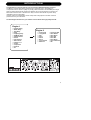
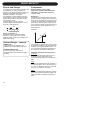
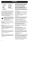
M300
DUAL ENGINE PROCESSOR
USER’S MANUAL
IMPORTANT SAFETY INSTRUCTIONS
The lightning flash with an arrowhead
symbol within an equilateral triangle, is
intended to alert the user to the
presence of uninsulated "dangerous voltage"
within the product's enclosure that may be of
sufficient magnitude to constitute a risk of
electric shock to persons.
The exclamation point within an
equilateral triangle is intended to alert
the user to the presence of important
operating and maintenance (servicing)
instructions in the literature accompanying the
product.
1
2
3
4
5
6
7
Warning!
• To reduce the risk of fire or electric shock,
do not expose this apparatus to rain or
moisture.
• This apparatus must be earthed.
• Use a three wire grounding type line cord
like the one supplied with the product.
• Be advised that different operating voltages
require the use of different types of line
cord and attachment plugs.
• Check the voltage in your area and use the
correct type. See table below:
8
9
10
11
12
13
Read these instructions.
Keep these instructions.
Heed all warnings.
Follow all instructions.
Do not use this apparatus near water.
Clean only with dry cloth.
Do not block any ventilation openings.
Install in accordance with the
manufacturer's instructions.
Do not install near any heat sources such
as radiators, heat registers, stoves, or other
apparatus (including amplifiers) that
produce heat.
Do not defeat the safety purpose of the
polarized or grounding-type plug. A
polarized plug has two blades with one
wider than the other. A grounding type plug
has two blades and a third grounding
prong. The wide blade or the third prong
are provided for your safety. If the provided
plug does not fit into your outlet, consult an
electrician for replacement of the obsolete
outlet.
Protect the power cord from being walked
on or pinched particularly at plugs,
convenience receptacles, and the point
where they exit from the apparatus.
Only use attachments/accessories
specified by the manufacturer.
Unplug this apparatus during lightning
storms or when unused for long periods of
time.
Refer all servicing to qualified service
personnel. Servicing is required when the
apparatus has been damaged in any way,
such as power-supply cord or plug is
damaged, liquid has been spilled or objects
have fallen into the apparatus, the
apparatus has been exposed to rain or
moisture, does not operate normally, or has
been dropped.
Voltage
Line plug according to standard
110-125V UL817 and CSA C22.2 no 42.
220-230V CEE 7 page VII, SR section
107-2-D1/IEC 83 page C4.
240V
•
•
•
BS 1363 of 1984.
Specification for 13A fused
plugs and switched and
unswitched socket outlets.
This equipment should be installed near the
socket outlet and disconnection of the
device should be easily accessible.
Do not install in a confined space.
Do not open the unit - risk of electric shock
inside.
Caution:
You are cautioned that any change or
modifications not expressly approved in this
manual could void your authority to operate this
equipment.
Service
• There are no user-serviceable parts inside.
• All service must be performed by qualified
personnel.
a
IMPORTANT SAFETY INSTRUCTIONS
EMC / EMI.
This equipment has been tested and found to
comply with the limits for a Class B Digital
device, pursuant to part 15 of the FCC rules.
These limits are designed to provide
reasonable protection against harmful
interference in residential installations. This
equipment generates, uses and can radiate
radio frequency energy and, if not installed and
used in accordance with the instructions, may
cause harmful interference to radio
communications. However, there is no
guarantee that interference will not occur in a
particular installation. If this equipment does
cause harmful interference to radio or television
reception, which can be determined by turning
the equipment off and on. The user is
encouraged to try to correct the interference by
one or more of the following measures:
•
•
•
•
Reorient or relocate the receiving antenna.
Increase the separation between the
equipment and receiver.
Connect the equipment into an outlet on a
circuit different from that to which the
receiver is connected.
Consult the dealer or an experienced
radio/TV technician for help.
For the customers in Canada:
This Class B digital apparatus complies with
Canadian ICES-003.
Cet appareil numérique de la classe B est
conforme à la norme NMB-003 du Canada.
b
Certificate Of Conformity
TC Electronic A/S, Sindalsvej 34, 8240
Risskov, Denmark, hereby declares on own
responsibility that following products:
M300 - Dual Engine Processor
- that is covered by this certificate and
marked with CE-label conforms with
following standards:
EN 60065
Safety requirements for mains
(IEC 60065) operated electronic and
related apparatus for household
and similar general use
EN 55103-1 Product family standard for
audio,video, audio-visual and
entertainment lighting control
apparatus for professional
use. Part 1: Emission.
EN 55103-2 Product family standard for
audio, video, audio-visual and
entertainment lighting control
apparatus for professional
use. Part 2: Immunity.
With reference to regulations in following
directives:
73/23/EEC, 89/336/EEC
Issued in Risskov, March 2002
Anders Fauerskov
Chief Executive Officer
TABLE OF CONTENTS
INTRODUCTION
APPENDIX
Table of Contents . . . . . . . . . . . . . . . .3
Introduction . . . . . . . . . . . . . . . . . . . . .5
Front Panel Overview . . . . . . . . . . . . .6
Rear Panel Overview . . . . . . . . . . . . .8
Signal Flow Diagram . . . . . . . . . . . . . .9
Typical M300 Setups . . . . . . . . . . . . .10
MIDI Implementation Chart .
MIDI Continuous Controllers
Reset Procedure . . . . . . . . .
MIDI Bulk Dump . . . . . . . . .
Technical Specifications . . .
.
.
.
.
.
.
.
.
.
.
.
.
.
.
.
.
.
.
.
.
.
.
.
.
.
.
.
.
.
.
.30
.31
.31
.31
.32
BASIC OPERATION
How To Operate the M300
Input/Output Section . . . . . .
The Multi-effects Engine . . .
The Reverb Engine . . . . . . .
Store . . . . . . . . . . . . . . . . .
Recall . . . . . . . . . . . . . . . . .
The Display . . . . . . . . . . . .
Miscellaneous
Factory Presets . . . . . . . . . .
MIDI channel . . . . . . . . . . .
Sysex ID . . . . . . . . . . . . . . .
M300 software . . . . . . . . . .
Routings . . . . . . . . . . . . . . .
.
.
.
.
.
.
.
.
.
.
.
.
.
.
.
.
.
.
.
.
.
.
.
.
.
.
.
.
.
.
.
.
.
.
.
.
.16
.18
.20
.21
.21
.21
.
.
.
.
.
.
.
.
.
.
.
.
.
.
.
.
.
.
.
.
.
.
.
.
.
.
.
.
.
.
.22
.22
.22
.22
.23
EFFECTS
Multi-effects
Dynamic Delay .
Tape Delay . . . .
Studio Delay . . .
Delay . . . . . . . .
PingPong Delay
SlapBack Delay
.
.
.
.
.
.
.
.
.
.
.
.
.
.
.
.
.
.
.
.
.
.
.
.
.
.
.
.
.
.
.
.
.
.
.
.
.
.
.
.
.
.
.
.
.
.
.
.
.
.
.
.
.
.
.
.
.
.
.
.
.
.
.
.
.
.
.
.
.
.
.
.
.
.
.
.
.
.
.
.
.
.
.
.
.
.
.
.
.
.
.24
.24
.25
.25
.25
.25
Phaser . . . .
Tremolo . . .
Chorus . . . .
Compressor
De-Esser . .
.
.
.
.
.
.
.
.
.
.
.
.
.
.
.
.
.
.
.
.
.
.
.
.
.
.
.
.
.
.
.
.
.
.
.
.
.
.
.
.
.
.
.
.
.
.
.
.
.
.
.
.
.
.
.
.
.
.
.
.
.
.
.
.
.
.
.
.
.
.
.
.
.
.
.
.25
.25
.26
.26
.27
.
.
.
.
.
.
.
.
.
.
.
.
.
.
.
Reverbs
Reverb types . . . . . . . . . . . . . . . . . .28
TC Electronic, Sindalsvej 34, DK-8240 Risskov – [email protected]
English Version
Prod. No: E60501601
Rev 3.2 – SW – V 1.00
3
QUICK START If you just can’t wait to hear the great
effects waiting for you in your new M300
Dual Effects processor, follow the few steps
in this quick setup guide:
• Unpack the M300 and check for possible
damages that could have been caused by
transport.
• Read the safety instructions.
• Take a few minutes to register online via:
www.tcelectronic.com or send in the
registration card. Customers registered
online will be notified directly via E-Mail
about new tips&tricks and manual updates.
Consider the M300 as two effects processors in
one box. We call these two processors
“Engines”. The Multi-Effect Engine creates one
of the following effects: Delay, Chorus, Flanger,
Phaser, Tremolo, De-Ess or Compression.
The Reverb Engine creates Reverb.
These two Engines can be used separately or
in conjunction.
Connections & Routing:
The M300 has two routing options that require
two different ways of connecting.
The Routing mode is set on the M300 rear
panel and should correspond to your current
setup.
Serial mode
Dual Send/Return
mode
Serial Routing (switch in OUT position)
- utilizing both effect Engines in serial.
Dual Send/Return (switch in IN position)
- ideal if you need to send signal from two
different AUX sends on your mixer and return
on a stereo Aux or two other channels.
4
IF YOU JUST CAN’T WAIT
For detailed explanations on Routings and
connections please read page 22.
• When all audio connections are made
connect power.
• Set the M300 in Preset Off mode using the
PRESET ON/OFF key:
The M300 is in Preset Off mode when the
display reads as illustrated above.
• Set all controls in 12 o’clock position to
hear factory settings.
(For Dual Send/Return mode set MIX to 100%)
• Select an Effect from the Multi-effects section
• Select a Reverb type from the Reverb
Section.
• Start playing music through the M300.
• Adjust Input level to a level just below the
point where the two INPUT PPMs turn red.
• Set the desired Mix between the Dry and
Wet signal of the entire M300 using the MIX
control.
• Set the desired balance between the MultiEffects section and the Reverb section using
the EFFECT BALANCE knob.
• Now tweak the controls for the two sections
until you have the effects intended.
(When using the Dual Send/Return mode
always set MIX to 100%)
For any questions left unanswered by this
manual feel free to visit our online support
center; TC Support Interactive, which can be
accessed via: www.tcelectronic.com
Latest manual revision can always be
downloaded from www.tcelectronic.com
INTRODUCTION
Congratulations on the purchase of your TC Electronic M300 Dual Engine processor.
The M300 is a Dual Engine effects processor that is extremely easy to use. Making no
compromises when it comes to quality we proudly present the M300 in the affordable price range.
With top quality effects and the intuitive user-interface we are convinced that you will enjoy the
M300 now and in the future. The M300 is so easy to use that this manual may seem nearly
redundant to the front panel itself.
However, read on for explanations of basic setups and routing-options to achieve maximum
performance from your new M300.
The Dual Engine Structure lets you combine various effects with high quality Reverbs.
Engine 1
•
•
•
•
•
•
•
•
•
•
•
•
•
•
•
Dynamic Delay
Studio Delay
Tape Delay
Delay
PingPong Delay
SlapBack Delay
Vintage Phaser
Phaser
Hard Tremolo
Soft Tremolo
Flanger 1 & 2
Chorus
Compressor
De-Esser
Off
Engine 2
•
•
•
•
•
•
•
•
Concert Hall
Living Room
Club
Plate I
Plate II
Spring
“Live” Reverb
Ambience
•
•
•
•
•
•
•
•
TC Classic Hall
Vocal Studio
Vocal Room
Vocal Hall
Drum Box
Drum Room
Large Cathedral
Off
5
FRONT PANEL OVERVIEW
INPUT knob
Adjusts the Input level.
1/L and 2/R LEDS
3 color LEDs indicating Input
level on Left and Right Inputs.
Green :
-40dB
Yellow :
-6dB
Red :
-1dB
MIX knob
Adjusts the mix between the
wet and the dry signal. 100%
“Wet” is achieved at fully
clockwise position.
EFFECTS BALANCE knob
Adjusts the balance between
the Effects Engine and the
Reverb Engine. Maximum
effect from both Engines is
achieved at 12 o’clock
position.
DIGI IN button and LED
LED Off
Digital Input is set to Off. The
M300 processes only the
signal present on the Analog
Inputs.
LED Green
The M300 is locked correctly
to the Digital Input signal.
LED Flashing
Digital In is selected but no
digital signal is received or the
signal is corrupt. The M300
automatically returns to
internal clock and Analog
operation.
6
BYPASS knob and LED
Bypass function varies
depending on the selected
Routing (set on the rear
panel):
Dual Send Return routing:
Bypass operates as “mute”.
Serial routing:
Bypass routes the Input signal
to Output.
MULTI-EFFECT selector
Selects between the 15 effects
& Off in the Multi-effects
Engine.
TIMING knob & TAP key
Tap the global tempo using the
TAP key by tapping quarter
notes. Now use the timing
knob to multiply the tapped
tempo.
The range varies from 0.5 to 2.
Example:
• Tap quarter notes at Tempo
120 BPM. This equals 500
milliseconds.
• The range of the TIMING
knob is 0.5 to 2 giving you a
Delay time varying from:
250ms to 1000ms.
Note that the Slapback
Delay type has a shorter
range as the Slapback
Delay type by nature is a
short Delay.
TIMING knob as
AMOUNT/DRIVE control
For the Compressor and DeEss algorithms (marked with
an “*”) this knob has different
functions:
: Amount
De-Ess
Compressor
: Drive
FEEDBACK/DEPTH knob
Controls the Feedback or
Depth parameter depending of
the selected effect.
Delay
: Feedback
Phaser : Depth
Tremolo : Depth
Flange : Depth
Chorus : Depth
FEEDBACK/DEPTH knob as
FREQ/RATIO control
For the Compressor and DeEss algorithms (marked with
an “*”) this knob has different
functions:
: Frequency
De-Ess
: Ratio
Compressor
-3, -6, -12 LEDs
These LEDs indicate the
applied gain-reduction when
Compressor or De-Ess
algorithms are selected.
It is worth noticing that the
Compressor uses Automatic
Make-up Gain to naturally
compensate for the decreased
gain.
FRONT PANEL OVERVIEW
REVERB Type selector
Selects between 15 different
Reverb types or sets the
Reverb Engine to “Off”.
PRE DELAY knob
Controls the relative Pre Delay
of the selected Reverb.
DECAY knob
Controls the relative Decay of
the selected Reverb.
COLOR knob
Controls the relative Color of
the selected Reverb.
LOAD/HOLD TO STORE key
This key has two functions.
• Press once to load the
preset selected via the
CURSOR UP/DOWN keys.
• Press and hold to store the
current preset.
From “Off” to “On”:
The display starts to blink the
previously recalled preset
number while still processing
according to the front controls.
To actually load the preset
press LOAD.
PRESET ON/OFF key
The M300 has two preset
modes.
Preset “Off” mode:
The display reads as illustrated
above - no numbers.
In this mode the M300 will play
effects according to the front
panel controls.
When going from Preset “On”
to Preset “Off” mode the
effects will always be updated
according to the positions of
the front controls.
Set MIDI channel
Press and hold the PRESET
ON/OFF key approx. 2.5 sec.
Now set the desired MIDI
channel 1 to 16 or “o” for
OMNI (receives on all
channels) or OF for Off, using
the ARROW UP/DOWN keys.
Via this menu a Bulk Dump
can also be performed. (see
page 31).
Press PRESET ON/OFF key
once to exit the MIDI channels
set mode.
Preset “On” mode:
The display reads a specific
preset number.
In this mode you can recall
various user presets by using
the UP/DOWN arrows followed
by LOAD.
(Note that the M300 holds no
stored factory presets apart
from the default settings in the
various effects).
EDITED KNOBS LEDs
The LEDs are relevant in
Preset “On” mode only. They
indicate when the front
controls do not match the
settings in the actually recalled
preset.
ARROW UP/DOWN keys
Scroll between presets when
in Preset “On” mode.
Toggling between the Preset
On/ Preset Off modes
generates two situations:
From “On” to “Off”:
Preset is updated according to
the positions of the front
controls.
7
REAR PANEL
Routing Switch
Balanced
Jack
Analog
Inputs
Balanced
Jack
Analog
Outputs
Digital
S/PDIF
Input/
Output
MIDI
Pedal
In/Out Input
Power
Input
100 - 240V
ROUTING switch
Switches between Dual Send/Return and Serial
Input modes.
Analog Input
Analog Input on 1/4 inch connectors.
Use Left Input for connecting a mono signal.
Dual Send/Return mode:
Switch is In, and Green LED on front is On.
If you connect to Left Input only and use
Dual Send Return mode the Input signal
is fed to both the Multi-effects Engine
and the Reverb Engine, and you can then use
the M300 as two independent effect units with a
common Output.
Serial mode:
Switch is Out and Green LED on front is Off.
Read much more about these Routing options
on pages 22/23. See also the suggested
setups at pages 10-15.
Analog Output
Analog Output is a Stereo Output on two 1/4”
Jack connectors.
Pedal Input
The Pedal Input gives you the possibility to
Bypass and “tap” the Global Tempo via
momentary switches. The Global tempo can be
used to set Delay time.
The connection is a 1/4” Stereo Jack with
Bypass on tip and Tap Tempo on ring.
8
SIGNAL FLOW
MIDI Cable
DIN CONNECTOR
5POLE - MALE
180 degrees
DIN CONNECTOR
5POLE - MALE
180 degrees
max. 10m
SHIELDED CABLE (3 or 5 wires + screen)
Jack Cable
Mono to Mono
TIP
GND
GND
TIP
Jack Cable
Stereo
TIP
RING
GND
GND
RING
TIP
9
TYPICAL SETUPS
Connecting and Setting up the M300
Setting up the M300 is very easy. It is, however, important to connect and setup the M300 correctly
according to your application. Setting up basically means: connecting, selecting one of the two
routing options via the switch on the rear panel and finally setting the MIX control on the front panel.
Find the setup you are about to create or similar on the following two pages - and follow the
instructions.
Setup
M300 Routing Schematic
10
Dual Send/Return
This setup applies to a mixer with two (or
more) AUX sends. It utilizes the two effect
sections in the M300 as two separate effects
with a common Output.
• On the rear panel select DUAL S/R routing
by leaving the switch in the “IN “ position.
• Connect AUX 1 send to the M300 Left Input.
• Connect AUX 2 send to the M300 Right
Input.
• Connect the M300 Left and Right Outputs to
the Stereo AUX L/R returns of either AUX 1
or AUX 2.
• Set MIX to 100% wet, as you in this setup do
not want the direct signal to pass the M300.
• Set Input level to 12 o’clock position.
• Set BALANCE to 12 o’clock position.
• Select Reverb type and Multi-effect type
using the selectors on the front panel.
• Set the AUX Return level on the mixer to
approx. 50%.
• Now slowly turn up the AUX Sends 1 and 2
on the mixer for the channels you wish to
add effect to.
• Adjust/fine-tune the M300 Input level so the
Input LED on the front panel often is Orange
but only rarely peaks at Red color.
TYPICAL SETUPS
Setup
Serial Setup
This setup utilizes the M300 as a Multieffects processor connected in serial to a
Reverb. It is ideal when you wish to add
Reverb to a signal already processed by
one of the Multi-effects. The illustrated
setup is a typical live instrument setup.
• On the rear panel select SERIAL routing by
leaving the switch in “OUT “ position.
• Connect Line signal directly from your
instrument or from a DI-box to the M300
Inputs. (use Left Input for mono signals).
• Connect the M300’s Left and Right Outputs
to mixer or amplification.
• Set Input level to 12 o’clock position.
• Set MIX level to 12 o’clock position.
• Set BALANCE to 12 o’clock position.
• Adjust/fine-tune the M300 Input level so the
Input LED on the front panel often is Orange
but only rarely peaks at Red color.
• Select Reverb type and Multi-effect type
using the selectors on the front panel.
• Now fine-tune:
- MIX between wet and dry signal
- BALANCE between the two effect Engines.
M300 Routing Schematic
11
TYPICAL SETUPS
Setup
Routing Schematic
“Parallel Setup” (analog Input only)
This setup utilizes the M300 as a Dual
processor on a mono signal with a common
stereo Output.
• On the rear panel select Dual S/R routing by
leaving the ROUTING switch in the “IN “
position.
• Connect AUX1 (or any) to Left Input.
NO connections to Right Input. The Left Input
signal is automatically fed to the Right Input
internally in the M300.
• Connect the M300 Left and Right Outputs to
the Stereo AUX L/R returns of either AUX 1
or AUX 2.
• Set MIX to 100% wet, as you in this setup do
not want the direct signal to pass through the
M300.
• Set Input level to 12 o’clock position.
• Set BALANCE to 12 o’clock position.
• Select Reverb type and Multi-effect type
using the selectors on the front panel.
• Set the AUX Return level on the mixer to
approx. 50%.
• Now slowly turn up the AUX Sends
• Adjust/fine-tune the M300 Input level so the
Input LED on the front panel often is Orange
but only rarely peaks at Red color.
Controlling M300 via MIDI
Various functions in the M300, such as
preset recall and Tap Tempo, can be
controlled via an external MIDI device.
This example shows how to control the
M300 with a TC Electronic G•Minor*
footcontroller. A complete list of CC values
can be found on page 31.
• Connect MIDI Out on the G•Minor to MIDI In
on the M300.
• Connect MIDI Out on the M300 to MIDI In on
the G•Minor.
You are now able to recall the stored presets in
the M300 using the UP/DOWN switches on the
G•Minor. You can also tap the Global Tempo
using the HOLD switch.
* Detailed information on the G•Minor can be
found in the G•Minor manual. Feel free to
download from www.tcelectronic.com
12
TYPICAL SETUPS
Setup
Guitar Setups
This setup utilizes the M300 as a Multieffects processor connected in serial to a
Reverb. It is ideal when you wish to add
Reverb to a signal already processed by
one of the Multi-effects.
This is a typical guitar setup.
• On the rear panel select SERIAL routing by
leaving the switch in the “OUT “ position.
• Connect guitar to preamp Input.
• Connect preamp Output to M300 Left Input.
• Connect M300 Left Output to Input on your
amp. Use the regular Input or the Return on
an effect loop if you use Combos or Heads. If
you are using a regular Power-amp and
speakers simply use the Inputs.
• Set Input level to 12 o’clock position.
• Set MIX level to 12 o’clock position.
• Set BALANCE to 12 o’clock position.
• Adjust/fine-tune the M300 Input level so the
Input LED on the front panel often is Orange
but only rarely peaks at Red color.
• Select Reverb type and Multi-effect type
using the selectors on the front panel.
• Now fine-tune:
- MIX between wet and dry signal
- BALANCE between the two effect Engines.
Setup
M300 in an effects loop
• On the rear panel select SERIAL routing by
leaving the switch in “OUT “ position.
• Connect guitar to amp Input.
• Connect effect-loop send to M300 Left Input.
• Connect M300 Left Output to Effect-loop
Return.
• Set Input level to 12 o’clock position.
• If the effects loop is serial type (see owners
manual for the amp) set MIX level to 12
o’clock position.
If the effects-loop is parallel type set MIX to
100% (fully clockwise position).
• Set BALANCE to 12 o’clock position.
• Adjust/fine-tune the M300 Input level so the
Input LED on the front panel often is Orange
but only rarely peaks at Red color.
• Select Reverb type and Multi-effect type
using the selectors on the front panel.
• Now fine-tune:
- BALANCE between the two effect Engines.
13
TYPICAL SETUPS
Digital Setup
- M300 as Insert
This setup is ideal if you are using the M300
as a digital insert effect on your harddisk
recording system.
This setup requires that you are using an
I/O card with S/PDIF In/Out.
• Select Serial Routing by leaving the
ROUTING switch on the rear panel in Out
position.
• Connect the M300 S/PDIF digital Out to the
Digital Input on your soundcard.
• Connect the Digital Out on your soundcard to
the Digital In on the M300.
• Set your Soundcard to act as Master clock.
There can be different names for this setting
but “Internal Clock”, “Internal Sync” or
“Master“ are commonly used phrases.
(This is probably setup via you harddisk
recording program. Please refer to owners
manual)
• Press the DIGI IN button on the M300.
• If the DIGI IN LED is green, the M300 is
locked correctly on the Digital Input signal.
• If the LED is flashing Digital In is selected but
no digital signal is received within 5 seconds
or the signal is corrupt.
The M300 automatically returns to internal
clock and analog operation but will continue
to look for digital signal and the DIG IN LED
on the front panel will keep blinking.
Check cables and make sure that your
Soundcard is set as Master.
• Once setup you can use the M300 as a
plugin on your harddisk recording mixer.
14
TYPICAL SETUPS
Digital Setup
- M300 as A to D converter
The analog to digital converters in the M300
are superior to most converters used on
soundcards in the affordable price range.
You can therefore most likely benefit from
using the M300 as an A to D converter when
doing harddisk recordings.
Feed the M300 with an analog Input e.g.
from you mixer or Instrument line signal,
and you are feeding a high quality digital
signal to the harddisk.
If you wish you can of course add effects to
the tracks while recording but the essence
of this setup is to get best possible A to D
conversion by skipping the A to D
converters on your soundcard.
• Select Serial or Dual S/R Routing via the
ROUTING switch on the rear panel.
Note that if you do not add effects to the
tracks while recording and uses Bypass
mode you must use Serial routing.
• Feed any analog signal to the analog Input
on the M300.
• Connect the M300 S/PDIF digital Out to the
Digital Input on your soundcard.
• The M300 must act as Master clock in this
setup and you must therefore set your
Soundcard to act as Slave.
There can be different names for this setting
but “External Clock”, “External Sync” or
“Slave“ are commonly used phrases.
(This is probably setup via your harddisk
recording program. Please refer to owners
manual).
• For pure A to D conversion with no effects
added, both Effect Type Selectors should be
set to Off.
• Adjust Input level gain using the INPUT level
knob.
15
OPERATING - INPUT/OUTPUT SECTION
INPUT
This knob controls the Input level for both the
Analog and Digital Input options. For optimal
performance of the M300 a well-adjusted Input
level is essential.
LED Off
Digital Input is set to Off. The M300 processes
only the signal present on the Analog Inputs.
This is done on an internal Sample Rate of
44.1kHz.
Analog Input Range
Counter Clockwise : -10dB
Center
:
0dB
Clockwise
: +14dB
LED Green
The M300 is locked correctly on the Digital
Input signal. With the digital signal a clock is
supplied. The M300 can lock on either a 44.1
or a 48kHz Sample Rate frequency which are
the most commonly used Sample Rate
frequencies. E.g. a regular CD is 44.1kHz.
Digtal Input Range
Counter Clockwise : -18dB
Center
:
0dB
Clockwise
: +6dB
1/L - 2/R INPUT LEDs
These LEDs signal with three colors.
Green : Indicating that you are “well on the
safe side”
Yellow : Reaching optimal performance.
Red
: Should only occasionally blink at
absolute peaks in the material you
feeding the M300 with.
The Input knob adjusts the level for both Left
and Right Input channels. If there is a
significant difference between the Input of the
Left and Right channels you should adjust the
Output of the device feeding the M300.
DIG. IN
The M300 has analog as well as digital Input
options. The digital Input is the S/PDIF type
connected via RCA phono cables.
To select/deselect the Digital Input press the
DIG IN button once.
The green LED next to the DIG IN button will
indicate various situations.
16
Flashing LED
If Digital In is selected but no digital signal is
received or the signal is corrupt the M300
automatically returns to internal clock and
Analog operation. However, the M300 will
continue to look for digital signal on the S/PDIF
Input and this is indicated by the flashing LED.
If you wish to stay in analog mode press DIG
IN once and the LED will stop flashing.
Dual S/R On - LED
When this LED is lit (green) it is indicated that
the Dual Send/Return Routing is selected via
the switch located on the rear panel.
Read more about the Dual Send/Return mode
on page 22-23.
OPERATING - INPUT/OUTPUT SECTION
MIX
Sets the mix between dry and wet signal. The
Mix parameter operates differently depending
on the selected routing:
In "Dual S/R" Routing, "Mix" controls the overall
wet/dry mix of both the Multi-effect and the
Reverb section.
In "Serial" Routing, "Mix" functionality in the
"Effects" section depends on the selected
effect.
BYPASS
The Bypass function operates differently
depending on the selected routing.
Dual Send/Return routing:
Bypass key operates as a Mute function.
Serial routing:
Here the Bypass function simply passes the
source signal unprocessed to Output.
EFFECTS BAL.
Sets the balance between the two Engines.
Both Engines have maximum Output in 12
o'clock position.
Fully clockwise or counter-clockwise settings
can be considered as 100% bypass of one of
the Engines.
17
THE MULTI-EFFECTS ENGINE
Multi-Effects Engine
Effect Selector
With the EFFECT selector you select between
one of the following effects and Off.
•
•
•
•
•
•
•
•
Dynamic Delay
Studio Delay
Tape Delay
Delay
Ping Pong
SlapBack
Vintage Phaser
Phaser
•
•
•
•
•
•
•
•
De-Esser
Compressor
Chorus
Flanger 1
Flanger 2
Soft Tremolo
Hard Tremolo
Off
-12dB, -6dB, -3dB Gain Reduction LEDs
These LEDs indicate the applied Gain reduction
in the Compressor and De-Esser algorithms.
TAP key and TIMING knob
Delay Effects:
The tempo of the Delay effects is set using both
the TAP key and the TIMING knob.
By tapping the TAP key you set a “global
tempo“ that you can increase/decrease using
the TIMING knob that operates as a multiplier
in the Delay algorithms.
The range of the TIMING knob is 0.5 to 2.
18
Example
Let us say that you tap quarter notes in tempo
120BPM using the TAP key. With the TIMING
knob in 12 o’clock position you now have a
Delay time off 500ms*.
If you turn the TIMING knob fully counterclockwise the actual Delay time will be
0.5 times 500ms= 250ms
If you turn the TIMING knob fully clockwise the
tempo will be:
2 times 500ms=1000ms (1 second)
When powering up the M300 the default Tempo
is 120BPM, but as explained above the position
of the TIMING knob defines the actual tempo.
*The nature of a Slapback Delay is very short
Delay times and the range of this Delay type is
therefore much shorter.
THE MULTI-EFFECTS ENGINE
TIMING knob - De-Ess and Compression:
For the De-Ess algorithm the TIMING knob
controls the Amount parameter.
For the Compressor algorithm the TIMING knob
controls the Drive parameter.
TIMING knob - Chorus, Flanger, Phaser and
Tremolo:
Increases/decreases the Tempo.
Remember that the default setting suggested
by TC Electronic is achieved by setting the
knob in 12 o’clock.
FEEDBACK/DEPTH
- FREQUENCY/RATIO knob
This knob changes functionality with the
selected algorithms.
The knob controls the Feedback parameter in:
All Delays
The knob controls the Depth parameter in:
Chorus
Flanger
Phaser
Tremolo
The knob controls the Frequency parameter in:
De-Ess
The knob controls the Ratio parameter in:
Compressor
For further details on these parameters
please read the Multi-effects chapter on
pages 24-27.
19
THE REVERB ENGINE
Reverb Engine
Reverb Selector
Select between the following Reverb types or
“Off”.
•
•
•
•
•
•
•
•
Concert Hall
Living Room
Club
Plate I
Plate II
Spring
“Live” Reverb
Ambience
•
•
•
•
•
•
•
•
Classic Hall
Vocal Studio
Vocal Room
Vocal Hall
Drum Box
Drum Room
Large Cathedral
Off
To hear the carefully designed default settings
for each of the Reverb types set PRE DELAY,
DECAY and COLOR knobs in “12 o’clock”
position (neutral). Then adjust and fine-tune to
the given application.
It is worth noticing that the range of each of
these parameters will vary from algorithm to
algorithm.
As an example it is possible to set a much
longer Decay time for a Classic or Concert Hall
Reverb than for a Drum Box.
20
Pre Delay
A short Delay placed between the direct signal
and the Reverb Diffuse Field. By using Pre
Delay the source material is kept clear and
undisturbed by the more diffuse Reverb Field
arriving shortly after.
Decay
The Decay parameter determines the length of
the Reverb Diffuse Field. The length is defined
as the time it takes for the Reverb to decay
approximately 60dB.
Color
Varies the “color” of the Reverb. From dark to
crisp and bright the Color parameter can really
change the characteristics and style of the
Reverb.
STORE - RECALL & M300THE DISPLAY
Edited knobs LEDs
Preset Modes
Display
The M300 holds two significantly different
modes. To toggle between these modes press
the PRESET ON/OFF key.
Edited knobs LEDs
(relevant only in Preset ON mode)
These LEDs refer to the 10 front panel controls.
See illustration above.
They indicate when the front controls do not
match the current settings of the active preset.
“Preset On” mode
In this mode it is possible to load any of the
previously stored presets.
The “Preset On” mode is active when the
display shows location numbers from 1 to 99.
If you try to load a preset from a location
where no preset is stored - no action will
take place.
“Preset Off” mode
In Preset Off mode the M300 will process the
signal according to the position of the front
controls. A “what you see is what you hear” setting.
Once you have accessed the Preset Off
mode and return to the Preset On mode
the preset number will blink indicating
that you must press LOAD to recall the
settings stored with that particular
preset.
When you turn any of the knobs and pass the
position physically matching the current
parameter value, the parameter is “grabbed”,
the LED goes off and you can adjust the
parameter.
Load/Store Presets
Load User Preset
• Enter “Preset On” mode using the PRESET
ON/OFF key. The M300 is in Preset On
mode when the display shows locationnumbers 1 to 99.
Use the UP/DOWN arrows to select desired
preset (1-99).
• The digits are now blinking to indicate that
you are previewing the preset and it has not
yet been recalled.
• Press LOAD to recall the preset and the
digits are now steady.
Store User Preset
• Enter “Preset On” mode using the PRESET
ON/OFF key. The M300 is in Preset On
mode when the display shows locationnumbers 1 to 99.
• Use the UP/DOWN arrows to select desired
preset location where you intend to store the
preset (1-99).
• The digits are now blinking to indicate that
you have not yet stored the preset.
• Press the LOAD (HOLD TO STORE) key for
approx. 2.5 seconds until the digits turn steady.
21
MISCELLANEOUS
Factory Presets
The M300 holds no conventional factory
presets. When all the controllers are in 12
o'clock position the M300 is in "neutral",
meaning that all parameters are set as
suggested by TC Electronic. Combining the 16
positions of both the Multi-effect and Reverb
selectors you actually have 256 “factory”
presets.
MIDI CH.
Via an external MIDI device it is possible to
recall presets and control parameters in the
M300. For the external device to communicate
with the M300 it is essential that they
communicate on the same MIDI Channel.
The M300 can be set to receive on all MIDI
channels, none or all.
• Press and hold PRESET ON/OFF. The
current selected MIDI channel is displayed.
Assuming the M300 is “right out of the box” or
that you have performed a Reset procedure as
described on page 31, the display now shows:
- indicating that channel 1 is selected and the
M300 can receive MIDI information on
channel 1.
• Use the UP/DOWN arrows to select MIDI
channels 1 to 16.
• “O” indicates Omni which means that the
M300 can recive MIDI information on all
channels.
• “OF” indicates that the M300 will ignore any
incoming MIDI messages.
• Press LOAD to verify and exit menu.
SysEx ID
The M300 SysEx ID is always identical with the
set MIDI Channel.
22
Application Software version
This number indicates the current loaded
application software and is relevant only for
sevicing purposes.
• Press and hold PRESET ON/OFF and use
the UP/DOWN arrows to select “AP” as
displayed below.
The display will flash between “AP” (for
application) and the current loaded application
software.
Front Software version
This number indicates the current loaded front
software and is relevant only for sevicing
purposes.
• Press and hold PRESET ON/OFF and use
the UP/DOWN arrows to select “Fr” as
displayed below.
The display will flash between “Fr” (for
front-software) and the current loaded front
software number.
ROUTINGS
It is essential that you have selected the correct
routing according to your setup:
Serial Routing
With this routing the two Engines are used as a
line of two effects where the signal first passes
the Multi-effects Engine and thereafter the
Reverb Engine.
This is the Routing to select when you want to
add reverb to a signal after the signal is
processed by the Multi-Effects Engine.
On the rear panel you select Serial Routing and
you should connect the M300 according to this
illustration:
Parallel Routing (analog Input only)
This routing gives you the opportunity to have
two effects in parallel on a single mono signal.
• Select Dual Inputs Routing by leaving the
ROUTING switch on the rear panel in “In”
position.
• Connect a mono signal to Left Input.
The Input signal is now split and fed to both the
Multi-effects Engine and the Reverb Engine.
Both Engines then uses Left and right Outputs
as common Outputs.
Signal Flow:
Connect the M300 according to this illustration:
Dual Send/Return
By routing two different signals to the two effect
Engines you can utilize the M300 as two
separate effect units with a common Output.
Also see Setup examples on pages 10 to 15.
Use this if you e.g. wish to use the M300 to add
Delay to a guitar on one channel and Reverb to
a vocal on another channel.
23
MULTI-EFFECTS
This manual section explains the function of the front panel controls as well as the algorithm
parameters in the Multi-effects section.
Delay - controls
TIMING knob
Both the TIMING and the TAP keys are
used to specify the desired tempo of the
repeats.
A tempo is tapped on the TAP key and with
the TIMING knob you multiply this tempo.
The range of the TIMING knob is 0.5 to 2.
See example below
FEEDBACK knob
The FEEDBACK knob sets the number of
Delay repeats. Leaving the knob in
12 o’clock position gives you the starting
point suggested by TC Electronic.
Example - TIMING knob
Let us just explore the Tap Tempo and Timing
functions a bit further:
With a Studio Delay algorithm selected you tap
quarter notes in tempo 120BPM using the TAP
key. With the TIMING knob in 12 o’clock
position you now have a Delay time of 500ms.
If you turn the TIMING knob fully counter-clock
wise the actual Delay time will be:
0.5 times 500ms= 250ms
If you turn the TIMING knob fully clockwise the
tempo will be:
2 times 500ms=1000ms (1 second)
24
When powering up the M300 the default
Tempo is 120BPM, but as explained the
position of the TIMING knob defines the
actual tempo.
You should also note that the range varies
depending on the selected Delay type.
E.g. - as a short Delay time is what defines a
Slapback Delay, the range is considerably
lower than in any other Delay algorithm.
When using the M300 in a Dual Send/
Return setup the MIX knob should be set
to 100% wet.
Delay Types
Dynamic Delay
The Dynamic Delay initially introduced in the
well-recognized TC 2290, is a function that
allows the Delay Output level to be actively
altered by the dynamics of the Input level.
The basic idea is to have a lower level of the
Delay repeats while the instruments are played
(or vocals are sung) and an increased level of
Delay when no Input is present.
A function that leaves the source material clear
and undisturbed while played and delicately
accompanied by the Delay between phrases.
With the correct settings you will be amazed
how you can use Delay effects on material
where you previously never considered this an
option.
MULTI-EFFECTS
Tape Delay
This algorithm emulates the old style Tape
Delays. Before the Digital era Delays were
created using a Tape Recording device with a
tape-loop and recording/playback heads.
As you probably know analog tape-recorders
has a tendency to deteriorate/change the
recorded material. Wow and flutter combined
with a significant loss of high-end frequencies,
and to some extent also low-end frequencies,
are all elements commonly associated with
tape recordings. However, these features are at
times quite useful and sought-after as they in
some situations blend with and compliments
the source material in a highly musical manner.
Among other things the M300 Tape Delay uses
a HiCut with a rather low Cross-over frequency
to emulate the loss of highs found on
conventional Tape delays.
Compare this to the clean Studio Delay
algorithm, which has a considerably higher
HiCut frequency to see what fits your
application.
Studio Delay
As opposed to the Tape Delay algorithm
described above the Studio Delay algorithm will
give you a clearer reproduction of the material
fed to the M300. To soften the Delay as it is
commonly done in studio productions the
Studio Delay uses a subtle yet significant HiCut
at a relatively High crossover frequency.
Delay
Standard Delay. The M300 processing power
and excellent 24 bit converters will process a
precise high quality Delay with no deterioration
of the sound.
PingPong Delay
The PingPong Delay basically pans the Delay
repeats from left to right and back while
keeping the Input signal at its original position.
This gives a very wide spread special effect.
Slapback Delay
Slapback Delay is a very short Delay with only
a single or a few repeats. The effect is
commonly used as a “doubling-effect” making
the processed material seam more massive.
Short Slapback Delays are also often used on
funky rhythm guitars, - a bit longer on
Rockabilly guitar or vocals.
Phaser
Phaser and Vintage Phaser
The Vintage Phaser utilizes four all-pass filters.
These filters create comb-looking characteristics.
When the filtered sound is mixed with the direct
sound the “phasing sound” occurs.
The Standard Phaser utilizes twelve all-pass
filters. Due to the higher number of filters in the
Smooth Phaser, compared to the Vintage
Phaser, the Standard Phaser simply sounds
smoother than the Vintage type.
Phaser - controls
TIMING knob
In the Phaser algorithm the TIMING knob
sets the Speed of the Phaser.
FEEDBACK/DEPTH knob
In the Phaser algorithm the
FEEDBACK/DEPTH knob sets the Depth of
the Phasing effect.
Hard Tremolo/Soft Tremolo
A Tremolo is basically a repeated level change
controlled by an LFO. The M300 offers a Hard
Tremolo that used a “square” wave-shape and
Soft Tremolo that use a “triangular” wave
shape. Please see the illustration below. The
difference is quite obvious. Listen and enjoy!
Hard Tremolo - Square shape
Soft Tremolo - Triangular shape
Tremolo - controls
TIMING knob
In the Tremolo algorithm the TIMING knob
sets the Speed of the Tremolo.
FEEDBACK/DEPTH knob
In the Tremolo algorithm the
FEEDBACK/DEPTH knob sets the Depth of
the Tremolo effect.
25
MULTI-EFFECTS
Chorus and Flanger
Compressor
A Chorus/Flanger is basically a short Delay that
is modulated by an LFO (Low Frequency
Oscillator). The difference between Chorus and
Flanging is the applied Delay time and the
Feedback parameter in the Flanger.
The modulation of the short Delay gives very
small variations in pitch. These pitch changes
blended with the direct sound gives you the
Chorus/Flanger sound.
A Chorus effect is typically used as a
smoothing effect where the Flanger is more in
the genre of “special effects”.
Before explaining how the M300
Compressor operates a little background
information on compression in general
could be useful.
Speed
Background
A Compressor is basically used to reduce the
dynamic content of a signal. When the signal is
above the set Threshold the Compressor starts
to reduce the Output level according to the set
Ratio. With a reduced dynamic range a signal
is much easier to further control and will have a
more precise and “fixed” appearance in any
audio production.
Depth
Illustration:
Flanger 1 and Flanger 2
The difference lies in a few fixed settings.
Flange 2 is more intense due to a higher
Feedback setting, a lower HiCut setting and a
higher Delay setting.
Chorus/Flanger - controls
TIMING knob
In the Chorus/Flanger algorithms the
TIMING knob sets the Speed of the effect.
FEEDBACK/DEPTH knob
In the Chorus/Flanger algorithm the
FEEDBACK/DEPTH knob sets the Depth of
the effect.
Compression is a powerful tool. Correct amount
of compression applied on specific instruments
will create a homogen well-defined result. Too
much compressing applied will generally give
an un-dynamic, less musical and flat result.
Parameters associated with Compression
Threshold
As soon at the Input signal is above the set
Threshold point the Output level of the
Compressor will be reduced by the specified
Ratio.
Ratio
Specifies how aggressive the gain reduction of
the signal should be. With a ratio setting of e.g.
4:1- for every 4dB that is above the Threshold
point only 1 is passed to the Output.
Attack
Specifies how fast the gain reduction specified
by the Ratio parameter should be applied. The
Attack parameter in the M300 Compressor is
fixed.
26
MULTI-EFFECTS
Auto Make-up gain
Since the Output of the signal above the set
Threshold point is reduced the entire signal will
appear to be at a lower volume. In many
Compressors and also in the Compressor type
used in the M300, Auto Make-up gain will
compensate for this loss of gain.
This way the Output level is kept and only the
dynamic range is changed.
The M300 Compressor
For optimal “ease of use” we have simplified
and reduced the conventional Compression
controls into the following controls:
Drive (TIMING KNOB)
The higher the Drive setting is, - the lower
the Threshold point is set and the harder
you will “hit” the Compressor. In other words:
The higher Drive setting, the more
compression is added.
De-Esser
A De-Esser is a compressor type used to
reduce only specific sibilant frequencies.
Typically the “s” sounds can be far too
dominant in a vocal track and the track would
therefore often benefit from being processed by
a De-Esser.
De-Esser Controls
Amount (TIMING KNOB)
Sets the amount of gain reduction around
the Frequency specified by the Frequency
knob.
Frequency (FEEDBACK/DEPTH KNOB)
Sets the Frequency around which you would
like to reduce frequencies.
Ratio (FEEDBACK/DEPTH KNOB)
This parameter sets the amount of gain
reduction of signal above the “Threshold” see Drive parameter.
27
REVERBS
The M300 holds the following Reverb types:
•
•
•
•
•
•
•
•
Concert Hall
Living Room
Club
Plate I
Plate II
Spring
“Live” Reverb
Ambience
•
•
•
•
•
•
Classic Hall
Vocal Studio
Vocal Room
Vocal Hall
Drum Box
Large Cathedral
Each of these Reverb types are created and
fine tuned by the highly experienced staff at TC
Electronic and utilizes the vast experience we
have accumulated over the past years of
producing high quality Reverbs. Though the
M300 is a very compact effects unit in the
affordable price range there is no compromise
when it comes the Reverb quality.
To get best starting points for your
application set the three controls in
the Reverb section in 12 o’clock
position and “take a trip” round the
different Reverb types.
By leaving the controls in 12 o’clock position
you will hear our suggested settings for each
Reverb type.
Once you have the Reverb type closest to your
goal start twisting the controls.
Pre Delay
A short Delay placed between the direct signal
and the Reverb Diffuse field. By using Pre
Delay the source material is kept clear and
undisturbed by the more diffuse Reverb Diffuse
Field arriving shortly after.
Decay
The Decay parameter determines the length of
the Reverb Diffuse Field. The length is defined
as the time it takes for the Diffuse Field to
decay approximately 60dB.
Color
Varies the “color” of the Reverb. From dark to
crisp and bright the Color parameter can really
change the characteristics and style of the
Reverb. Try it!
28
Perception of Reverb types may vary from
person to person. It is a rather subjective
issue to discuss, describe or even define.
However, over the years a general
perception of basic Reverb types has
evolved. From these definitions the
experienced sound-engineer chooses and is
given good starting points for various
applications. We choose to briefly describe
the Reverb types found in the M300 like this:
TC Classic Hall
The TC Classic Hall simulates a rather large
Hall and preserves the natural characteristics of
the source material.
This is excellent for many studio applications
requiring medium to long Decay times and
especially on vocal material.
Concert Hall
Compared to the TC Classic Hall the Concert
Hall is a more diffuse Reverb type. This type of
Reverb is often used on drums and other
percussive material. We are still talking a
simulation of a rather big facility.
Vocal Room - Vocal Studio - Vocal Hall
The three types all simulates typical vocal
recording facilities. The Vocal Studio and Vocal
Room types are medium sized locations. They
give the soft type of reflections usually
associated with wooden surfaces.
The Vocal Hall is a larger location than the
above but still with the soft characteristics of
wooden surfaces.
Drum Box - Drum Room
Reverbs especially designed to emulate the
typical recording rooms used for drums.
The Drum Box is a 80’s style ambient room
with only very short reflections.
The Drum Room emulates the reflections in a
medium sized drum room with a high ceiling giving longer but natural sounding reflections
compared to the Drum Box.
Large Cathedral
Where the TC Classic Hall, and to some extent
also the Concert Hall, are Reverbs with smooth
diffuse fields, the Large Cathedral has a much
more uneven diffused field. Emphasis on the
reflections deriving from many hard surfaces
and the high amount of Lo Color naturally
occurring in this type of rooms, gives excellent
simulation of the Large Cathedral.
REVERBS
Living Room
Directly opposite the Large Cathedral the Living
Room type simulates a relatively small room
well furnished. In such a room many reflections
are absorbed by soft material and source
material is reflected and sustained only from
walls (with wallpaper) and windows and maybe
a table etc.
Club
Did you ever discover the great difference of a
soundcheck and the actual concert. The Club
Reverb emulates a typical empty medium sized
club. Try this on vocals or guitar as an effect
that will put emphasis on these instruments.
Plate I and II
Before the digital era either reverberating
springs or large metallic plates was used to
create Reverb. The characteristics of Plate
Reverbs are diffuse and bright and are still
successfully used on many percussive
instruments.
Spring
The Spring algorithm is designed to reproduce
the sound of the old spring Reverbs, such as
the ones used in vintage guitar amps.
Live
For live purposes a rather grainy and bright
Reverb is needed to cut through the typical
background noise at live locations. The Live
Reverb is optimal when used with medium to
long Decay times and will work excellent on
both vocals and instruments requiring a clear
and obvious Reverb.
Ambience
With focus on the Early Reflections that defines
the perception of a room size, the Ambience
Reverb type is typically used on dry recordings
or dry drum samples to emulate a feeling of
environment. Ambience and Room definition
are the keywords here.
29
APPENDIX - MIDI IMPLEMENTATION CHART
DUAL ENGINE PROCESSOR M300 - APRIL 2002
Function
Basic Channel
Transmitted
1
1-16
Recognized
1
OMNI-1-16
X
X
Pitch Bend
Control Change
X
X
X
X
X
X
X
O
X
X
X
X
X
X
X
O
Prog Change
O
O
SysEx
Common
O
X
X
O
X
X
X
O
X
X
X
X
X
X
X
X
X
X
Mode
Default
Changed
Default
Messages
Altered
Note Number
Velocity
After Touch
True Voice
Note ON
Note OFF
Key’s
Channel
Song Pos
Song Sel
Tune
System real time Clock
Aux Messages
O:YES
X:NO
30
Commands
Local ON/OFF
All Notes OFF
Active Sense
Reset
Mode 1: OMNI ON, POLY
Mode 3: OMNI OFF, POLY
Mode 2: OMNI ON, MONO
Mode 4: OMNI OFF, MONO
Remarks
See CC list on page 31
for details.
All Controllers are
Single Byte type scaled
to parameter range.
MIDI TimeClock can be
used to set Delay tempo.
APPENDIX -
MIDI CC & RESET & BULK DUMP
Via an external MIDI device sending MIDI
Control Changes you are able to control the
parameters listed below.
Parameter
Control Change
number:
In Level
Mix
Effect Bal.
Digi. In
Bypass
12
13
14
15
81
MultiEff. Type
MultiEff. Off
Timing
Tap
Feedback
50
82
16
80
17
Rev. Type
Rev. Off
PreDelay
Decay
Color
51
83
18
19
20
MIDI Bulk Dump
By performing a MIDI bulk dump you are able
to dump all presets to an external MIDI device
such as a sequencer for backup.
• Press and hold the PRESET ON/OFF key
approx. 2.5 sec.
• Use the ARROW UP/DOWN keys to select
Bulk Dump mode.
The display will show:
• Set the receiving device in MIDI bulk receive
mode. A standard MIDI sequencer program
should typically be set to record a MIDI track.
(Please refer to the user manual of the
receiving device).
• Now press LOAD once, and the MIDI Bulk
Dump is performed.
The M300 is always ready to receive a
MIDI bulk dump unless the receive MIDI
channel is set to off “OF”
Reset Procedure
If you would like to do a complete reset of the
M300 and return to factory settings follow this
procedure:
• Power down by disconnecting the power
cord.
• Press and hold TAP while reconnecting
power. The display will show a flashing “R”.
• Press Load to reset.
• Power off - power on.
The unit is now reset.
Be aware that all User presets will be
lost when performing a factory reset!
31
APPENDIX
- TECHNICAL SPECIFICATIONS
Digital Input and Output
Connector:
Formats:
Sample Rates:
Processing Delay:
Frequency Response DIO:
Analog Inputs
Connectors:
Impedance, Bal / Unbal:
Max. / Min. Input Level
@ 0 dBFS:
Sensitivity Range
@ 12 dB headroom:
A to D Conversion:
A to D Delay:
Dynamic Range:
THD:
Frequency Response:
Crosstalk:
Analog Outputs
Connectors:
Impedance Bal / Unbal:
Max. Output Level:
D to A Conversion:
D to A Delay:
Dynamic Range:
THD:
Frequency Response:
Crosstalk:
EMC
Complies with:
Safety
Certified to:
RCA Phono (S/PDIF)
S/PDIF (24 bit), EIAJ CP-340, IEC 958
44.1 kHz. (48 kHz only @ Digital Input)
0.08 ms @ 48 kHz
DC to 23.9 kHz ± 0.01 dB @ 48 kHz
1/4" phone jack balanced, mono sense
21 kOhm / 13 kOhm
+24 dBu / 0 dBu
-12 dBu to +12 dBu
24 bit, 128 x oversampling bitstream
0.70 ms / 0.65 ms @ 44.1 kHz / 48 kHz
typ < -92 dB, 22 Hz to 22 kHz
typ < -90 dB (0.0032 %) @ 1 kHz, -1 dBFS
+0/-0.1 dB, 20 Hz to 20 kHz
typ < -100 dB, 20 Hz to 20 kHz
1/4" phone jack balanced
40 Ohm / 20 Ohm
+14 dBu
24 bit, 128 x oversampling bitstream
0.68 ms / 0.63 ms @ 44.1 kHz / 48 kHz
typ < -105 dB typ, 22 Hz to 22 kHz
typ < -97 dB (0.0014 %) @ 1 kHz, +13 dBu
+0/-0.5 dB, 20 Hz to 20 kHz
typ < -100 dB, 20 Hz to 20 kHz
EN 55103-1 and EN 55103-2
FCC part 15, Class B, CISPR 22, Class B
IEC 65, EN 60065, UL6500 and CSA E60065
CSA FILE #LR108093
Environment
Operating Temperature:
Storage Temperature:
Humidity:
32° F to 122° F (0° C to 50° C)
-22° F to 167° F (-30° C to 70° C)
Max. 90 % non-condensing
Control Interface
MIDI:
Pedal:
In/Out: 5 Pin DIN
1/4" phone jack
General
Finish:
Anodized aluminum front
Plated and painted steel chassis
Display:
Dimensions:
Weight:
2 x 7 segment + LED's
19" x 1.75" x 4.2" (483 x 44 x 105.6 mm)
3.3 lb. (1.5 kg)
Mains Voltage:
Power Consumption:
Warranty Parts and labor:
100 to 240 VAC, 50 to 60 Hz (auto-select)
<15 W
1 year
Due to continuous development these specifications
are subject to change without notice.
32