1
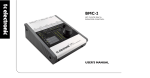
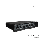
Desktop Konnekt 6
User’s Manual
English Version
IMPORTANT SAFETY INSTRUCTIONS
The lightning flash with an arrowhead symbol within an
equilateral triangle is intended to alert the user to the
presence of uninsulated “dangerous voltage” within the
product's enclosure that may be of sufficient magnitude
to constitute a risk of electric shock to persons.
1
2
3
4
5
6
7
8
9
10
11
12
13
14
Read these instructions.
Keep these instructions.
Heed all warnings.
Follow all instructions.
Do not use this apparatus near water.
Clean only with dry cloth.
Do not block any ventilation openings. Install in accordance
with the manufacturer's instructions.
Do not install near any heat sources such as radiators, heat
registers, stoves, or other apparatus (including amplifiers) that
produce heat.
Do not defeat the safety purpose of the polarized or groundingtype plug. A polarized plug has two blades with one wider than
the other. A grounding type plug has two blades and a third
grounding prong. The wide blade or the third prong are
provided for your safety. If the provided plug does not fit into
your outlet, consult an electrician for replacement of the
obsolete outlet.
Protect the power cord from being walked on or pinched
particularly at plugs, convenience receptacles, and the point
where they exit from the apparatus.
Only use attachments/accessories specified by the
manufacturer.
Use only with the cart, stand, tripod, bracket, or table
specified by the manufacturer, or sold with the
apparatus. When a cart is used, use caution when
moving the cart/apparatus combination to avoid injury
from tip-over.
Unplug this apparatus during lightning storms or when unused
for long periods of time.
Refer all servicing to qualified service personnel. Servicing is
required when the apparatus has been damaged in any way,
such as cord or plug is damaged, liquid has been spilled or
objects have fallen into the apparatus, the apparatus has been
exposed to rain or moisture, does not operate normally, or has
been dropped.
The exclamation point within an equilateral triangle is
intended to alert the user to the presence of important
operating and maintenance (servicing) instructions in the
literature accompanying the product.
Warning!
•
•
•
•
•
To reduce the risk of fire or electrical shock, do not expose this
apparatus to rain or moisture and objects filled with liquids,
such as vases, should not be placed on this apparatus.
This apparatus must be earthed.
Use a three wire grounding type line cord like the one supplied
with the product.
Be advised that different operating voltages require the use of
different types of line cord and attachment plugs.
Check the voltage in your area and use the correct type.
See table below:
Voltage
Line plug according to standard
110-125V UL817 and CSA C22.2 no 42.
220-230V CEE 7 page VII, SR section
107-2-D1/IEC 83 page C4.
240V
BS 1363 of 1984. Specification for 13A
fused plugs and switched and
unswitched socket outlets.
•
•
•
•
•
This equipment should be installed near the socket outlet and
disconnection of the device should be easily accessible.
To completely disconnect from AC mains, disconnect the power
supply cord from the AC receptacle.
The mains plug of the power supply shall remain readily operable.
Do not install in a confined space.
Do not open the unit – risk of electric shock inside.
Caution:
You are cautioned that any change or modifications not
expressly approved in this manual could void your authority to
operate this equipment.
Service
•
•
There are no user-serviceable parts inside.
All service must be performed by qualified personnel.
a
EMC / EMI & CERTIFICATE OF CONFORMITY
EMC/EMI
This equipment has been tested and found to comply
with the limits for a Class B Digital device, pursuant to
part 15 of the FCC rules.
These limits are designed to provide reasonable
protection against harmful interference in residential
installations. This equipment generates, uses and can
radiate radio frequency energy and, if not installed and
used in accordance with the instructions, may cause
harmful interference to radio communications. However,
there is no guarantee that interference will not occur in a
particular installation. If this equipment does cause
harmful interference to radio or television reception,
which can be determined by turning the equipment off
and on, the user is encouraged to try to correct the
interference by one or more of the following measures:
•
•
•
•
Reorient or relocate the receiving antenna.
Increase the separation between the equipment and
receiver.
Connect the equipment into an outlet on a circuit
different from that to which the receiver is connected.
Consult the dealer or an experienced radio/TV
technician for help.
For Customers in Canada:
This Class B digital apparatus complies with Canadian
ICES-003.
Cet appareil numérique de la classe B est conforme à la
norme NMB-003 du Canada.
Certificate of Conformity
TC Electronic A/S, Sindalsvej 34, 8240
Risskov, Denmark, hereby declares on own
responsibility that the following product:
Desktop Konnekt 6
that is covered by this certificate and
marked with CE-label conforms with
following standards:
EN 60065
Safety requirements for mains
(IEC 60065) operated electronic and
related apparatus for household
and similar general use
EN 55103-1 Product family standard for
audio,video, audio-visual and
entertainment lighting control
apparatus for professional use.
Part 1: Emission.
EN 55103-2 Product family standard for
audio, video, audio-visual and
entertainment lighting control
apparatus for professional use.
Part 2: Immunity.
With reference to regulations in following
directives:
73/23/EEC, 89/336/EEC
Issued in Risskov, March 2008
Mads Peter Lübeck
Chief Executive Officer
b
TABLE OF CONTENTS
INTRODUCTION
APPENDIX
Safety Instructions . . . . . . . . . . . . . . . . . . . . . . . . .a
FAQ . . . . . . . . . . . . . . . . . . . . . . . . . . . . . . . . . . . . .30
EMC/EMI & Certificate of Conformity . . . . . . . . . .b
Shortcut Keys . . . . . . . . . . . . . . . . . . . . . . . . . . . . .30
Table of Contents . . . . . . . . . . . . . . . . . . . . . . . . . .3
Tips . . . . . . . . . . . . . . . . . . . . . . . . . . . . . . . . . . . . .30
Introduction . . . . . . . . . . . . . . . . . . . . . . . . . . . . . .4
Updating Software . . . . . . . . . . . . . . . . . . . . . . . . .30
Quick Setup Guide . . . . . . . . . . . . . . . . . . . . . . . . .6
Firewire Bus Power Notes . . . . . . . . . . . . . . . . . . . .31
Technical Specifications . . . . . . . . . . . . . . . . . . . . .32
TYPICAL SETUPS
Mic + Instrument . . . . . . . . . . . . . . . . . . . . . . . . . . . .7
Instrument + Instrument . . . . . . . . . . . . . . . . . . . . .8
Stereo In . . . . . . . . . . . . . . . . . . . . . . . . . . . . . . . . . .9
OVERVIEW
Front Panel Overview . . . . . . . . . . . . . . . . . . . . . . .10
Rear Panel Overview . . . . . . . . . . . . . . . . . . . . . . . .13
TC NEAR
Mixer Page . . . . . . . . . . . . . . . . . . . . . . . . . . . . . . . .14
M40 Studio Reverb . . . . . . . . . . . . . . . . . . . . . . . . .16
Setup Page . . . . . . . . . . . . . . . . . . . . . . . . . . . . . . .19
System Settings - System page . . . . . . . . . . . . . . .21
System Settings - WDM page . . . . . . . . . . . . . . . .26
KONNEKT AND CUBASE
Konnekt and Cubase . . . . . . . . . . . . . . . . . . . . . . .28
TC Electronic, Sindalsvej 34, DK-8240 Risskov – [email protected]
English Version
Manual revision 1.1 – SW – V 1.00
3
INTRODUCTION
Desktop Konnekt 6 - the shortest distance between your music and capturing it
FireWire Audio Interface | Monitor Control
Desktop Konnekt 6 offers the same high quality recording features as the other interfaces of the Konnekt product family, but
in a desktop design that allows you to focus on performance rather than technology. Bundled with Cubase LE4, Desktop
Konnekt 6 has all the features you need to instantly record instruments and vocals into your Mac or PC.
Once you get started recording, you’ll immediately treasure the benefits of Desktop Konnekt 6. Packed into this interface are
features such as an ergonomic volume knob for total control of input and monitoring levels, high resolution meters for visual
level read out, a studio reverb that will warm up your headphone mix while you’re recording, and a high quality IMPACT™
preamp for top-notch sound quality.
Desktop Konnekt 6’s unique design not only makes it fit perfectly onto your desktop for easy operation, it will also make you
want to leave it right next to your laptop – just for its great looks.
Hands-on Design
Operational simplicity just doesn’t come any easier. The intuitive design of Desktop Konnekt 6’s user interface means no
tedious manual reading before you’re up and running.
Big Control
Desktop Konnekt 6’s volume control is always within reach when you need it. If you have ever accidentally blasted a nonmuted signal from your host application through a pair of active speakers, you’ll soon learn to appreciate this knob as your (or
your neighbors’) savior.
IMPACT™ - Integrated Mic PreAmp Circuit Technology
TC is renowned for its mic preamps, notably ranking among the finest mic preamps on the market. Desktop Konnekt 6 comes
with an IMPACT™ preamp, making the recording of a vocal or instrument pure joy. Also equipped with the same instrument
inputs used in TC’s high-end guitar processors, Desktop Konnekt 6 offers studio quality recordings regardless of the source.
High Resolution Meter
Desktop Konnekt 6’s high resolution meter puts critical information right where you need it. The three modes allow you to use
the meter for input, output, or mastering purposes.
M40 Studio Reverb
Included with the Desktop Konnekt 6 is the M40 Studio Reverb – a simple to use, great sounding reverb that is powered by
AlgoFlex™, a new high definition TC technology that enables hardware quality and predictability to be ported to native
software. It is available for tracking to increase the recording comfort without tying the effect to the final take, operated by the
control panel and the reverb knob on the front panel of Desktop Konnekt 6.
4
DESKTOP KONNEKT 6 FEATURES
The M40 Studio Reverb is also available as a natively running VST/AU plug-in, allowing you to use it as part of your session in
your PC or Mac.
SOFTWARE INSIDE
TC Near Control Panel with direct monitor mixer and reverb control
Cubase LE4
EFFECT INSIDE
M40 Studio Reverb for PC and Mac - Powered by AlgoFlex™
FEATURES
•
•
•
•
•
•
•
•
•
•
•
•
•
•
•
•
•
•
•
•
Big volume control
IMPACT™ mic preamp with 48v phantom power
High-resolution meter
M40 Studio Reverb powered by AlgoFlex™
Direct monitor control with input/DAW control
Headphone out with separate level control and separate source
Input configuration: Microphone + Instrument / Instrument + Instrument / Stereo line
True Hi-Z guitar inputs known from TC’s high-end guitar processors
Balanced stereo outputs
TC NEAR™ compatible: works with all other Konnekt products
Instant scene recall
DIM switch for convenient speaker dimming
Intuitive control panel for direct monitoring control
VST/AU compatible
Desktop design
FireWire 1394, bus powered
DICE™ digital interface chip with JetPLL™ jitter elimination technology
Low latency drivers for Mac and PC, WDM, ASIO and CoreAudio
24-bit/192 kHz sampling rate
Cubase LE4 included.
5
QUICK SETUP GUIDE
UP AND RUNNING IN TEN MINUTES
This quick-guide will help you set up the Desktop Konnekt
6 in a typical application. For further details please refer to
later sections of this manual.
Unpacking
•
•
•
•
•
•
•
Open the box from the top and remove cabling.
Lift out the styrofoam insert, then lift out the Desktop
Konnekt using both hands.
Remove the Konnekt from its plastic bag.
Inspect your Konnekt for signs of transit damage.
In the unlikely event of transit damage having occurred,
inform the carrier and the supplier.
Keep all the packaging if damage has occurred, as this
will show evidence of excessive handling force.
It is also a good idea to keep the packaging for future
transportation.
* We recommend running your Konnekt(s) on a dedicated FireWire bus.
If your computer has one or more FireWire connections on the chassis
they will typically run on the same FireWire bus. You may connect the
Konnekt to one of these. If you intend to run additional FireWire
devices simultaneously, for example an external hard drive, we
recommend running each device on its own, separate bus.
This separate bus would typically be on an installed FireWire PCI card.
Note that such a FireWire PCI card typically has three ports, but these
ports also operate on a single bus.
Software installation
•
•
•
The software MUST be installed before connecting the
Konnekt.
Refer to the Konnekt Installation Guide supplied in the
package and on the Konnekt DVD.
If you are familiar with software installation procedures
in general, you may simply insert the accompanying
DVD-ROM in your computer’s DVD drive and follow the
instructions.
Check contents
TC Near Control Panel
The package should contain the following items:
• Konnekt audio interface
• Power supply
• FireWire cable
• DVD with software etc.
• Konnekt Installation Guide
When the Konnekt drivers have been installed correctly,
you can open the TC Near Control Panel.
COMPUTER REQUIREMENTS
Mac
•
•
•
•
PowerPC (1 GHz or higher) or Intel CPU
256 MB RAM
FireWire (IEEE 1394) port
OS X 10.4.11 or 10.5
Windows
•
•
•
•
6
Pentium 4, 1.6 GHz or faster
256 MB RAM
FireWire (IEEE 1394) port
Windows XP or Vista 32 bit
On Mac computers:
/Applications/TC Near
You may also start the application from System
Preferences.
On Windows computers:
Press: Start/Programs/TC Electronic/TC Near
The TC Near Control panel can also be accessed via
Windows’ control panel section.
We encourage you to ensure that you have the latest
software and manual version by visiting our website
at www.tcelectronic.com.
TYPICAL SETUPS: MICROPHONE + INSTRUMENT
1
Desktop Konnekt 6 – Rear Panel
front of the computer using headphones, simply
because of using the big volume knob is more comfortable.
This is the rear panel view of the Desktop Konnekt 6.
2
Active Monitors
4
3
Headphones
Use this jack to connect a set of headphones. You have
a couple of choices when it comes to controlling the
level of the headphones output. By default, the PHONES
knob on the front panel controls the phones level.
However, via the Setup page it is possible to link the
phones level to the big volume knob on the front panel.
Notice that when the big volume knob is assigned to
controlling the headphones level, the PHONES knob
still sets the max headphones level.
Separate level control is ideal such as when you are in
the control-room and a singer in the recording room
needs a different headphone level.
Linked level control is ideal if you record yourself in
Computer
Use the Desktop Konnekt 6 with a laptop or desktop
computer with a FireWire interface. Please read the
“System requirements” section in this manual for
information on minimum requirements.
In this setup, we use a set of active monitors connected
to the Monitor outputs. Of course, you can also connect
your Desktop Konnekt 6 to a pair of channels on a mixer
or directly to a hi-fi amplifier instead.
5
Microphone
Connect either a dynamic or a condenser microphone
to your Desktop Konnekt 6. If you use a condenser
microphone, the +48 option in the channel strip on the
TC Near mixer page must be enabled. Depending on
the output level of the connected instrument, you may
need to activate the boost function in the channel strip
on the TC Near mixer page.
6 Guitar
Connect a guitar, a bass or a line level instrument to the
LINE/INST RIGHT jack. The instrument inputs are Hi-Z,
meaning you can connect any electric guitar or bass,
whether active or passive.
7
TYPICAL SETUPS: DUAL INSTRUMENT
1
Desktop Konnekt 6 – Rear Panel
Separate level control is ideal such as when you are in
the control-room and a singer in the recording room
needs a different headphone level.
Linked level control is ideal if you record yourself in
front of the computer using headphones, simply
because of using the big volume knob is more
comfortable.
This is the rear panel view of the Desktop Konnekt 6.
2
Active Monitors
In this setup, we use a set of active monitors
connected to the Monitor outputs. Of course, you can
also connect your Desktop Konnekt 6 to a pair of
channels on a mixer or directly to a hi-fi amplifier instead.
4
3
Headphones
Use this jack to connect a set of headphones. You have
a couple of choices when it comes to controlling the
level of the headphones output. By default, the
PHONES knob on the front panel controls the phones
level. However, via the Setup page it is possible to link
the phones level to the big volume knob on the front
panel.
8
Computer
Use the Desktop Konnekt 6 with a laptop or desktop
computer with a FireWire interface. Please read the
“System requirements” section in this manual for
information on minimum requirements.
5
Instruments
Connect a guitar, a bass or a line level instrument here.
TYPICAL SETUPS: STEREO IN
1
Desktop Konnekt 6 – Rear Panel
Separate level control is ideal such as when you are in
the control-room and a singer in the recording room
needs a different headphone level.
Linked level control is ideal if you record yourself in
front of the computer using headphones, simply
because of using the big volume knob is more
comfortable.
This is the rear panel view of the Desktop Konnekt 6.
2
Active Monitors
In this setup, we use a set of active monitors
connected to the Monitor outputs. Of course, you can
also connect your Desktop Konnekt 6 to a pair of
channels on a mixer or directly to a hi-fi amplifier instead.
3
4
Headphones
Use this jack to connect a set of headphones. You have
a couple of choices when it comes to controlling the
level of the headphones output. By default, the
PHONES knob on the front panel controls the phones
level. However, via the Setup page it is possible to link
the phones level to the big volume knob on the front
panel.
Computer
Use the Desktop Konnekt 6 with a laptop or desktop
computer with a FireWire interface. Please read the
“System requirements” section in this manual for
information on minimum requirements.
5
Stereo Source
Here, we have connected a keyboard as a stereo
source.
9
FRONT PANEL OVERVIEW
1
Gain 1/Gain 2 – Input Gain Trim
Use these controls to set the appropriate input level.
Set meters to “Input” using the Meter switch button
(12). Then adjust the Gain 1 and Gain 2 trims until the
meters show a level as close to “0 dB” as possible
without clipping.
2
Input Overload LEDs
Green: A signal is present on the inputs.
Yellow: Indicates that the level is just above -6 dB.
10
Ideally the yellow color should flash at peaks.
Red: Indicates that the signal is too hot. Reduce the
output level on the source device or turn down the In
Gain.
3
On LED (Reverb)
When this LED is lit, the M40 Studio Reverb is active.
Turning down the REVERB knob (7) to minimum
position switches off the reverb. Turn the REVERB knob
clockwise and the reverb is automatically turned on.
FRONT PANEL OVERVIEW
4
Scene Select: Mic + Inst(rument)
With the Mic+Instrument scene selected, a microphone
can be connected to the XLR MIC input and used in
combination with a line level instrument connected to
the LINE/INST RIGHT input (1/4" jack connector).
5
8 Input/DAW Mix
This is a very easy way of setting the monitor mix level
between the signal on the inputs of the Desktop
Konnekt (including the added reverb from M40), and
the signal coming from your DAW (e.g. Cubase LE4).
When the Input/DAW knob is turned fully clockwise
(DAW Mix), you can do the monitor mix inside your
DAW. This will, however, introduce a delay (latency)
between the computer and the Desktop Konnekt 6.
The length of this delay depends on your buffer
settings.
With the Desktop Konnekt 6, this issue can be
resolved by setting the Input/DAW mix to fx. 50%
and turning off the DAW monitor mix.
Scene Select: Dual Inst(rument)
With the Dual Instrument scene selected, you can
connect two different instruments (or other line level
signals) to the LINE/INST LEFT and LINE/INST RIGHT
1/4" jack inputs. The signals are processed
individually. This scene is typically used if you want to
record two mono instruments at the same time, e.g. a
guitar and a bass.
6 Scene Select: Stereo In
Select this option if you want to connect a stereo signal
– such as a synthesizer – to the left and right
LINE/INST 1/4" jack inputs.
When you work with a variety of recording sources,
you do not have to change the routing every time:
You can leave microphone and instruments
connected to the three recording inputs all the time.
Input selection is done using the SCENE buttons.
7
settings for the Reverb are made in the Reverb Panel on
the Mixer page of the TC Near Control Panel.
Reverb
This knob controls the return level from the M40 Studio
Reverb. Notice that when the knob is turned fully
counter-clockwise, the reverb is “off”. When set to
“off”, the reverb will not use any CPU power. All
9
Monitor Section
Panel: Press this button to maximize/minimize the TC
Near Control Panel on your computer monitor.
Mono: Press this button to run the MONITOR outputs in
mono. When the LED is off, Stereo mode is selected.
When the LED is on, Mono mode is selected.
Dim: Use this button to alternate between the level set
by the master volume control and a lower (dimmed)
level. The “dim level” is set on the Setup page of the TC
Near Control Panel.
10 Power On/Off
Press this button once to power the Desktop Konnekt 6
on. Press and hold for approximately one second to
power off.
11
FRONT PANEL OVERVIEW
11 Phones level
Individual levels can be set for the Phones and Monitor
outputs. This knob sets the output level for the Phones
out. It is also possible to link the phones level output
to the big volume knob. This option can be selected on
the Setup page of the TC Near Control Panel.
Single flash: If your setup includes several Desktop
Konnekt 6 units, you can alter between
these by selecting the relevant tab in the
TC Near Control Panel. When selecting a
Konnekt unit, the blue LED on that unit
gives a single flash to identify that this
is the Konnekt you have selected.
12 Meter Select (In/Pre/Post)
This switch allows you to switch between metering the
signal at three different stages.
Input: When this LED is lit, the meters show the signal
level at the input. The best signal to noise ratio is
achieved when the input signal only occasionally peaks
at “0”. Adjust the level on the sending device and set
the in-gain of the Desktop Konnekt 6 using the GAIN 1
and GAIN 2 knobs.
14 Master Volume
This is the master volume control for monitor outputs.
The knob has red LEDs inside indicating the level. The
higher the setting, the more intense the red light.
The light can be disabled completely via the
Setup page if you prefer.
15 Meters
Pre: When this LED is lit, the meters show the sum of
the following signals:
- Input signal after the gain trims
- Reverb output
- DAW output.
Post: When this LED is lit, the meters show the level on
the MAIN outputs after the master volume control.
13 FireWire/Power LED Indicator
When the Desktop Konnekt 6 is hooked up via FireWire,
the blue LED can indicate the following states:
12
Steady lit:
Status OK
Flashing:
Uploading, hardware error or FireWire
communication error.
Off:
The Konnekt has no connection to the
driver, maybe because the driver is not
installed.
Three color LED meters.
Green:
Yellow:
Red:
-60 to -9 dB
-9 to 0 dB
Overload
REAR PANEL OVERVIEW
1
2
Power In
4
Use the power-supply supplied with the product or a
power-supply with equivalent specifications. (12V DC 0.3 Amp).
These are the balanced main outputs of the Desktop
Konnekt. Connect them to a set of active speakers
(such as Dynaudio Acoustics BM series), to an
amplifier with passive speakers or to a mixer.
FireWire connector
This is an IEEE 1394 connector for connecting the
Desktop Konnekt 6 to a computer.
The Desktop Konnekt can be bus-powered via FireWire
if your computer supports bus power. Please refer to
the Appendix section of this manual.
Before plugging in the FireWire connector, make
sure that the plug is positioned correctly (not
upside-down).
3
Phones Out
This is a 1/4" TRS jack connector for headphones. The
phones output level is set using the PHONES knob.
However, you can also assign the big volume knob to
control the phones level if you prefer. This is set up via
the Setup page in the TC Near Control Panel. Notice that
the PHONES knob will always set the max phones level.
5
Monitor Output
Recording Inputs
– Use the two LINE INST 1/4" jack connectors for linelevel or Hi-Z instruments to connect line-level
instruments, electric or acoustic guitars directly.
– You may connect a microphone to the XLR connector
and benefit from the Desktop Konnekt’s IMPACT™ mic
pre-amp renowned for its high quality. 48V phantom
power for condenser microphones can be activated via
the Mixer page in the TC Near Control Panel. For
microphones with a particular low output, the Boost
should be activated. This is also done via the Control
Panel’s Mixer page.
If you want to, you can leave a microphone and your
instruments connected to the three recording inputs
all the time. Input selection is done using the SCENE
buttons.
Warning!
Excessive sound pressure from earphones and
headphones can cause hearing loss.
13
MIXER PAGE
CONTROL PANEL
•
•
Press the Mixer tab to enter the Mixer page.
To change position of knobs and faders: Press and hold
the left mouse button and move the mouse up or
down.
In this section of the Mixer page, you select between three
scenes.
Scenes are “setup presets” that include:
- 48V on/off
- Boost on/off
- Pan button position
- Effects send button position
- Reverb settings.
As soon as a scene is changed, the new settings will be
assigned to that scene. There is no additional store
procedure.
1 – Scene – MIC+INST
The MIC (XLR) and the LINE/INST RIGHT inputs are
selected.
2 – Scene – INST+INST
The LINE/INST RIGHT and LINE/INST LEFT instrument inputs
are selected. The two channels are treated as two separate
mono channels.
3 – Scene – STEREO IN
The LINE/INST RIGHT and LINE/INST LEFT instrument inputs
are selected. The two channels are treated as a stereo
input.
When you work with a variety of recording sources,
you do not have to change the routing every time:
You can leave microphone and instruments
connected to the three recording inputs all the time.
Input selection is done using the SCENE buttons.
14
MIXER PAGE
CHANNEL STRIPS
9 – Labels
4 – Meter Section (for both channels)
The mixer-channels have default labels. However, these
can be altered as you wish. Simply click on the channel
label and enter a name of your choice.
The meter indicates the input level. The best signal to
noise ratio is achieved when peaks are as close to 0 dB as
possible without clipping. Adjust the gain using the GAIN
knobs on the Desktop Konnekt 6 and the output level of
the external source.
5 – Pan/Balance
When the “Mic+Inst” or the “Inst+Inst” scene is selected,
this knob acts as the pan control for a channel.
When the “Stereo In” scene is selected, this knob acts as a
balance control between left and right channel.
6 – Send
This is the Effects Send knob for the M40 Studio Reverb.
MICROPHONE CHANNEL
The following parameters are relevant for the microphone
channel only.
7 – 48V Phantom Power
Activate 48V phantom power when connecting a condenser
microphone to the Desktop Konnekt 6.
8 – Boost
For microphones with a particularly low output, the Boost
should be activated. This will boost the signal by 12 dB.
15
M40 STUDIO REVERB
The M40 Studio Reverb is an easy-to-use reverb for both monitoring and mixing. The reverb exist in two variations:
A - as a standard VST/AU plug-in that can be used just as any other VST/AU plug-in from your DAW host application. Notice
that the M40 Studio Reverb is copy protected by the Desktop Konnekt 6. If the Desktop Konnekt 6 is not attached to the
computer, the plug-in will be disabled.
B - as a part of the TC Near Control Panel where it can be used as an excellent cue reverb for the recording artist. In this
situation it is worth noticing that the TC Near Control Panel MUST be open for the reverb to run.
MeterHoldTime:
This parameter sets how long the OVERLOAD LED will
be lit after an overload is detected.
MeterHoldFall:
This parameter sets how fast the meter should fall back
to normal metering after the OVERLOAD LED has been
invoked.
1
Input Meter
This is the input meter for the M40 Studio
Reverb.
Click on the meter using the left mouse button
to select various meter options.
MeterFallback:
This parameter sets how fast the meter should
fall back after peaks. The more dBs per second,
the faster the meter falls back.
16
M40 STUDIO REVERB
2
File
This state indicates that the settings in both memory
locations A and B are identical – so there is actually
nothing to compare.
Pressing the File button will open the File menu that
allows you to load or save a preset.
As soon as you touch one of the parameters, the
memory location “A” will be active – and highlighted.
All parameter changes will be applied to memory
location “A”. If you switch to memory location “B”, you
go back to the starting point, and all further changes
will now be applied to memory location “B”.
Every time you press the A/B button, you will toggle
between these two memory locations.
Load
By selecting “Load”, you can navigate to any folder on
the system, including shared folders. By default, you
will be directed to the default file location.
Save
By selecting “Save”, you can save your preset to any
folder on the system that you have write access to,
including any shared folder. By default, presets are
saved to the default location for the TC Near Control
Panel presets.
My Presets
This menu item provides easy access to your own
presets. Notice that only presets located in the default
file locations for the TC Near Control Panel will be
visible in the drop down menu.
3
A/B
The A/B memory locations are temporary settings
only! Saving a preset will save the currently selected
memory location only. The setting of the other
(hidden) memory location will not be saved!
4
5
Output Meter
This is the output meter for the M40 Studio Reverb (see
also descriptions of the parameters MeterFallBack,
MeterHoldTime and MeterHoldFall in the “1 – Input
meter” section).
6 Preset Name
This is the name of the currently recalled preset. Scroll
through presets using the up/down arrows on the right
side of the name display.
With the A/B compare function you can easily compare
different parameter settings when working with the plug-in.
When you start working on a preset, neither A or B is
highlighted.
Reset
Click the “Reset” button to clear the memory slots A/B
and return to the originally recalled preset.
7
Algorithm
This is the currently selected reverb algorithm. The
available options are Hall, Room and Plate.
17
M40 STUDIO REVERB
8 Algorithm Select buttons
12 Mix
Press to select one of the following three algorithms:
Hall: The Hall reverb simulates a rather large hall while
preserving the natural characteristics of the source
material. This is excellent for many studio applications
requiring medium to long decay times and especially
on vocal material.
Room: The Room algorithm simulates a relatively small,
well furnished room. In such a room, many reflections
are absorbed by soft materials, and the sound is
reflected and sustained only by the walls, windows and
maybe some furniture. The Room reverb will work well
on almost all instruments.
9
This is a dry/wet mix control for the reverb. You should
use the “mix” option when you are using the M40
Studio Reverb as an insert effect on a track in your
DAW.
13 100%
Deactivates the mix control and sets a 100% wet mix.
This is the setting to use when you are using the M40
reverb as a send effect, and also when using it as a cue
reverb for recording. When using the M40 Studio
Reverb in the TC Near Control Panel, always enable
100%. In 100% mode the MIX knob is grayed out.
Notes on the M40 Studio Reverb
Plate: Prior to the digital era, either reverberating
springs or large metallic plates were used to create
reverb. Plate reverbs typically have a very diffuse and
bright sound. The Plate reverb algorithm can be used
with great effect on many percussive instruments.
•
Pre Delay
•
•
The Pre Delay parameter defines a short delay placed
between the direct signal and the reverb diffuse field.
By using a pre-delay, the source material is kept clear
and undisturbed by the more diffuse reverb diffuse
field arriving shortly after.
10 Decay Time
The decay parameter determines the length of the
reverb diffuse field. The length is defined as the time it
takes for the diffuse field to decay approximately by 60 dB.
The M40 Studio Reverb is available only when the TC
Near Control Panel is open.
The M40 Studio Reverb does not consume any CPU
power when the reverb is inactive. The Reverb is
inactive when the REVERB LED on the Desktop Konnekt
is “off”.
The display indicates “Power off” when the REVERB
button on the Desktop Konnekt 6 is turned fully counter
clockwise.
•
The display indicates “Disabled” when the Reverb
Disabled function is activated on the Setup page.
•
The M40 Studio Reverb is not available at quad speed
sample rates (176.4 kHz and 192 kHz.
11 Hi Color
The Hi Color parameter changes the “color” of the
reverb. From dark to crisp and bright, the Hi Color
parameter can really change the characteristics and
style of the reverb.
18
SETUP PAGE
OUTPUT
1
Speaker Dim Level
On the Desktop Konnekt 6’s front panel, you will find the
DIM button. The dim function allows you to instantly switch
to a lower level. Set the desired “dim level” using this knob.
HEADPHONES
This is where you select which source you want to monitor
in the headphones.
2
Headphones Source – Main Mix
Select “Main Mix” to monitor the signal from your DAW
(FireWire channels 1+2) and the physical inputs on
Desktop Konnekt 6.
3
Headphones Source – DAW (Firewire Channels 3-4)
Select “DAW (Firewire Channels 3-4” to route an individual
signal from the computer to the headphones.
This is a function often used e.g. by DJ’s.
To set this up, select this option and assign FireWire
channels 3+4 (called “Phones”) from your host application.
4
Headphone control
When the “Headphone control” option is not
checked, the big VOLUME knob on Desktop
Konnekt 6 controls the master volume on the
Monitor outputs and the PHONES knob controls
the headphones level.
19
SETUP PAGE
When the “Headphone control” option is
checked, the big VOLUME knob on the Desktop
Konnekt 6 controls both the master volume on
the Monitor outputs and the phones level.
Notice that the PHONES knob still sets the
maximum phones out level.
UTILITY
7
Reverb Control
- Reverb to Main Output & Reverb to Phones Output
Select “Reverb to Main Output” to send the reverb to the
main outputs.
Select “Reverb to Phones Output” to send the reverb to the
phones output.
You can use both options, one or none.
If, for example, you want to use the M40 Studio
Reverb as cue reverb for the recording artist’s
headphones but hear a dry signal in the control
room, select the “Reverb to Phones Output” option
only.
Master Level Knob
Master Level Backlight: If you prefer, you can disable the
red light in the big MASTER LEVEL knob by unchecking this
option.
STAND ALONE CLOCK SETTINGS
These settings handle the clock settings when the Desktop
Konnekt 6 operates as a stand-alone unit. As soon as the
Desktop Konnekt 6 is disconnected (FireWire LED off),
these stand-alone clock settings take effect.
REVERB
Notice that the M40 Studio Reverb is not available
when the Desktop Konnekt 6 operates as a standalone unit.
6 Reverb Control – Disable Reverb
The M40 Studio Reverb can be activated/deactivated using
the REVERB knob on the Desktop Konnekt 6.
However, if you prefer to disable the reverb completely,
simply check the “Disable Reverb” box on the Setup page.
8 Sync Source
Desktop Konnekt 6 has no digital I/Os. Therefore,
“Internal” is selected per default and cannot be altered.
9
Disabling the Reverb Control will of course have no
influence on the VST/AU version of the M40 Studio Reverb.
The reverb section on the mixer page will then show:
20
Sample Rate
The following options are available:
44.1 kHz
48 kHz
88.2 kHz
96 kHz
SYSTEM SETTINGS
The following description of the System Settings page is generic for all members of the Konnekt product family. Some of the
described parameters are relevant for specific Konnekt models only. These parameters are marked! Also notice that the
System Settings page handles all units connected as part of your setup.
21
SYSTEM SETTINGS – SYSTEM PAGE
BUFFER SIZE
1
4
The Sync Source parameter determines to which input
the Clock Master should sync. The DICE II™ FireWire
chip provides excellent clock, and in many setups the
“internal” option is the best choice. However, you may
sync to any digital device attached to the digital inputs
of a Konnekt in your system and benefit from the
outstanding JetPLL jitter elimination technology also
provided by the DICE II™ chip.
* The Desktop Konnekt 6 has no digital inputs.
System
Click this field to enter the page holding the system
settings.
2
ASIO Buffer Size (relevant for PCs only)
The buffer size* can be set from 32 to 8192 samples.
The default buffer size is set to 512 samples. The driver
latency is also indicated in ms (milliseconds).
The displayed latency is the driver latency only!
To calculate the complete latency in your setup you
need to add the latency of converters, host (DAW),
and plug-ins.
You should only increase the buffer size if you
experience problems such as clicks and pops in the
sound.*
*
Sync Source
Example 1: Studio Konnekt 48 as Clock Master:
Relevant for PC version only. On Mac computers, the buffer
size is set in the audio application. For instance, in Logic Pro
go to Audio/Hardware drivers to set the buffer size.
Note - clicks and pops in the sound may also derive from clock
problems. These should be resolved first.
SYSTEM CLOCK
3
Clock Master
With the Clock Master parameter, you select which
Konnekt unit in your setup will act as the System Clock
Master.
In a digital setup, it is important that all connected
devices run at the same sample rate. The Clock Master
device defines this sample rate, and distributes a
digital clock based on this sample rate to all devices in
the setup. There can be one, and only one clock master
in a digital setup, and you cannot select your computer
here: The clock master device is always your audio
interface. However, the Clock Master device may sync
to an external device if it has one or more digital
inputs.* See “Sync Source” below.
22
Setting Clock Master and Sync Source
•
The setup consists of two Studio Konnekt 48 units
connected via FireWire, a computer and an ADAT
interface.
• We assigned the nicknames “SK48 No1” and SK48
No2” to the two Studio Konnekt 48 units (Nicknames
are set on the Setup page).
The intention is to sync the entire setup to the ADAT
interface.
SYSTEM SETTINGS - SYSTEM PAGE
•
•
Set Clock Master on the System Settings page to “SK48
No1” as this is the physical Konnekt unit that will
determine the clock master.
Set Sync Source to ADAT as this is the connection on
the Clock Master unit that you would like to sync to.
That is basically it. The Sample Rate should only be set if
“Internal” is selected as clock source.
•
The R4000 is connected to the other Konnekt in the
setup (SK48 No2) and it is set to slave to “SPDIF 1/2”.
5
Sample Rate
Example 2: Studio Konnekt 48 – Jitter Elimination
(This example is not relevant for the Desktop Konnekt 6.)
44.1 kHz
48 kHz
88.2 kHz
96 kHz
176.4 kHz
192 kHz
In this setup, we have a CD player in the system. In terms
of digital clocking, a CD player cannot be controlled
externally and can thus only act as master.
Again we have to stress that not only does Studio Konnekt
48 provide a high quality clock, but it also facilitates
excellent jitter-elimination that will clean up a less-thanperfect digital signal from an external source such as a CD
player.
•
•
The CD player is connected to “SK48 No1” via Tos-link
(optical SPDIF).
“SK48 No1” is selected as Clock Master on the System
Settings page, and the Sync Source parameter is set to
“Optical SPDIF”.
Typically, the sample rate is set within your host
application. If, for example, you play a 44.1 kHz project,
the sample rate automatically shifts to 44.1 kHz. If you
later load and play a 48 kHz song, the sample rate shifts to
48 kHz.
Please note that even though your Konnekt receives
information about the sample rate, it still provides the
actual digital clock.
6 Clock Recovery and Lock Status
(This section is relevant for the Studio Konnekt 48 only.)
If the Clock Recovery function is disabled, the following
status indications can be given:
INTERNAL LOCK
Indicates that the system is locked to the master
Studio Konnekt 48 unit.
EXTERNAL LOCK
Indicates that the system is locked to an external
digital device connected to the master Studio Konnekt
23
SYSTEM SETTINGS - SYSTEM PAGE
48’s digital inputs.
AUTO INTERNAL, BAD REFERENCE
This message appears when a valid reference sync is
never received. This situation occurs when the
reference device only has delivered an invalid reference
clock outside the acceptable range (+/- 1.5%) – or
when the unit was in AUTO INTERNAL or NO REFERENCE
mode and a new invalid reference clock source has
been attached.
In this situation, Studio Konnekt 48 will go to “auto
internal” and use the internal clock as this is the best
solution under the given circumstances.
NO REFERENCE
External sync on the master Studio Konnekt 48 is
unobtainable. Check connections and external devices.
Studio Konnekt 48 features unique clock handling via
the DICE II™ chip from TC Applied Technologies.
The technology allows for various handling methods of
lost or unstable external clock, ensuring a continued
workflow with no audio dropouts even in critical
situations.
With Clock Recovery enabled, the following status
indications can be given:
AUTO COAST, NO REFERENCE
External reference sync is lost. If, for example, the
reference device has been shut down, a cable has been
removed etc.
In this situation, the Studio Konnekt 48 will “auto
coast” and immediately shift to the latest received
valid clock.
AUTO COAST, BAD REFERENCE
This message appears when receiving a bad reference
sync source. This would occur if the external device
delivers an invalid reference clock outside the
acceptable range of (+/- 1.5%), or after Studio Konnekt
48 has been in AUTO COAST, NO REFERENCE mode and
a new invalid reference clock is received. In this
situation, Studio Konnekt 48 will “auto coast” and
immediately shift to the latest received valid clock rate.
AUTO INTERNAL, NO REFERENCE
This message appears when a valid external reference
sync source has not been received. Maybe the
reference device has not been turned on, a cable has
been removed etc.
In this situation, Studio Konnekt 48 will go to “auto
internal” and use the internal clock as this is the best
solution under the given circumstances.
24
7
Prevent from changing sample rate
When any application on your system (e.g. the
operating system’s alert sounds or iTunes) plays a
sound, it will in most cases try to set the sample rate of
your sound card/ Konnekt. If you are trying to make
music, this is not what you want. To prevent these
interruptions, we have therefore made the following
options available:
WDM:
With this option selected, your DAW project (e.g.
Cubase LE4) sets the current sample rate, and no
Windows alert sounds or media players will be able to
accidentally change the sample rate.
WDM+ASIO:
With this option selected, the sample rate is set solely
in the TC Near Control Panel (see previous page).
NONE:
With this option selected, any application, Windows
sound, DAW project etc. is allowed to change the
current sample rate.
8 DPC Safety Buffers (PC only)
Numerous things in a computer system may cause DPC
SYSTEM SETTINGS - SYSTEM PAGE
spikes. Such spikes may cause your application
(iTunes, Cubase etc.) to stop playing momentarily.
Therefore it is possible to set a safety buffer level
preventing these spikes.
Select between:
Normal
Level 1
Level 2
Level 3
Use only as high a buffer level as necessary as the
system latency increases with the buffer level.
9
Check For Software Updates
If your computer has Internet access, you can allow TC
Near to connect to www.tcelectronic.com and check for
relevant software updates. Press “CHECK NOW” to
check for updates.
25
SYSTEM SETTINGS - WDM PAGE (WINDOWS ONLY)
GENERAL
Input Config. options
Output Config. options
Enable WDM
WDM is Windows’ audio driver system, and is used for
Windows sounds, media player and other applications that
don’t support ASIO. Also, applications such as PowerDVD
use WDM as their audio driver system.
Note - Always use “2 inputs” for the Desktop Konnekt 6.
If your audio application supports ASIO, we
recommend using the ASIO driver.
INPUT/OUTPUT
Configuration
Desktop Konnekt 6 has two input channels and handles up
to four output channels.
Typically the Desktop Konnekt 6 would be used in a regular
stereo setup and therefore the default configuration is “2
inputs” and “Stereo output”.
However, the following configurations are available:
26
Input
Assuming that Desktop Konnekt 6 is the only Konnekt
device connected to your computer, you can select
between “DesktopKonnekt6: ch1” and “DesktopKonnekt6:
ch2”.
If you have more than one Konnekt unit in your
system, the input channels from all units will appear
in this drop-down menu.
SYSTEM SETTINGS - WDM PAGE (WINDOWS ONLY)
Output
Setting up WDM in Windows
Assuming that Desktop Konnekt 6 is the only Konnekt
device connected to your computer, you can select
between the following output channels for each output:
To use Konnekt with WDM, you’ll need to tell Windows that
this is your intention.
Desktop Konnekt6: main out 1
Desktop Konnekt6: main out 2
Desktop Konnekt6: phones out 1
Desktop Konnekt6: phones out 2
Go to:
Control Panel/ Sounds and Audio Devices
Properties/Audio
Example:
In the screenshot above, we have selected “stereo” as the
output configuration and “Main Out 1” and “Main Out 2”
as Outputs 1 and 2 respectively.
If we had selected “5.1” as the output configuration, the
following options would have been available:
If you have more than one Konnekt unit in your
system, the output channels from all units will
appear in this drop-down menu.
Select “TCNear WDM Audio” for both Sound playback and
Sound recording.
Your Konnekt can handle both WDM and ASIO at the same
time. If you wish, you can listen to background music from
your media player or watch a DVD movie while working
with your audio application at the same time.
27
KONNEKT AND CUBASE
KONNEKT AND CUBASE
Cubase LE4 is delivered with Desktop Konnekt 6. If you
choose to use Cubase as your host application you can
follow this short guide to set up Konnekt with Cubase.
Cubase Installation
In the following section, we assume that you have already
followed the Konnekt Installation Guide.
•
•
•
•
•
•
Close all running applications.
Insert the Konnekt DVD ROM in your DVD ROM drive.
The Konnekt Installer most likely opens automatically.
Close the application (as we assume you have already
run the Installer before).
Browse to the “Cubase LE4” folder on the DVD and
click on the “Cubase_LE4_setup.exe” file.
Follow the installation procedure to install Cubase.
Windows:
During the installation procedure, you will be asked to
enter a serial number. This number is found on the DVD
label.
•
•
•
Select “VST Audio System” in the left column.
Select “TCNear” as ASIO Driver via the drop-down
menu in the right side of the display.
Click “OK”.
CUBASE PROJECT EXAMPLES
•
•
Create a new empty project.
Create two mono tracks.
Now you need to select the inputs and outputs for the
tracks. “Out” is automatically set to “Stereo Out 1” (unless
you have changed the default settings for output busses).
Setting Inputs
Whether you intend to use a microphone connected to the
Desktop Konnekt 6 Mic (XLR) input or the INST/LINE LEFT
input, the input select should be set to “Left – Stereo In”
as illustrated below. The actual choice between the Mic
and Inst/Line input is done via the TC Near Control Panel or
via the SCENE select buttons on the front panel of the
Desktop Konnekt 6.
Mac:
Unlike the Windows installation procedure, it is not
necessary to enter a serial number.
Selecting Konnekt as your Audio Interface in Cubase
•
•
Open Cubase.
Go to Devices – Device Setup.
Repeat the above steps for track 2.
Setting Outputs
Stereo Output is selected per default but you may select
only the left or right output if you prefer.
You can now record via the Konnekt’s inputs and play back
your recordings via the Main outs.
28
KONNEKT AND CUBASE
Per default a stereo input bus and a stereo output
bus are created in the Devices/VST Connections
window. For more information on setting up I/O
busses, please refer to the Cubase manual.
M40 STUDIO REVERB & CUBASE
The M40 Studio Reverb can be used exactly as any other
VST plug-in. Please refer to the Cubase LE4 manual for
information on setting up “send” and “insert” effects.
29
APPENDIX
FAQ
TC Near prevents computer standby mode
Before setting your computer in standby mode, the TC Near
Control Panel must be shut down. Computers handle
standby mode and hibernation in different ways. To
prevent instability on the audio interface after the
computer is turned back on, the TC Near Control Panel
must be closed. Most likely you will also need to close you
host application (e.g. Cubase or Logic).
Tool tips
Place the mouse over buttons, knobs, tick boxes etc. in the
TC Near Control Panel to have relevant tool tips displayed
next to the exclamation mark in the lower part of the
Control Panel.
SHORTCUT KEYS
The various main pages can be accessed using the
following shortcut keys:
No Reverb
Function Press
There can be several reasons why you don’t hear the M40
Studio Reverb.
Device pages
Mixer
= M or 1
Setup = S or 2
About = A or 5
Control Panel closed:
The M40 Studio Reverb can only be active when the TC
Near Control Panel is open.
Reverb Disabled:
It is possible to disable the reverb on the TC Near
Control Panel’s Setup page. Uncheck this box:
TIPS
Disconnecting the Desktop Konnekt 6
We recommend closing the TC Near Control Panel before
disconnecting or powering off your Desktop Konnekt 6.
30
System settings page
= CTRL + S
Alternate between devices = CTRL + 1 to 4
UPDATING SOFTWARE
From time to time, the TC Near Control Panel and the
software for the Desktop Konnekt 6 will be updated, and
new features will be added. We urge you to stay up-to-date
and download the latest software via
www.tcelectronic.com.
One you have downloaded the new software, updating is
easy:
- Close the TC Near Control Panel.
- Power off your Desktop Konnekt 6.
- Run the installer by double-clicking it.
- Follow the instructions.
For detailed instructions on software installation, please
see the Installation guide included in the product box.
APPENDIX
Updating Firmware
FIREWIRE BUS POWER
Firmware is a computer program that is embedded in a
hardware device, for example a microcontroller.
Some software updates also require an update of the
firmware. The Konnekt firmware is updated via the “About”
page.
The Desktop Konnekt 6 can use FireWire bus power. With
FireWire bus power, the device is powered directly from the
FireWire connection, and you do therefore not need to use
the external power supply.
There are a few things to be aware of regarding bus power:
4-pin FireWire connectors
Please note that not all FireWire ports are able to provide
bus power at all. Some laptop computers carry 4-pin
connectors. These do not provide bus power.
Several Konnekt units on a single FireWire bus
If you run more than one Konnekt device on a FireWire bus,
only one of them can be bus-powered; the others require
power from the external power supply.
Insufficient bus power
When updating the unit’s firmware, we recommend
NOT running the unit on FireWire bus power. Please
attach the supplied power-supply before pressing
the UPDATE FIRMWARE button.
Firmware Update procedure:
Simply click the “UPDATE FIRMWARE” button and select the
relevant firmware for your Konnekt model. Then press
“Open”.
Example: Updating the Firmware of a Desktop Konnekt 6:
Some laptop computers – even those with 6-pin
connectors – do not provide enough bus power for a single
Konnekt unit to run properly. If you experience any
problems, please use the provided external power supply
as the first effort to solve the problems.
CONNECTING/DISCONNECTING
We recommend closing the TC Near Control Panel when
plugging or unplugging the FireWire cable on Konnekt
units.
“Hot-plugging/unplugging” is NOT supported.
31
APPENDIX - TECHNICAL SPECIFICATIONS
Digital Inputs and Outputs
Firewire:
Digital IO Engine:
IEEE 1394a, S400, IEC 61883
TCAT DICE JR, handling all IO formats
Clock and Jitter
Internal Sample Rates:
44.1 kHz, 48 kHz, 88.2 kHz, 96 kHz,
176.4 kHz and 192 kHz
Jitter Rejection Engine:
JET™ technology in TCAT DICE JR
Jitter Rejection Filter:
> 3 dB @ 10 Hz, > 100 dB @ 600 Hz
AD/DA Conversion Jitter:
< 42 ps RMS, BW: 100 Hz to 40 kHz
Processing Delay DIO @ 96/48 kHz: 0.15/0.3 ms
Unbal. Line/HiZ Inputs Ch. 1/2
Connectors:
Sensitivity Range:
Impedance:
Full Scale Input Level:
THD:
Dynamic Range:
Freq. Response:
Crosstalk:
1/4” Phone Jack
-10 dBu to +18 dBu
1 Mohm
+18 dBu
< -90 dB (0.001 %) @ 1 kHz, -1 dBFS
> 102 dB, 20 Hz to 20 kHz
+0/-0.5 dB, 20 Hz to 20 kHz
@ -10 dBu <> +18 dBu
< -85 dB, 20 Hz to 20 kHz
ADC
A to D Conversion:
A to D Delay:
24 bit, 128 x Oversampling Bitstream
0.68 ms / 0.63 ms @ 44.1 kHz / 48 kHz
Mic. Inputs Ch. 1
Connectors:
Sensitivity Full Range:
Mic Boost:
Impedance:
NF @ Rg = 150 Ohm, Max. Gain:
EIN @ Rg = 150 Ohm, Max. Gain:
THD, Min. Gain:
Dynamic Range, Min. Gain:
Crosstalk:
XLR
+10 to -50 dBu (incl. BOOST)
12 dB
1000 ohm
< 3 dB
< -128 dBu
< -92 dB (0.001 %) @ 1 kHz, -1 dBFS
> 106 dB, 20 Hz to 20 kHz
< -70 dB, 20 Hz to 20 kHz
Line Output Ch. 1/2
Connectors:
Impedance:
Level Range:
THD:
Dynamic Range:
Freq. Response:
Crosstalk:
1/4” Phone Jack. Ground Sensing Design.
< 100 Ohm
-100 dBu to +13 dBu
< -95 dB (0.002 %) @ 1 kHz, -1 dBFS
> 102 dB, 20 Hz to 20 kHz
+0/-0.1 dB, 20 Hz to 20 kHz
< -100 dB, 20 Hz to 20 kHz
DAC
D to A Conversion:
D to A Delay:
Headphones Output
Connectors:
Impedance:
Gain Level Range:
THD:
Dynamic Range:
Freq. Response:
Crosstalk:
Power @ 40 Ohm Load:
Power @ 600 Ohm Load:
EMC
Complies With:
Safety
Certified To:
24 bit, 128 x Oversampling Bitstream
0.70 ms / 0.65 ms @ 44.1 kHz / 48 kHz
1/4” Phone Jack (Stereo)
80 Ohm
-100 dBu to +20 dBu (no load impedance)
< -87 dB (0.002 %) @ 1 kHz,
-1 dBFS @ 300 Ohm
> 103 dB, 20 Hz to 20 kHz
+0/-0.1 dB, 20 Hz to 20 kHz
< -81 dB, 20 Hz to 20 kHz
200 mW
93 mW
EN 55103-1 and EN 55103-2, FCC part 15,
Class B, CISPR 22, Class B
IEC 60065, EN 60065, UL6500 and CSA
E60065 CSA FILE #LR108093
Environment
Operating Temperature:
Storage Temperature:
Humidity:
32° F to 122° F (0° C to 50° C)
-22° F to 167° F (-30° C to 70° C)
Max. 90 % non-condensing
Control Interface
FireWire (DAW):
IEEE 1394a, IEC 61883
General
Dimensions (WxHxD):
Weight:
Finish:
PPM Input Meter (Ch. 1/2):
Stereo PPM Bridge (IN/OUT):
Mains Power Supply:
Power Consumption:
Warranty Parts and labor:
9.5" x 1.75" x 9" (185 x 176 x 64 mm)
1.8 lb. (0.8 kg)
Acrylic and anodized aluminum front
panel. Plated and coated chassis.
3 LED's pr. ch.
13 LED's pr. ch..
8 – 30VDC
< 8.4 W
1 Year
Please note: Technical specifications are subject to change
without notice.
32