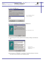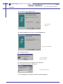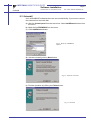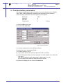
1
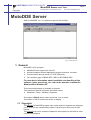
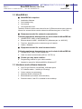
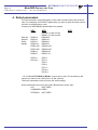
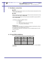
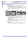
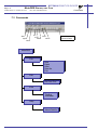
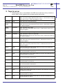
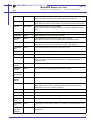
MOTOMAN
MOTOMAN XRC
USER’S MANUAL
MotoDDE version 3.xx
Upon receipt of the product and prior to initial operation, read these instructions thoroughly,
and retain for future reference.
MOTOMAN ROBOTICS EUROPE
A subsidiary of YASKAWA Electric Corporation
MANUAL NO. MRS55050
MOTOMAN ROBOTICS EUROPE
Revision
000115
Manual updated from old manual (ver. 2.0). New items included.
Also valid for MOTOMAN XRC. PRELIMINARY ISSUE !
021024
Minor corrections.
MOTOMAN ROBOTICS EUROPE
MotoDDE Server, ver. 3.xx
Created: 00-01-14 Revised: 02-10-24
Page: I
Doc. name: Mrs55050TOC.fm
1. General ................................................................. 1
Copyright
MotoDDE-kit
❏
MotoDDE-kit comprises
❏
Equipment needed for network communication
❏
Equipment needed for serial communication
❏
Further you may have need for:
Hardware and software demands
1
2
2
2
2
2
2
2. Software installation ............................................. 3
Installation
After installation
Uninstall
3
6
7
3. Communication parameters ................................. 9
4. Robot parameters ............................................... 10
5. Hardware connection .......................................... 11
❏
❏
❏
ERC
MRC
XRC
11
11
11
6. I/O and IRQ installation ...................................... 11
Serial connection
Network connection
12
12
7. Program structure ............................................... 13
Files
Helpprogram
Commands
13
13
14
8. Program running ................................................. 15
Start
Stop
15
15
9. Tags to server ..................................................... 16
10. Client software .................................................... 18
Application software
Client connection
18
18
11. Trouble shooting ................................................. 18
MOTOMAN ROBOTICS EUROPE
Page: II
MotoDDE Server, ver. 3.xx
Created: 00-01-14 Revised: 02-10-24
Doc. name: Mrs55050TOC.fm
MOTOMAN ROBOTICS EUROPE
MotoDDE Server, ver. 3.xx
Copyright
Created: 99-01-12 Revised: 02-10-24
Page: 1
Doc. name: Mrs55050-ch1.fm
MotoDDE Server
Valid for MotoDDE, ver. 3.xx (Motoman part No. 441129-99).
Fig.1 Main Screen
1. General
MotoDDE is a PC-program.
✔ Machine/Process supervision from PC.
✔ Interface between different application program and robot, see table.
✔ Communication through serial or TCP/IP (Ethernet).
✔ For controllers type YASNAC ERC / MRC or MOTOMAN XRC.
For more basic information about installation and handling of the
software, icons, menu bars, etc. refer to the operator’s manual for
Windows95 or Windows NT.
This manual shall always be available to operator.
This Operator’s Manual comprises information about:
✔ Installation / Setup / Handling / Operation
Text written in BOLD letters means command, icon or button.
Text written in ITALIC means text shown on display.
1.1 Copyright
The diskette for MotoDDE-program may not be copied or imparted to a third party
nor be used for any unauthorized purpose. Copies may be done only for own
backup.
This manual may not be copied or imparted to a third party nor be used for other
unauthorized purpose.
MOTOMAN ROBOTICS EUROPE
MotoDDE Server, ver. 3.xx
Page: 2
Created: 99-01-12 Revised: 02-10-24
Doc. name: Mrs55050-ch1.fm
MotoDDE-kit
1.2 MotoDDE-kit
■
✔
✔
✔
✔
MotoDDE-kit comprises
Installation diskettes
One hardware key
One manual
One registration card
The basic version includes user licence for two (2) Ethernet-clients (two systems).
Licence for serveral clients can be ordered as accessories (part. no. 441132).
■ Equipment needed for network communication
Following equipment demands but are not included in MotoDDE-kit:
✔ YASNAC ERC / MRC or MOTOMAN XRC.
✔ Ethernet board for MRC, JANCD-MIF06, (Motoman part. no. 9050107).
✔ Tranciver, depending on the customers type of network.
✔ Cables / Adaptors
■ Equipment needed for serial communication
Following equipment demands but are not included in MotoDDE-kit:
✔ YASNAC ERC / MRC or MOTOMAN XRC.
✔ Cable for serial communication (MS no. 341779-xx).
■ Further you may have need for:
✔ Programming manual for your robot controller.
✔ Operator’s manual for Windows95/98 or Windows NT.
1.3 Hardware and software demands
✔
✔
✔
✔
✔
✔
One PC type Pentium, 32 Mb RAM, 2 Mb disk space.
3,5”-diskette station, 1,44 Mb (or CD-setup)
Colour monitor (not necessary).
Windows 95/98 or Windows NT.
Ethernetboard (at network communication).
Protective hood, if the PC is installed in the workshop.
MOTOMAN ROBOTICS EUROPE
Software installation
Installation
Created: 96-01-31 Revised: 02-10-24
Page: 3
Doc. name: Software-installation.fm
2. Software installation
Note!
This chapter shows a general installation phase of any software. In this example
the software FDDWIN is installed. Select the right software by choosing the
appropriate software name.
2.1 Installation
There are three ways to start installation of this software, all will give the same
result. The most common way is described below.
a) Put the first diskette named #1 in the disk-drive.
b) Click on the Start button on the menu-bar.
c) Choose Run from the menu.
d) Browse to drive A:\
e) Choose the file named SETUP.EXE
f) Click OK.
Fig.2 Choose installation file
g) Choose OK and the installation guide will start.
h) You can quit the installation att any time by clicking the Cancel-button and
then confirm by Yes-button.
Fig.3 You can cancel
installation at any time
i) Mark the language you want to use during installation. Note! This will not influence the language you use in FDDWIN32 later.
MOTOMAN ROBOTICS EUROPE
Software installation
Page: 4
Created: 96-01-31 Revised: 02-10-24
Installation
Doc. name: Software-installation.fm
j) Click on the OK-button.
Fig.4 Language selection
during installation
k) Pass this information screen by clicking the Next-button.
Fig.5 Information screen
l) Read through the license agreement and accept by clicking on the Next-button.
Fig.6 License
agreement. Accept by
clicking Next.
m) Set directory for FDDWIN32. It’s advisable to install the software in the directory which is set as default by the installation guide.
MOTOMAN ROBOTICS EUROPE
Software installation
Installation
Created: 96-01-31 Revised: 02-10-24
Page: 5
Doc. name: Software-installation.fm
n) Accept by clicking Next-button.
Fig.7 Choose
directory
o) Accept installation process by clicking Next-button.
Fig.8 Start installation
p) Installation starts.
Fig.9 Installation
progress counter
q) After some time you are told to enter disk #2/2.
r) Insert disk and click on OK-button.
Fig.10 Insert disk #2
s) The installation is finished and the last screen appears.
MOTOMAN ROBOTICS EUROPE
Software installation
Page: 6
Created: 96-01-31 Revised: 02-10-24
After installation
Doc. name: Software-installation.fm
t) Accept installation by clicking the Finish-button.
Fig.11 Installation
complete
u) Before it is possible to run the software, the hardware key must be installed on
the parallel port.
2.2 After installation
After installation, fill in and return the registration card to Motoman
Robotics Europe AB.
During installation the main directory is automatically created and all necessary
files are installed in the specified drive.
In the end of the setup a program group (MOTOMAN) and a icon is created. To
start FDD for Windows just double-click on the Start Menu.
If you want to create a shortcut to FDDWIN32, see Windows manual for further
information
MOTOMAN ROBOTICS EUROPE
Software installation
Uninstall
Page: 7
Created: 96-01-31 Revised: 02-10-24
Doc. name: Software-installation.fm
2.3 Uninstall
As in all WIN95/NT softwares there are an uninstall facility if you want to remove
the software from the hard disk.
a) Start the Control panel from the start menu. Select Add/Remove button from
the menu.
b) Mark the line FDDWIN32 from the menu.
c) Click Add/Remove button.
Fig.12 Mark the FDDWIN32
software
d) Activate uninstall guide by Next-button.
Fig.13 Automatic uninstall
e) End the operation by clicking the Finish-button.
Fig.14 Uninstall
MOTOMAN ROBOTICS EUROPE
Page: 8
Created: 96-01-31 Revised: 02-10-24
Software installation
Doc. name: Software-installation.fm
Uninstall
MOTOMAN ROBOTICS EUROPE
MotoDDE Server, ver. 3.xx
Created: 99-01-12 Revised: 02-10-24
Page: 9
Doc. name: Mrs55050-ch3.fm
3. Communication parameters
The communication protocol is very special, (for more information see YASNAC
ERC / MRC or MOTOMAN XRC computer communication User’s manual.)
Communication parameters in the PC shall be set as follows:
Baud rate
4800
Data bits
8
Stop bits
1
Parity check
0
(None)
a) Click on Edit in the menu.
b) Click on Set Com Port.
Fig.15 Port setting menu
c) Choose parameters for the robot (see above)
d) Name the robot, for example Robot 1
e) Choose Serial or TCP/IP.
f) If you select TCP/IP the robots IP-address has to be entered.
g) In the field Update data you tell the program how often update from robot shall
take place.
The value is written in time; miliseconds. (1000 milisec = 1 sec).
In this example the update will take place every second.
h) When the settings are ok, click on the OK-button.
MOTOMAN ROBOTICS EUROPE
Page: 10
MotoDDE Server, ver. 3.xx
Created: 99-01-12 Revised: 02-10-24
Doc. name: Mrs55050-ch3.fm
4. Robot parameters
For communication some parameters in the robot controller has to be set as follows. For changing of SD and FD parameters you have to open the robot controller which is protected by a code.
Contact your MOTOMAN-representative for support.
Data bit
Stop bit
Parity
Speed
ERC
MRC
RS00=8
RS01=0
RS02=0
RS03=64
RS06=100
RS07=255
RS08=4
RS09=5
RS000= (*) Std. port #1
RS001= (*) Std. port #2
RS030=8
RS031=0
RS032=0
RS033=6
RS034=100
RS035=255
RS036=30
RS037=10
SD78=1
SD110=1
XRC
FD0=1
FD1=1
FD3=1
FD5=1
FD7=1
FD14=1
FD15=1
*) To run MotoDDE RS000 or RS001 must be set in value ”2” according to the
contact you want to use. (Std. port #1 or Std. port #2).
These two parameters must not have the same setting!
Some parameters have to be set under ”Maintenance mode” also.
I/O=
NOT USED
COMMAND= USED
PP/PBOX= NOT USED
MOTOMAN ROBOTICS EUROPE
MotoDDE Server, ver. 3.xx
Created: 99-01-12 Revised: 02-10-24
Page: 11
Doc. name: Mrs55050-ch3.fm
5. Hardware connection
■ ERC
Connect the 25-pole cable connector to the 25-pole socket underneath the lid at
the front of the CRT-panel.
■ MRC
Connect the 25-pole cable connector to the 25-pole socket underneath the lid at
the front of the door-panel = Std. port #1.
Connect the 9-pole adaptor to the 9-pole socket inside MRC located at MCP01board = Std. port #2.
(*) Settings for parameter RS000 / RS001:
0 = Not used
1 = Printer
2 = Data transmission protocol (PC as host)
3 = FC1 protocol (FDD software)
Hardware key
To be able to run the program it is necessary to apply the hardware key. Mount
the hardware key on the parallel port of the PC.
For Windows NT application a parallellport must be installed/created, see Windows NT manual.
■ XRC
........
6. I/O and IRQ installation
For connection following settings are recommended in the PC.
Port
I/O
IRQ
Com1
03F8
4
Com2
02F8
3
Com3
03E8
5
Com4
02E8
9
Settings of I/O and IRQ are made of the software in Windows, choose Control
panel/ Port.
MOTOMAN ROBOTICS EUROPE
MotoDDE Server, ver. 3.xx
Page: 12
Created: 99-01-12 Revised: 02-10-24
Serial connection
Doc. name: Mrs55050-ch3.fm
6.1 Serial connection
Connection between the PC and the robot controller through serial RS232
interface.
Maximum cable length are 15 meters for every robot controller. It’s
possible to use short distance modem if the distance is longer.
Com1 and Com3 are 9-pole plug.
Com2 and Com4 are 25-pole plug.
Cable layout, see figure.
(Ground/shield)
1
2
3
1
2
3
4
5
6
7
8
13
20
25
4
5
6
1
2
3
4
5
6
7
8
9
7
8
9
20
Cabel
ERC / MRC / XRC
25
PC 25-pole
Adaptor
PC 9-pole
Fig.16 Cabel and adaptor
6.2 Network connection
For information about network connection, see separate manual for Ethernet-connection (only MRC).
MOTOMAN ROBOTICS EUROPE
MotoDDE Server, ver. 3.xx
Files
Created: 99-01-12 Revised: 02-10-24
Page: 13
Doc. name: Mrs55050-ch3.fm
7. Program structure
DdeSvr is a DDE-server ( Dynamic Data Exchange ) software. The
program work as a link between a client and ERC/MRC/XRC. DdeSvr control the
status of the tags which the user set up in the client program
continously. If any of the tags are changed the application software is notified and
data is updated. Tags are functions and variables in ERC/MRC/XRC which can
be red to, written to or both from external units.
7.1 Files
PC
Application
DdeSvr
e.g. InTouch
Main file
MOTOCOM32
.dll
Robot
controller
Fig.17 Data flow
MotoDDE consist of one main file communicating with the application software
and controlling the functions. The main file is
written as a Windows based program. Therefore, the functions and the menus are
the same as for Windows.
MotoDDE uses the colours set up for Windows, which can be set under the Windows Control panel.
MotoDDE also contains a Dll-file whos supervice the communication between the
PC and the robot controller, type ERC/MRC/XRC.
7.2 Helpprogram
When MotoDDE runs via Ethernet a help program called: High Speed Link Server
is used. This program was installed at the same time as MotoDDE.
MOTOMAN ROBOTICS EUROPE
MotoDDE Server, ver. 3.xx
Page: 14
Created: 99-01-12 Revised: 02-10-24
Commands
Doc. name: Mrs55050-ch3.fm
7.3 Commands
New
Open
Save
Cut
Print
Copy
About
Paste
MotoDDE
File
New
Open
Save
Save As
Exit
Edit
Set Com Port
View
Toolbar
Statusbar
Help
About DdeSvr
Start / Stop
communication
MOTOMAN ROBOTICS EUROPE
MotoDDE Server, ver. 3.xx
Start
Created: 99-01-12 Revised: 02-10-24
Page: 15
Doc. name: Mrs55050-ch3.fm
8. Program running
The MotoDDE-program is activated and runs in the background. MotoDDE is
used like a “translator” between the application program and the MOTOMANrobot.
8.1 Start
MotoDDE activates and runs by the application program.
a) Start the program by double-click on the icon, the start menu is
shown, (Fig. 1).
b) Click on Open and inform which file with settings of file transfer you are going
to use, for more information about the file system, see
Windows manual.
Fig.18 Choose file
c) Set the robot in REMOTE-mode.
d) Start High Speed Link Server (only at network!).
e) Minimize HSLS (only at network!).
f) Start the communication by double-click on the Z-button.
g) Now MotoDDE can be minimized.
h) Start the application program, e.g. InTouch.
8.2 Stop
a) Stop the communication by clicking on the Z-button again.
b) Finish HSLS.
c) Finish MotoDDE.
MOTOMAN ROBOTICS EUROPE
MotoDDE Server, ver. 3.xx
Page: 16
Created: 99-01-12 Revised: 02-10-24
Doc. name: Mrs55050-ch3.fm
Stop
9. Tags to server
Following tags, items, are available in the DDE-server with name if any are able to
read or write or both, together with comments about the function.
SERVO
Read/Write
Read: Indicates whether voltage is supplied for the servo's.
Write: Turns servovoltage ON when item is set to 1. Turns off servo voltage
when item is set to 0. Write only applies for XRC.
JOBNAME
Read
Read: Get name of the selected job.
PLAYMODE
Read/Write
Read: Indicates if the robot is in Play mode.
Write: Sets robot in Play mode when item is set to 1. When item is set to 0
no change is applied.
MODETEACH
Read/Write
Read: Indicates Teach mode.
Write: Sets Teach mode when item is set to 1. When item is set to 0 no
change is applied.
ALARM
Read
Read: Indicates if any alarm is given in robot.
CYCLELO
OP
Read/Write
Read: Indicates if robot is in "Cycle loop".
Write: Sets robot in "Cycle loop" when item is set to1. When item is set to 0
no change is applied.
CYCLEONE
Read/Write
Read: Indicates if robot is in "One cycle".
Write: Sets "One cycle" when item is set to 1. When item is set to 0 no
change is applied.
CYCLESTE
P
Read/Write
Read: Indicates if robot is in "Cycle step".
Write: Sets "Cycle step" when item is set to 1. When item is set to 0 no
change is applied.
IO0xxx
Read
Robot universal input. Read: Reads status for I/O bits in the 0000 serie.
Xxx must be between 010 and 167.
IO1xxx
Read
Robot universal output. Read: Reads status for I/O bits in the 1000 serie.
Xxx must be between 010 and 167.
IO2xxx
Read
Robot external input. Read: Reads status for I/O bits in the 2000 serie. Xxx
must be between 010 and 187.
IO3xxx
Read
Robot external output. Read: Reads status for I/O bits in the 3000 serie.
Xxx must be between 010 and 187.
IO4xxx
Read
Robot specific input. Read: Reads status for I/O bits in the 4000 serie. Xxx
must be between 010 and 167.
IO5xxx
Read
Robot specific output. Read: Reads status for I/O bits in the 5000 serie.
Xxx must be between 010 and 247.
IO6xxx
Timer/Counter. Present status: neither Read nor Write. Xxx must be
between 010 and 047.
IO7xxx
Read
Auxilary relay. Read: Reads status for I/O bits in the 7000 serie. Xxx must
be between 010 and 327.
IO80xx
Read
Control status signals. Read: Reads status for I/O bits in the 8000 serie. Xx
must be between 10 and 87.
IO82xx
Read
Psuedo input signals. Read: Reads status for I/O bits in the 8200 serie. Xx
must be between 10 and 47.
MOTOMAN ROBOTICS EUROPE
MotoDDE Server, ver. 3.xx
Stop
Created: 99-01-12 Revised: 02-10-24
Page: 17
Doc. name: Mrs55050-ch3.fm
IO9xxx
Read/Write
Network input. Read: Reads status for I/O bits in the 9000 serie. Write:
Sets new status for I/O bits. Xxx must be between 010 and 167.
BYTExxx
Read/Write
Read: Reads value on byte variable.
Write: Sets new value on byte variable. Xxx must be between 000 and 999.
INTxxx
Read/Write
Read: Reads value on integer variable.
Write: Sets new value on integer variable. Xxx must be between 000 and
999.
JOBLINE
Read
Read: Indicates current line in the active job.
JOBSTEP
Read
Read: Indicates current step in the active job.
PULSES
xRySz
Read
Read: Reads the pulsenumber for a axis. Axis x can be
S,L,U,R,B,T,7,8,9,10,11,12. Y is robotnumber, Z is stationsnumber.
PULSESx
Read
Read: Reads the pulsenumber for a axis. Axis x can be
S,L,U,R,B,T,7,8,9,10,11,12. This item is for robot 1 and station 1.
FRAMEBASEx
Read
Read: Pulsenumber for för a axis. X can be X,Y or Z.
FRAMETx
Read
Read: Reads the"wrist angle" of the robot in degrees. X can be X,Y or Z.
FRAMEx
Read
Read: Reads the robotposition in XYZ coordinates. X can be X,Y or Z.
HOLD
Read/Write
Read: Indicates "Panel hold" in the robot.
Write: Sets robot to "hold" when item is set to 1. When item is set to 0
"hold" is exited.
PANELHOLD
Read
Read: Indicates "Panel hold" in robot.
PENDANTHOLD
Read
Read: Indicates "Programming pendant hold" in robot.
EXTERNALHOLD
Read
Read: Indicates "External hold" in robot.
COMMANDHOLD
Read
Read: Indicates "Command hold" in robot.
START
Read/Write
Read: 1 indicates that the robot is running.
Write: When item is set to 1 the selected job starts from the beginning.
When item is set to 0 no change is applied.
CONTINUE
Write
Write: The robot continues from the current jobline when item is set to 1
PLAYSTOP
Read
Read: Indicates if the robot is stopped.
PLAYBACK
Read
Read: Indicates if the robot is running with normal velocity.
PLAYSPECIAL
Read
Read : Indicates if the robot is running with safe velocity.
ALARMDATAx
Read
Read: Up to 4 alarm codes. Integer. 0 if no alarm. X can be between 0 and
3.
COMMUNICATION
ERROR
Read
Read: 1 indicates communication-error between the robot and the PC ,
otherwise 0.
MOTOMAN ROBOTICS EUROPE
Page: 18
MotoDDE Server, ver. 3.xx
Created: 99-01-12 Revised: 02-10-24
Application software
Doc. name: Mrs55050-ch3.fm
10. Client software
10.1 Application software
Following application software can be used together with MotoDDE:
Brand*
InTouch
FactoryLink
Citect
Fix
Manufacturer
Wonderware Inc.
USDATA Corporation
Ci Technologies Pty ltd
Intellution Inc.
*) Product name are registered trademarks by the manufacturer.
10.2 Client connection
The DDE server has applicationname"MotoDde"
DDE client topic shall be set to the same name as DDE server robot name. (e.g.
Robot 1).
11. Trouble shooting
Following error messages can appear in MotoDDE.
Communication fail
If these messages appears;
✔ Check the communication and network.
✔ Check the parameter setting in MotoDDE and in ERC/MRC/XRC.
✔ Check that the robot is set in REMOTE-mode.
Notes
Headquarters:
Sweden
Group companies:
Finland
France
Germany
Germany
Great Britain
Italy
Netherlands
Portugal
Slovenia
Spain
Sweden
Distributors:
Czech Republic
Greece
Hungary
Israel
Norway
South Africa
Switzerland
MOTOMAN Robotics Europe AB
Box 504, SE-385 25 Torsås, Sweden
Tel: +46-486-48800, +46-486-41410
MOTOMAN Robotics Finland OY
Messinkikatu 2, FI-20380 Turku, Finland
Tel: +358-403000600, Fax: +358-403000660
MOTOMAN Robotics SARL
Rue Nungesser et Coli, D2A Nantes-Atlantique, F-44860 Saint-Aignan-de-Grand-Lieu, France
Tel: +33-2-40131919, Fax: +33-40754147
MOTOMAN Robotec GmbH
Kammerfeldstraße 1, DE-85391 Allershausen, Germany
Tel: +49-8166-90-0, Fax: +49-8166-90-103
MOTOMAN Robotec GmbH
Im Katzenforst 2, DE-61476 Kronberg/Taunus, Germany
Tel: +49-6173-60-77-30, Fax: +49-6173-60-77-39
MOTOMAN Robotics UK (Ltd)
Johnson Park, Wildmere Road, Banbury, Oxon OX16 3JU, Great Britain
Tel: +44-1295-272755, Fax: +44-1295-267127
MOTOMAN Robotics Italia SRL
Via Emilia 1420/16, IT-41100 Modena, Italy
Tel: +39-059-280496, Fax: +39-059-280602
MOTOMAN benelux B.V
Zinkstraat 70, NL-4823 AC Breda, Netherlands
Tel: +31-76-5424278, Fax: +31-76-5429246
MOTOMAN Robotics Iberica S.L. - Sucursal em Portugal
Z. Ind. Aveiro Sul, Lote 21, N. S. Fátima, PT-3810 Aveiro, Portugal
Tel: +351-234 943 900, Fax: +351-234 943 108
RISTRO d.o.o.
Lepovce 23, SI-1310 Ribnica, Slovenia
Tel: +386-61-861113, Fax: +386-61-861227
MOTOMAN Robotics Iberica S.L.
Avenida Marina 56, Parcela 90, ES-08830 St. Boi de Llobregat (Barcelona), Spain
Tel: +34-93-6303478, Fax: +34-93-6543459
MECATRON Robotic Systems AB
Box 4004, SE-390 04 Kalmar, Sweden
Tel: +46-480-444600, Fax: +46-480-444699
MGM Spol s.r.o.
Trebízského 1870, CZ-39002 Tábor, Czech Republic
Tel: +420-361-254571, Fax: +420-361-256038
Kouvalias Industrial Robots
25, El. Venizelou Ave., GR-17671 Kallithea, Greece
Tel: +30-1-9589243-6, Fax: +30-1-9567289
REHM Hegesztéstechnika Kft.
Tápiószele, Jászberényi út 4., H-2766, Hungary
Tel: +36-30-9510065, Fax: +36-1-2562012
KNT Engineering Ltd.
9 Hapalmach Street, IL-Kfar Azar 55905, Israel
Tel: +972-3 9231944, Fax: +972-3 9231933
ROBIA ASA
Industriveien 1, NO-3300 Hokksund, Norway
Tel: +47-32252820, Fax: +47-32252840
Robotic Systems S.A. PTY Ltd
4 Friesland Drive, Longmeadow Business Estate-South Modderfontein 1610, Johannesburg, South Africa
Tel: +27-11-4943604, Fax: +27-11-4942320
Messer SAG
Langweisenstrasse 12, CH-8108 Dällikon, Switzerland
Tel: +41-18471717, Fax: +41-18442432
a subsidiary of YASKAWA Electric Corporation