1
ER12
SERVICEMANUAL
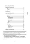
CONTENTS
Section
Title
Page
1. SPECIFICATIONS. . . . . . . . . . . . . . . . . . . . . . . . . . . . . . . . . . . . . . . . . . . . . . . 1
2. PERFORMANCE . . . . . . . . . . . . . . . . . . . . . . . . . . . . . . . . . . . . . . . . . . . . . . . 2
3. FEATURES . . . . . . . . . . . . . . . . . . . . . . . . . . . . . . . . . . . . . . . . . . . . . . . . . . . . 4
4. GENERAL DESCRIPTION OF ENGINE COMPONENTS . . . . . . . . . . . . . . . . 5
5. DISASSEMBLY AND REASSEMBLY . . . . . . . . . . . . . . . . . . . . . . . . . . . . . . . 12
5-1 PREPARATIONS AND PRECAUTIONS . . . . . . . . . . . . . . . . . . . . . . . . . . . 12
5-2 SPECIAL TOOLS . . . . . . . . . . . . . . . . . . . . . . . . . . . . . . . . . . . . . . . . . . . . . 12
5-3 DISASSEMBLY PROCEDURE . . . . . . . . . . . . . . . . . . . . . . . . . . . . . . . . . . 13
5-4 REASSEMBLY PROCEDURE . . . . . . . . . . . . . . . . . . . . . . . . . . . . . . . . . . . 27
6. ENGINE OIL . . . . . . . . . . . . . . . . . . . . . . . . . . . . . . . . . . . . . . . . . . . . . . . . . . . 43
7. LUBRICATION SYSTEM . . . . . . . . . . . . . . . . . . . . . . . . . . . . . . . . . . . . . . . . . 44
8. MAGNETO . . . . . . . . . . . . . . . . . . . . . . . . . . . . . . . . . . . . . . . . . . . . . . . . . . . . 47
9. WIRING DIAGRAM . . . . . . . . . . . . . . . . . . . . . . . . . . . . . . . . . . . . . . . . . . . . . . 48
10. AUTOMATIC DECOMPRESSION SYSTEM. . . . . . . . . . . . . . . . . . . . . . . . . . 49
11. CARBURETOR . . . . . . . . . . . . . . . . . . . . . . . . . . . . . . . . . . . . . . . . . . . . . . . . 50
12. RECOIL STARTER . . . . . . . . . . . . . . . . . . . . . . . . . . . . . . . . . . . . . . . . . . . . . 58
13. INSTALLATION . . . . . . . . . . . . . . . . . . . . . . . . . . . . . . . . . . . . . . . . . . . . . . . . 63
14.TROUBLESHOOTING . . . . . . . . . . . . . . . . . . . . . . . . . . . . . . . . . . . . . . . . . . . 65
15. STANDARD REPAIR TABLES . . . . . . . . . . . . . . . . . . . . . . . . . . . . . . . . . . . . 68
15-1 STANDARD DIMENSIONS AND LIMITS OF USE . . . . . . . . . . . . . . . . . . 68
15-2 SERVICE DATA (The following are only for your reference.). . . . . . . . . . . 73
15-3 TIGHTENING TORQUE. . . . . . . . . . . . . . . . . . . . . . . . . . . . . . . . . . . . . . . 74
15-4 AIR GAP AND CLEARANCE . . . . . . . . . . . . . . . . . . . . . . . . . . . . . . . . . . . 74
16.MAINTENANCE AND STORAGE . . . . . . . . . . . . . . . . . . . . . . . . . . . . . . . . . . 75
1. SPECIFICATIONS
Model
ER12
Air-Cooled, 4-Cycle, Single-Cylinder,
Horizontal P.T.O. Shaft, OHC Gasoline Engine
Type
Bore × Stroke
mm (in.)
Piston Displacement
ml (cu.in.)
60 × 43 (2.36 × 1.69)
121 (7.38)
Compression Ratio
9.6
Maximum Output
kW(HP)/r.p.m.
2.6(3.5)/3600
Maximum Torque
N m / r.p.m.
(kgf m / r.p.m.)
(ft lb. / r.p.m.)
7.3/2400
(0.74/2400)
(5.38/2400)
Direction of Rotation
Counterclockwise as viewed from the P.T.O. shaft side
Valve Arrangement
Overhead cam system
Cooling System
Forced air cooling system
Lubrication System
Trochoid Pump, Forced and Splash lubrication system
Automotive detergent oil - SAE; #20, #30 or 10W-30
API service class; SE or higher (SG, SH or SJ is recommended)
Lubricant
Capacity of Lubricant
L (U.S. gal.)
0.35 (0.092)
Carburetor
Horizontal draft, Float type or Diaphragm type
Fuel
Automobile unleaded gasoline
Fuel Supply System
Gravity type
Spark Plug
NGK CR5HSB
Starting System
Recoil starter
Governor
Centrifugal flyweight type
Air Cleaner system
Semi wet type
Dry Weight
kg (lb.)
Dimensions (L x W x H)
mm (in.)
9.9 (21.78)
264 x 288 x 334 (10.39 x 11.34 x 13.15) : Float type Caburetor
264 x 288 x 336 (10.39 x 11.34 x 13.23) : Diaphragm type Caburetor
*Specifications are subject to change without notice.
- 1-
2. PERFORMANCE
2-1 MAXIMUM OUTPUT
The Maximum output is the output of an engine with its throttle valve fully opened and considering that all the
moving parts are properly broken in.
A new engine may not produce full maximum output while its moving parts are still not broken-in.
NOTE :
Power curves shown in the following charts are made in conformity with SAE internal combustion engine
standard test code J1349.
2-2 CONTINUOUS RATED OUTPUT
The continuous rated output is the output of an engine at optimum governed speed which is most favorable
from the view point of engin’s life and fuel consumption.
When the engine is installed on a certain equipment, it is recommended that the continuous output required
from the equipment to be kept below this continuous rated output.
2-3 MAXIMUM TORQUE
The maximum torque is the torque at the output shaft when the engine is producing maximum output at a
specific r.p.m..
- 2-
2-4. PERFORMANCE CURVES
8.0
M A X IM UM
TORQUE
[HP]
4.0
kW
3.0
M A X IM UM
HORS EPOWER
3.0
2.0
OUTPUT
RECOMMENDED
HORSEPOWER
RANGE
2.0
1.0
1.0
0
0
2000
3000
REVOLUTION
- 3-
4000
r.p.m.
[kgf・m]
0.9
0.8
7.0
0.7
6.0
0.6
TORQUE
N・m
3. FEATURES
3-1. DEVELOPED EXCLUSIVELY FOR RAMMER
The new ER12 has been developed exclusively for rammer, which especially requires the engine for high
durability, high power output and superb mountability among many construction machineries.
3-2. LIGHTWEIGHT AND COMPACT DESIGN
ER12 has realized lightweight and compact design, while achieving high power output of 2.6kW (engine
displacement 120cc) that enables to widely fulfill the operating weight of 60 to 80kg-class rammers, the
lightest-in-class* weight of 9.9kg, and the smallest-in-class* on the length and width.
3-3. DESIGNED TO OFFER SUPERIOR MOUNTABILITY
ER12 has been designed to offer superior mountability, which is valued for rammer engine, by the optimal
center of gravity for right-and-Ieft balance.
3-4. USER'S SAFETY AS WELL AS USER FRIENDLINESS
ER12 offers several new functions as standard equipment, which has been required to rammer engine for
user's safety as well as user friendliness, such as oil sensor that monitors the oil level not only at starting-up
but also during operation, and automatic shutoff device that stops engine when the rammer rolls over or has
no operation with idling.
3-5. EASE OF MAINTENANCE AND ECONOMICAL EFFICIENCY
ER12 has beeh designed in consideration of ease of maintenance and economical efficiency, such as
adopting solid crank case or the newly developed resinous dust-proof air cleaner for realizing ease of
maintenance, realizing longer operational hours without oil-refilling.
* FHI researches
- 4-
4. GENERAL DESCRIPTION OF ENGINE COMPONENTS
4-1 CYLINDER AND CRANKCASE
The cylinder and crankcase are aluminum die-casting
as a single piece. A special cast iron cylinder liner is
molded into the aluminum die-casting.
The crankcase has a mounting surface on the output
shaft side to which the main bearing cover is attached.
And the lib is made for the crankcase room center
cum oil shelter plate, that improvement breather
function and strength up.
And inside of the crankcase has large rib for oil shelter
which to inprove the breather function and stiffness.
4-2 MAIN BEARING COVER
The main bearing cover is an aluminum die-casting
with heavy-duty structure to endure to install on
rammers, which is mounted on the output shaft side of
the crankcase. By removing the main bearing cover,
the inside of the engine can be inspected with ease.
Pilots and bosses are machined into the cover for
direct mounting of the engine onto rammers.
And it have suction pipe, oil pump, oil filter and oil
pressure switch.
4-3 CRANKSHAFT
The crankshaft is forged carbon steel, and the crank
pin is high-frequency inductionhardened.
The crank pulley used to drive the timing belt and the
gear used to drive the governor gear are pressed into
the output end of the shaft.
The connecting rod is a specially heat-treated
aluminum alloy die-casting. Its large and small ends
function as bearings. The piston is an aluminum alloy
casting with grooves for mounting one compression
ring and one oil ring.
- 5-
JCC
4-4 CONNECTING ROD AND PISTON
4-5 PISTON RINGS
The piston rings are made of special cast iron. The profile of the top ring is a tapered face.
The oil ring is designed for better sealing and less oil consumption, in combination with 3 pieces.
1
1
TOP
RING
TAPER
2
OIL
RING
THREE-PIECE
CONSTRUCTION
2
4-6 CAMPULLEY
The campulley is made of special nylon. They are
constructed as a single piece. The campulley is
provided with intake and exhaust cam, and the
decompression release lever is mounted on the
sprocket shaft end side.
4-7 VALVE ARRANGEMENT
EXHAUST VALVE
This engine has a belt-driven overhead cam and
overhead valve construction, with a single cam
performing both intake and exhaust operations.
- 6-
INTAKE VALVE
4-8 CYLINDER HEAD
The cylinder head is on aluminum die-casting with a
lens-shaped combustion chamber. The intake and
exhaust ports are arranged in a cross direction to
improve combustion efficiency.
4-9 GOVERNOR SYSTEM
This engine is equipped with a centrifugal flyweight
type governor that makes it possible to operate the
engine at a constant speed, even with load
GOVERNOR
GEAR
variations. (The governor flyweights are mounted on
a governor gear.)
4-10 COOLING SYSTEM
The engine uses a forced air-cooling system in which a cooling fan on the frywheel, reduce noise and forces
cooling air into the cylinder and cylinder head.
Baffle is provided to guide the flow of cooling air.
4-11 LUBRICATION SYSTEM
Lubricant (engine oil) is sprayed onto the parts with pressure spray by the trochoid type of oil pump, and
those parts splashes to the parts necessary to be lubricated.
The trochoid pump is driven by the crankshaft. Lubricant is wholly filtered by the oil pump filter plugged in the
under of the main bearing cover.
- 7-
4-12 TIMING BELT
CAMPULLEY
Timing belt system is adopted and designed for
lubricating for the upper portion of cylinder head.
The timing belt is engaged between the campulley in
TIMING BELT
the cylinder head and the crankshaft gear.
The pulley and the gear teeth in round shape are
DRIVEPULLEY
adopted to enhance the durability and to realize low
noise level.
CRANKSHAFT
4-13 IGNITION SYSTEM
IGNITION COIL
The ignition system is a pointless flywheel magnet by
a digital control.
FLYWHEEL
The magneto consists of a flywheel and ignition coil
THICKNESS
GAUGE
with CPU (Central Processing Unit.) and CDI
(Capacitor Discharge Ignition.). The flywheel is
directly mounted on the crankshaft and the ignition
FAN
coil is directly mounted on the crankcase.
4-14 CARBURETOR
The engine is equipped with two types of horizontal
draft carburetors, one has a float controlled fuel system
and a fixed main jet, and another is diaphragm type.
The carburetors are calibrated carefully for sure
starting, good acceleration, less fuel consumption and
maximum output.
For details, refer to page 50, section “11-3 FLOAT
CARBURETOR As details of diaphragm type, refer to
page 53, section “11-4 DIAPHRAGM CARBURETOR”.
- 8-
FLOAT TYPE
DIAPHRAGM TYPE
4-15 AIR CLEANER
AIR CLEANER BASE
ELEMENT
The air-cleaner is a heavy-duty type with a dual
URETHANE FOAM
element system; the primary one is an urethane foam
(semi-wet) and secondary one is a semi wet type
element.
AIR CLEANER COVER
4-16 DECOMPRESSION SYSTEM
The automatic decompression system is mounted on
RETURN SPRING
the campulley. It opens the exhaust valve before the
ROCKER ARM
(EXHAUST VALVE SIDE)
compression top, thereby alleviating the compression
pressure and reducing the force required to pull the
recoil starter.
During engine operation, the decompression system
EXHAUST VALVE
is overpowered by centrifugal force and compression
is fully utilized to produce power.
CAMSHAFT
- 9-
4-17 SECTIONAL VIEW OF THE ENGINE
Cross sectional view – across the shaft
CYLINDER HEAD
SPARK PLUG
PISTON
PISTON RING
IGNITION COIL
PISTON PIN
RECOIL STARTER
OIL PRESSURE SWITCH
OIL PUMP
P.T.O. SHAFT
CRANKSHAFT
ADAPTER
FLYWHEEL
MAIN BEARING COVER
CRANKCASE
PLUG
SUCTION PIPE
SER No. (Stamping)
- 10 -
Cross sectional view – along the shaft
ROCKER COVER
ROCKER ARM
CAMPULLEY
INTAKE VALVE
FLOAT TYPE CARBURETOR
CARBURETOR
(DIAPHRAGM TYPE)
EXHAUST VALVE
MUFFLER
AIR CLEANER
PISTON RING
GOVERNOR LEVER
TIMING BELT
STOP SWITCH
CONNECTING ROD
SPEED CONTROL LEVER
OIL GAUGE
GOVERNOR GEAR
BREATHER COVER
SER No. (Stamping)
CRANKCASE
CRANKSHAFT
OIL DRAIN PLUG
- 11 -
5. DISASSEMBLY AND REASSEMBLY
5-1 PREPARATIONS AND PRECAUTIONS
1) When disassembling the engine, memorize the location of each part so that you can reassemble the engine
correctly. If necessary, attach identification tags with the required assembly information to the parts.
2) Store groups of parts in separate boxes. This will make reassembly easier.
3) To prevent parts from being mislaid, keep each group provisionally assembled after removing the parts
from the engine.
4) Handle the disassembled parts with the utmost care. Clean them with cleaning oil if necessary.
5) Use the correct tools in the correct way when disassembling and reassembling the engine.
5-2 SPECIAL TOOLS
Tool name
Use
Commercially available product
Flywheel puller
For pulling off the lywheel
Commercially available product
Piston ring plier
For removing and
installing piston rings
Commercially available product
Piston ring
compresser
For holding piston rings
Commercially available product
Chain wrench
For locking the lywheel
FLYWHEEL PULLER
PISTON RING PLIER
PISTON RING COMPRESSER
CHAIN WRENCH
- 12 -
5-3 DISASSEMBLY PROCEDURE
Step
Parts to remove
Drain the engine oill
1
Remarks and procedures
Fasteners
Remove a drain plug (M8 x 12mm) located on both
sides of the case.
Take care not to lose the gaskets.
12 mm spanner
* To discharge oil quickly, remove the oil gauge(M22).
2
Air cleaner
Remove breather pipe from rocker cover.
10mm box spanner
M6 nut:2pcs.
STEP 2
GASKET(INTAKE)
BREATHER PIPE
CLEANER BASE
CLEANER COVER
M6 SELF LOCK NUT : 2pcs.
ELEMENT
URETHANE FOAM
GASKET
(Rubber )
OIL GAUGE
GASKET
(Aluminum )
STEP 1
- 13 -
M8 DRAIN PLUG : 1pc.
Step
Parts to remove
Remarks and procedures
Fasteners
Muffler and Muffler cover
(1) Remove the muffler cover from the muffler and
gasket(muffler).
(2) Remove the muffler from the cylinder head.
Take care not to lose the gasket.
* Take care not to cut your hand with muffler gasket.
10mm box spanner or
spanner
13mm box spanner
M6×18mm:3pcs.
M6 nut:2pcs.
Recoil starter
Disconnect wire of stop switch first, then remove recoil
starter.
10mm box spanner
M6×20mm:2pcs.
M6×14mm:1pc.
3
4
RECOIL ASSY
MUFFLER
M6 x 14
FLANGE BOLT : 1 pc.
GASKET
(MUFFLER)
M6 SELF LOCK NUT : 2pcs.
STEP 3
M6 x 18
FLANGE BOLT : 3 pcs.
M4 SCREW : 2 pcs.
Do Not remove the plug.
STOP SWITCH
MUFFLER COVER
M6 x 20
FLANGE BOLT : 2 pcs.
STEP 4
- 14 -
Step
Parts to remove
Carburetor, Insulator
Remarks and procedures
Fasteners
Remove the linkage bushing from governor rod.
(1) Loosen the and remove the governor lever from
the governor shaft. There is no need to remove the
bolt.
10mm box spanner or
spanner
M6×20mm:1pc.
M6 Nut:1pc.
(2) Remove the governor spring.
5
(3) Remove the governor rod and the rod spring from
the carburetor.
Remove the carburetor from the cylinder head.
Remove the insulator.
GASKET
(INSULATOR)
BLACK
INSULATOR
GASKET
(CARBURETOR)
BROWN
ROD SPRING
LINKAGE BUSHING
CARBURETOR
(FLOAT TYPE)
CYLINDER HEAD
GOVERNOR ROD
STEP 5
GOVERNOR LEVER
GOVERNOR
SPRING
A
CYLINDER HEAD
GASKET
(INSULATOR)
BLACK
BOLT
NUT
INSULATOR 2
GASKET
STEP 5
(CARBURETOR)
BLACK
CARBURETOR
(DIAPHRAGM TYPE)
DETAIL A
GASKET
(CARBURETOR)
BROWN
SELF LOCK NUT
INSULATOR 1
GASKET
(INSULATOR)
BLACK
A
INTAKE PIPE
- 15 -
Step
6
Parts to remove
Speed control lever and
Base plate
Remarks and procedures
Fasteners
Remove the speed control lever and base plate from
the crankcase. (If necessary)
STEP 6
10mm box spanner
M6×10mm:2pcs.
14mm box spanner
Pivot bolt:1pc.
SET SCREW (HIGH SPEED)
NUT
BASE PLATE
SET SCREW (LOW SPEED)
SPEED CONTROL
LEVER
SWIVEL (NUT) M4 x 0.7
FRICTION WASHER
(NYLON)
PIVOT BOLT
RETURN SPRING
SPACER
M6×10 FLANGE BOLT:2pcs.
PIVOT BOLT Tightening torque : 7.0 - 9.0 N•m
(70 - 90 kgf•cm)
(5.1 - 6.5 ft•lb.)
SPEED CONTROL AY
GOVERNOR SPRING
STEP 6
M6×20 BOLT
- 16 -
GOVERNOR LEVER
M6 NUT
Step
7
8
Parts to remove
Remarks and procedures
Fasteners
Cylinder baffle
Remove the Cylinder baffle. (If necessary)
10 mm box spanner
M6 x 10 mm : 3 pcs.
Breather
Remove the breather cover and plate. (If necessary)
8 mm box spanner
M6 x 20 mm : 4 pcs.
Ignition coil
Remove the spark plug cap from the spark plug.
Disconnect wire of oil pressure switch.
Remove the ignition coil from the crankcase.
10 mm box spanner
M6 x 25 mm 2 pcs.
9
CYLINDER BAFFLE
STEP 7
M6×10
FLANGE BOLT:3pcs.
M6×20
FLANGE BOLT:4pcs.
BREATHER
PLATE
GASKET
(BREATHER PLATE)
STEP 8
Disconnect the wire
from the portion
BREATHER COVER
GASKET
(BREATHER COVER)
SPARK PLUG
SPARKPLUG
RUBBER CAP
IGNITION COIL
STEP 9
M6×20 BOLT : 2pcs.
SWITCH
(OIL PRESSURE)
- 17 -
Step
Parts to remove
Flywheel
Remarks and procedures
Fasteners
19 mm socket wrench
M14 nut : 1pc.
Remove the starting pully from the flywheel.
Fit a box wrench or a socket wrench on the flywheel nut
and loosen the nut by knocking the wrench sharply with a
hammer. (See Fig.4-a)
NOTE:
1. Do not insert screwdriver or other object between the
flywheel blades which is a synthetic resin, otherwise
the risk of damaging the blades might be occurred.
2. Knock the wrench with a hammer in a counter
clockwise direction.
10
Remove the flywheel from the crankshaft. Leave the nut
temporarily to prevent the flywheel from dropping out.
Fit the flywheel puller as shown in Figure4-b and remove
the flywheel from the crankshaft by rotating the bolt
at the center in a clockwise direction.(Knock the center bolt
with a hammer sometimes)
Flywheel puller
HAMMER
ALUMINUM BAR
Fig.4-a
STEP 10
NUT
PULLER
Fig.4-b
- SCREWDRIVER
WOODRUFF KEY
M14 FLANGE NUT : 1pc.
FLYWHEEL
- 18 -
Step
Parts to remove
Remarks and procedures
Fasteners
Spark plug
Remove the spark plug from the cylinder head.
16mm plug wrench
Rocker cover
(1) Remove the rocker cover from the cylinder head .
(2) Remove the gasket (rocker cover)
10mm box spanner
M6×14mm : 2pcs.
Rocker arm
Remove the pin (rocker arm)and the rocker arm from
the cylinder head at the compression top dead center.
(See Fig.4-c)
Pliers
11
12
13
STEP 11
SPARK PLUG
M6×20 FLANGE BOLT : 2pcs.
ROCKER COVER
STEP 12
VIEW A
GASKET
(ROCKER COVER)
ADJUSTMENT SCREW, NUT
Remove the pin the
allow direction
ROCKER ARM
(EXHAUST SIDE)
PIN(ROCKER)
Matching mark
ROCKER ARM
(INTAKE SIDE)
STEP 13
A
Cylinder head surface
Fig.4-c
- 19 -
Step
Parts to remove
Oil pump
Remarks and procedures
Remove oil pump cover o-ring outer rotor and inner
rotor.
14
MAIN BEARING COVER
STEP 14
OUTER ROTOR
OIL PUMP COVER
M6×12
FLANGE BOLT:4pcs.
INNER ROTOR
O-RING
(SYNTHETIC RUBBER)
- 20 -
Fasteners
8mm box wrench
M6×12mm:4pcs.
Step
Parts to remove
Main bearing cover
15
Remarks and procedures
Fasteners
12mm box wrench
M8×55mm:6pcs.
Remove the flange bolts of main bearing cover from
the crankcase.
Remove the main bearing cover while tapping gently
around the cover using a plastic hammer or similar
tool. (See Fig.4-d)
Be careful not to damage the oil gauge or oil seal or
not to lose the pipe knocks.
SPACER
STEP 15
CRANKCASE
M8×55
FLANGE BOLT : 6pcs.
MAIN BEARING COVER
MAIN BEARING COVER
PLASTIC HAMMER
Fig.4-d
- 21 -
Step
Parts to remove
Remarks and procedures
Fasteners
Switch (Oil pressure)
Remove the oil pressure switch. (If necessary)
24mm spanner
Plug and suction pipe
Remove the plug and suction pipe from the main
bearing cover. (If necessary)
M5×12mm:2pcs.
16
17
STEP 16
SWITCH
(OIL PRESSURE)
MAIN BEARING COVER
A
STEP 17
PLUG AY
(OIL FILTER)
SUCTION PIPE
MESH SCREEN
M14
O-RING
(SYNTHETIC RUBBER)
M5×12 SCREW : 2pcs.
PLUG AY
VIEW A
- 22 -
Step
Parts to remove
Remarks and procedures
Campulley
Fasteners
(1) Remove the retaining bolt of pin (campulley) from the
cylinder head.
(2) Remove the pin (campulley), taking care not to scratch the
O-ring.
(3) Remove the timing belt from the campulley and then take
out the campulley.
(4) Remove the timing belt from the crankshaft.
18
PIN
(CAMPULLEY)
10mm box spanner
M6×8mm:1pc.
Pliers
CYLINDER HEAD
O-RING
(SYNTHETIC RUBBER)
M6×8
FLANGE BOLT : 1pc.
TIMING BELT
CRANKCASE
STEP 18
CAMPULLEY
TIMING BELT
CRANKSHAFT
DRIVEPULLEY
- 23 -
Step
Parts to remove
Remarks and procedures
Cylinder head
(1) Remove the cylinder head from the crankcase.
(2) Remove the cylinder head gasket from the cylinder head.
Take care not to lose the pipe knock
Intake and exhaust
valves
(1) Remove the collet valve from the spring retainer.
(If necessary)
(2) Remove the intake valve and the exhaust valve.
19
20
Fasteners
STEP 19
12mm box spanner
M8×98mm:4pcs.
STEP 20
COLLET VALVE
STEM SEAL
(INTAKE ONLY)
M8×98
FLANGE BOLT:4pcs.
SPRING
RETAINER
VALVE SPRING
GASKET
(HEAD)
CYLINDER HEAD
KNOCK PIN
EXHAUST
VALVE
CRANKCASE
INTAKE
VALVE
- 24 -
Step
Parts to remove
Remarks and procedures
Fasteners
Connecting rod and piston
(1) Scrape off any carbon from the cylinder and the
piston head, then remove the connecting rod bolt.
(2) Remove the connecting rod cap.
(3) Rotate the crankshaft until the piston comes to its
top position. Push the connecting rod and remove
the piston from the upper part of the cylinder.
Piston and piston rings
(1) Remove the piston clips(2pcs.). Take out the
piston pin and then remove the piston from the
connecting rod small end, taking care not to
damage the connecting rod small end.
(2) Remove the piston rings from the piston by
spreading them at the gap. Take special care not
to damage the rings when doing this.
21
22
8mm box spanner
M5×25mm:2pcs.
CLIP
PISTON RING
STEP 22
PISTON
PISTON PIN
CONNECTING ROD
STEP 21
CLIP
UPPER PART OF
THE CYLINDER
CRANKSHAFT
CONNECTING
ROD CAP
CONNECTING ROD BOLT : 2pcs.
- 25 -
Step
Parts to remove
Crankshaft
Remarks and procedures
Fasteners
(1) Remove the woodruff key (for the flywheel
magneto).
(2) Remove the crankshaft from the crankcase
by tapping its magneto side end with a plastic
hammer, taking care not to damage the oil seal.
23
Plastic hammer
OIL SEAL (PRESS FITTING)
WASHER
STEP 23
E-CLIP
CRANKSHAFT
GOVERNOR SHAFT
WASHER
- 26 -
5-4 REASSEMBLY PROCEDURE
5-4-1 NOTES ON REASSEMBLY
(1) Clean the each parts carefully, taking special care with the piston, cylinder, crankshaft, connecting rod
and bearings.
(2) Scrape off any carbon deposits on the cylinder head and the piston head. Be particularly careful when
removing carbon from the piston ring grooves.
(3) Inspect the oil seals for any damage to the lip. Replace them if damaged. Apply oil to the lip before
reassembly.
(4) Replace all the gaskets with new ones.
(5) Replace the keys, pins, bolts and nuts with new ones, if necessary.
(6) Tighten nuts and bolts to the specified torque settings.
(7) When reassembling the engine, apply oil to all moving parts.
(8) Check clearances and end plays and adjust, if necessary.
(9) When mounting any major part during reassembly of the engine, rotate it with your hand to check for any
jamming or abnormal noise.
5-4-2 ASSEMBLY STEPS AND PRECAUTIONS
(1) CRANKSHAFT
(a) Wrap the key-way portion of the crankshaft with
polyvinyl tape and insert the crankshaft into the
CRANKSHAFT
crankcase, taking care not to damage the oil
seal lip.
(b) Insert the woodruff key (for the flywheel magneto).
NOTE: Do not insert the woodruff key before
inserting the crankshaft into the
POLYVINYL TAPE
crankcase.
- 27 -
(2) PISTON AND PISTON RINGS
OPEN ENDS OF PISTON RING
(a) Install each piston ring in the correct groove of
the piston by widening it enough to slide it over
the piston.
NOTE: Be careful not to twist the rings too
much, as they may be damaged. Install
the oil ring first, followed by the top ring.
When installing the piston ring, make
sure that the "R" mark is face up.
1
1
TOP
RING
TAPER
2
OIL
RING
THREE-PIECE
CONSTRUCTION
2
MARK “R”
- 28 -
(3) PISTON AND CONNECTING ROD
The piston is attached to the connecting rod by
the piston pin.
When assembling the piston and connecting
rod, make sure to align the mark on the piston
When assembling
the piston and
connecting rod,
make sure to align
the mark on the
piston head with the
“JCC”mark on the
connecting rod.
NOTE 1: Before assembling the connecting rod,
JCC
head with the ‘JCC’ mark on the connecting rod.
apply oil to its small end.
NOTE 2: Be sure to insert the clips in the two
ends of the piston pin and check the
clips for any play.
(4) CONNECTING ROD
(a)Installthepistonandconnectingrodassembly
PISTON RING GUIDE
AND PISTON RING
intothecylinderbyholdingthepistonrings
withtheringguide,withthe
JCC
markon
theconnectingrodontheflywheelside.(Ifyou
donothavearingguide,holdthepistonrings
“JCC” MARK
JCC
withthefingersandtaptheupperpartofthe
pistonwithapieceofwood.)
NOTE1:Applyoiltothepistonrings,thelarge
endoftheconnectingrodand
FLYWHEEL SIDE
cylinderbeforeinstallingthe
connectingrodintothecylinder.
NOTE2:Thepistonringgapsshouldbe
positionedaroundthepistonat
P.T.O SHAFT SIDE
180-degreeintervals.
OIL RING
180°
TOP RING
- 29 -
FLYWHEEL SIDE
("JCC" MARK SIDE)
(b) Rotate the crankshaft down to the bottom dead
center and lightly tap the piston head until the
large end of the connecting rod touches the
crank pin.
(c) To mount the connecting rod, line up the matching
ALIGNMENT
MARKS
marks and fit the clinch portions firmly together.
M5×25mm Connecting rod bolt : 2pcs.
(8mm box wrench)
Tightening torque
6.0 - 8.0 N m
(60 - 80 kgf cm)
(4.3 - 5.8 ft lb.)
(d) Check for free movement of the connecting rod
by turning the crankshaft slowly.
Make sure press fitting to contact exactly
between stem seal and Cylinder head.
STEM SEAL
CYLINDER
HEAD
(5) INTAKE AND EXHAUST VALVES
Takethefollowingpointsintoaccountwhen
mountingtheintakeandexhaustvalvesonthe
VALVE GUIDE
cylinderhead.
NOTE1:Replacethevalvewithanewoneif
COLLET VALVE
itshowssignsofwear.
SPRING
RETAINER
NOTE2:Carefullyscrapeoffanycarbon
depositsonthecombustionchamber.
STEM SEAL
(INTAKE ONLY)
VALVE SPRING
Applyoiltothevalvestemsbefore
mountingtheintakeandexhaust
valves.Insertthevalvesinthe
cylinderheadandplaceitonalevel
CYLINDER
HEAD
workbench.Next,mountthevalve
springs,thespringretainersand
colletvalves.(Mountthestemseal
Apply oil
ontheintakevalveguide.)
Apply oil
EXHAUST VALVE
INTAKE VALVE
- 30 -
(6) CYLINDER HEAD
(a) Inspect and repair any scratches on mounting surface and replace head gasket to new one before installing.
(b) Insert the pipe knocks between crankcase and cylinder head.
Install cylinder head onto cylinder with new head gasket.
Apply oil to the screw thread.
Tighten four flange bolts evenly in three steps by the following tightening torque:
Cylinder head M8×98mm bolt : 4pcs.
Tightening torque
1 st step
2 st step
Final step
5.0 N m
(50 kgf cm)
(3.6 ft lb.)
9.8 N m
(100 kgf cm)
(7.2 ft lb.)
20.0 - 24.0 N m
(200 - 240 kgf cm)
(14.4 - 17.7 ft lb.)
(7) SETTING THE TIMING BELT
(a) Set the crankshaft to the top dead center.
CAMPULLEY
(b) Set the timingbelt to the drive pulley on the crankshaft.
(c) Install the campulley to the cylinder head.
Meet the matching mark of campulley and
cylinder head.
(d) Mounting the campulley on the cylinder head.
TIMING BELT
Mount the campulley on the cylinder head by
inserting the pin (campulley)through the head.
CRANKSHAFT
Fix the bolt to prevent the pin (campulley) from
DRIVE
PULLEY
coming out.
M6×8mm flange bolt : 1pc.
Tightening torque
4.0 - 6.0 N m
(40 - 60 kgf cm)
(2.9 - 4.3 ft lb.)
Matching mark
CYLINDER HEAD
PIN(CAMSHAFT)
O-RING
Cylinder head surface
M6 x 8
FLANGE BOLT : 1pc.
- 31 -
(8) ADJUST CRANKSHAFT END PLAY
(1) Adjust end play to 0.2 mm (0.008") using the
proper spacer.
DEPTH GAUGE
The proper spacer may be determined in the
following manner.
1) Measure the height “A” (From the mating
surface to the inner race of the ball bearing.)
2) Measure the depth “B” (From the mating surface
to the drive pulley.)
DRIVE PULLEY
B – A = SIDE CLEARANCE (mm)
CRANKCASE
MAIN BEARING COVER
(SIDE CLEARANCE) – 0.2 mm = THICKNESS
OF CRANKSHAFT SHIM (mm)
B – A = SIDE CLEARANCE (in.)
(SIDE CLEARANCE) – 0.008 in. = THICKNESS
DRIVE PULLEY
BALL BERARING
CRANKSHAFT
OF CRANKSHAFT SHIM (in.)
Following are available spacer shims.
CRANKSHAFT
SPACER
SHIMS
T = 0.8 mm (0.031 in.)
T = 1.0 mm (0.039 in.)
T = 1.2 mm (0.047 in.)
CRANKCASE
This image slightly differs from the actual engines.
- 32 -
(9) MAIN BEARING COVER
(a) Insert the plug, suction pipe and oil pressure switch.
PLUG
SUCTION PIPE
OIL PRESSURE SWITCH
0.8 - 1.2 N m
(8 - 12 kgf cm)
(0.6 - 0.9 ft lb.)
6.0- 8.0 N m
(60 - 80kgf cm)
(4.3 - 5.8 ft lb.)
8.0 - 10.0 N m
(80 - 100 kgf cm)
(5.8 - 7.2 ft lb.)
(b) Apply oil to the bearing and the oil seal lip when mounting the main bearing cover. Also apply sealant
(Three Bond “1208B”) to the surface of the crankcase. To avoid damaging the oil seal lip, wrap the
crankshaft key-way portion with polyvinyl tape before mounting the main bearing cover.
NOTE: Turn the lever portion of governor shaft does to the engine base.
Also apply sealant
(Three Bond “1280B”)
to the surface.
GOVERNOR SHAFT
MAIN BEARING COVER
SPACER
ENGINE BASE
㻌
M8×55 FLANGE BOLT:6pcs.
GOVERNOR GEAR
Tightening torque
24.0 - 26.0 N m
(240 - 260 kgf cm)
(17.7 - 18.8 ft lb.)
- 33 -
Turn the lever portion
of governor shaft does
to the engine base.
(10) OIL PUMP and COVER
(1) Apply oil to inner and outer rotors of oil pump
and attach them in position.
O-RING
(SYNTHETIC RUBBER)
OIL PUMP COVER
(2) Set O-ring in position.
OUTER ROTOR
ALLOW
MARKING
(3) Install oil pump cover with the allow marking
upwards.
M6×12mm flange bolt : 4pcs.
Tightening torque
7.0 - 9.0 N m
(70 - 90 kgf cm)
(5.1 - 6.5 ft lb.)
INNER ROTOR
M6×12 FLANGE
BOLT : 4pcs.
MAIN BEARING COVER
(11) ROCKER ARM
(a) Conduct this job at the compression top dead center.
The position of two matching marks on campulley is in parallel with the cylinder head surface at a time.
NOTE: Make sure that the piston is at the compression top dead center by checking mutual position
between the flywheel and the ignition coil is at the top.
(b) Pass the pin (rocker arm) through the rocker arm and mount them on the cylinder head.
PIN(ROCKER)
CAMPULLEY
Matching mark
SLIT
Cylinder head surface
- 34 -
(12) VALVE CLEARANCE ADJUSTMENT
Adjust the valve clearance
insert the thickness gauge to the portions.
Temporarily fit the flywheel.
Rotate the crankshaft up to the compression
top dead center and insert the thickness gauge
between the valve and the adjusting screw of
rocker arm to measure the clearance.
[Adjustment method]
Loosen the nut on the adjustment screw and turn
the screw to adjust the valve clearance. When
the valve clearance is correct, tighten the nut.
Valve clearance (when the engine is cold)
Intake valve side
Exhaust valve side
0.11 - 0.16 mm
(0.0043 - 0.0063 in.)
Tightening torque
5.0 - 7.0 N m
(50 - 70 kgf cm)
(3.6 - 5.1 ft lb.)
NOTE: After adjusting the valve clearances, rotate the
crankshaft and check again that the intake and
exhaust valve clearance are correct.
APPLY OIL
(13) ROCKER COVER
Replace the gasket with a new one, and mount
ROCKER COVER
the rocker cover.
M6 × 20 mm flange bolt : 2 pcs.
GASKET
(ROCKER COVER)
Tightening torque
5.0 - 7.0 N m
(50 - 70 kgf cm)
(3.6 - 5.1 ft lb.)
SPARK PLUG
- 35 -
(14) SPARK PLUG
Remove any carbon deposits from the spark plug and inspect the electrode for damage before mounting.
Replace with a new one, if necessary.
Spark plug : NGK CR5HSB (16 mm plug wrench)
0.6 - 0.7 mm
Electrode gap (0.024
- 0.028 in.)
Tightening torque
New spark plug
Re-tightening torque
10.0 - 12.0 N m
(100 - 120 kgf cm)
(7.2 - 8.7 ft lb.)
23.0 - 27.0 N m
(230 - 270 kgf cm)
(16.6 - 19.5 ft lb.)
(15) FLYWHEEL
(1) Put the woodruff key in the keyway of
crankshaft. Wipe off oil and grease
thoroughly from the tapered portion of
crankshaft and flywheel center hole.
FLYWHEEL
(2) Install the flywheel to crankshaft.
CHAIN WRENCH
Tighten the flywheel nut.
IGNITION COIL
Tightening torque
60.0 - 70.0 N m
(600 - 700 kgf cm)
(43.4 - 50.6 ft lb.)
FLYWHEEL
THICKNESS
GAUGE
M14 nut : 1 pc. (19mm box wrench)
(16) IGNITION COIL
When mounting the ignition coil, insert a
FAN
thickness gauge between the ignition coil
and the flywheel to check the air gap.
Air gap
0.3 - 0.5 mm
(0.012 - 0.020 in.)
SWITCH
(OIL PRESSURE)
SPARK PLUG RUBBER CAP
Tightening torque
7.0 - 9.0 N m
(70 - 90 kgf cm)
(5.1 - 6.5 ft lb.)
M6 × 20 mm bolt and washer : 2 pcs.
Connect wires referring to the wiring diagram.
- 36 -
IGNITION COIL
(17) BREATHER
Assemble gasket (breather plate), breather plate, gasket(breather cover) refer to the following.
M6 × 20 mm flange bolt : 4 pcs.
Tightening torque
7.0 - 9.0 N m
(70 - 90 kgf cm)
(5.1 - 6.5 ft lb.)
BREATHER PLATE
BREATHER COVER
M6×20 FLANGE BOLT:4pcs.
P.T.O.SHAFT
SIDE
P.T.O.SHAFT
SIDE
FLYWHEEL
SIDE
GASKET (BREATHER PLATE)
FLYWHEEL
SIDE
GASKET (BREATHER COVER)
(18) BAFFLE
Mount the cylinder baffle to the crankcase with
the bolts.
M6 × 10 mm bolt : 3 pcs.
- 37 -
(19) SPEED CONTROL
Install the speed control to the top breather
BREATHER COVER
FLANGE BOLT
cover with the bolts.
M6 × 10 mm flange bolt : 2 pcs.
SPEED CONTROL AY
SET SCREW (HIGH SPEED)
NUT
BASE PLATE
SET SCREW (LOW SPEED)
SPEED CONTROL
LEVER
SWIVEL (NUT) M4 x 0.7
FRICTION WASHER
(NYLON)
PIVOT BOLT
RETURN SPRING
SPACER
M6×10 FLANGE BOLT:2pcs.
- 38 -
(20) GOVERNOR LEVER, CARBURATOR
ROD SPRING
(a) Mount the governor lever on the governor
LINKAGE
BUSHING
shaft. Do not adjust the bolt on the governor
lever yet.
GOVERNOR ROD
(b) Attach the governor rod and rod spring to
the governor lever.
GOVERNOR LEVER
(c) Replace the gasket of insulator with a new
GOVERNOR
SPRING
one and mount the insulator on the cylinder
head intake side.
(d) Hook governor rod to the governor lever
and throttle lever of carburator.
mount the carburator to the cylinder head.
BOLT AND
WASHER AY
NUT
(e) Hook the linkage bushing to the governor rod.
(21) AIR CLEANER BASE
Insert the breather pipe into the breather cover and air cleaner base then mount the air cleaner base.
M6 salf lock nut:2pcs.
Tightening torque
Float type carburetor
Diaphragm type carburetor
7.0 - 9.0 N m
(70 - 90 kgf cm)
(5.1 - 6.5 ft lb.)
4.0 - 5.0 N m
(40 - 50 kgf cm)
(2.9 - 3.6 ft lb.)
Then install the element and cleaner cover.
GASKET
(INSULATOR)
RUBBER PIPE
GASKET
(CARBURETOR)
AIR CLEANER BASE
M5 SELF LOCK NUT : 2pcs.
INSULATOR 2
GASKET
(CARBURETOR)
ELEMENT
FLOAT TYPE CARBURETOR
- 39 -
AIR CLEANER COVER
GASKET
(INSULATOR)
M5 x 70mm BOLT : 2 pcs.
INSULATOR 2
GASKET
(CARBURETOR)
RUBBER PIPE
ADAPTER
(INTAKE)
INSULATOR 1
GASKET
(INSULATOR)
AIR CLEANER BASE
GASKET
(CARBURETOR)
M5 SELF LOCK NUT : 2pcs.
RUBBER PIPE
ELEMENT
AIR CLEANER COVER
DIAPHRAGM TYPE CARBURETOR
(22) ADJUST GOVERNOR SYSTEM
(1) Turn the speed control lever all the way
GOVERNOR ROD
toward the high speed position.
(2) Check that the governor lever is pulled by
the governor spring and carburetor throttle
valve is fully open.
GOVERNOR
ROD SPRING
GOVERNOR
LEVER
(3) Turn the governor shaft clockwise all the
way using a screw driver, and tighten lock
bolt to secure the lever on the shaft.
- 40 -
GOVERNOR
SPRING
Normal hooking
position
GOVERNOR
SHAFT
SPEED
CONTROL
LEVER
(23) RECOIL STARTER
Attach recoil starter to crankcase.
Tighten flange bolts.
M6 x 20 mm flange bolt : 2 pc.
M6 x 14 mm flange bolt : 1 pcs.
Tightening torque
7.0 - 9.0 N m
(70 - 90 kgf cm)
(5.1 - 6.5 ft lb.)
Insert the high tension cord from the ignition
coil into the notch of the blower housing so as
not to pinch the cord.
(24) STOP SWITCH
(1) Install stop switch to blower housing.
(2) Connect wires referring to the wiring diagram.
(25) MUFFLER
(1)Mountthemufflerandthegasketonthe
M6 x 18 BOLT : 3 pcs.
cylinderhead.
MUFFLER COVER
Self lock nut : 2 pcs.
SELF LOCK NUT : 2 pcs.
Tightening torque
19.0 - 21.0 N m
(190 - 210 kgf cm)
(13.7 - 15.2 ft lb.)
(2) Mount the muffler cover on the muffler.
M6 × 18 mm bolt : 3 pcs.
MUFFLER
Tightening torque
7.0 - 9.0 N m
(70 - 90 kgf cm)
(5.1 - 6.5 ft lb.)
- End of the reassembly -
- 41 -
GASKET
(MUFFLER)
(26) EXTERNAL INSPECTION
Reassembly is completed. Check that the wiring is correct and that there are no loose nuts and bolts or
any other faults visible on the outside of the engine.
(27) FILLING WITH ENGINE OIL
Use the automobile engine oil of API service class SE or higher grade.
The amount of oil, refer to the table below.
Engine oil volume
(maximum)
0.35L
(28) BREAK-IN OPERATION
A new engine or an engine that has been completely overhauled by being fitted with a new piston,
rings, valves and connecting rod should be thoroughly RUN-IN before being put back into service.
Good bearing surfaces and running clearances between the various parts can only be established by
operating the engine under reduced speed and loads for a short period of time.
While the engine is being tested, check for oil leaks.
Make final carburetor adjustment and regulate the engine operating speed.
Step
Load
Engine Speed
Time
Step 1
No Load
2500 r.p.m.
10 min.
Step 2
No Load
3000 r.p.m.
10 min.
Step 3
No Load
3600 r.p.m.
10 min.
Step 4
1.3 kW
3600 r.p.m.
30 min.
Step 5
2.6 kW
3600 r.p.m.
30 min.
- 42 -
6. ENGINE OIL
Using engine oil of the correct grade and viscosity greatly lengthens engine life and improves
performance. Too much or too little oil can also result in serious problems, including engine seizure.
6-1 CLASSIFICATION BY OIL GRADE
API (American Petroleum Institute)
Classiication
SA
SB
SC
SD
SE
SF
SG
SH
SJ
Grades suited for Robin Engine: SE or higher (SG,SH or SJ in recomended)
6-2 CLASSIFICATION BY OIL VISCOSITY
SAE (Society of Automotive Engineers)
5W
10W
Single grade
20W
#20
#30
#40
Multigrade
10W-30
10W-40
Ambient
temperature
Be sure to use automobile engine oil of the viscosity shown in the table above, depending on environmental
air temperature.
When the air temperature falls below –20
or rises above 40 , be sure to choose engine oil of appropriate
viscosity and grade, according to the prevailing conditions.
Care must be taken when using multi-grade engine oil, because the oil consumption rate tends to increase
when the air temperature is high.
6-3 ADDING AND CHANGING ENGINE OIL
Engine oil inspection and filling up . . . Every time you use the engine
(add engine oil up to the designated maximum level)
Engine oil change . . . . . . . . . . . . . . . First time . . . . . . . . . . .After 20 hours’ use
Thereafter . . . . . . . . . .Every 100 hours’ use
- 43 -