1
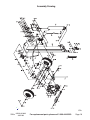
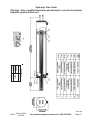
LOG SPLITTER
WITH ROBIN® ENGINE
MODELS 91839, 91840 & 92199
ASSEMBLY AND OPERATING INSTRUCTIONS
WARNING!
IMPORTANT INFORMATION
This trailer’s Hitch Coupler MUST be
properly secured to the hitch ball of the towing
vehicle. After assembly and attachment, pull
up and down on the Hitch Coupler to make
sure the hitch ball is fitting snugly in the Hitch
Coupler. There must be no play between the
hitch ball and Hitch Coupler. If there is play,
tighten the Adjustment Nut until no play is
present. If the Adjustment Nut is too tight, the
Handle will not lock. Carefully read and follow
the complete instructions in this manual
BEFORE setup or use.
If the Coupler is not secured
properly, the ball could come loose
while the trailer is in motion, possibly
causing property damage, SERIOUS
PERSONAL INJURY, or DEATH.
3491 Mission Oaks Blvd., Camarillo, CA 93011
Visit our Web site at http://www.harborfreight.com
Copyright© 2004 by Harbor Freight Tools®. All rights reserved. No portion of this
manual or any artwork contained herein may be reproduced in any shape or
form without the express written consent of Harbor Freight Tools.
For technical questions and replacement parts, please call 1-800-444-3353.
REV 11/04; REV 02/06
Specifications
Log Capacity
25” Long, 8” Diameter
Tire Air Pressure
60 PSI Cold
Wedge Size
7-1/8” Tall
Overall Dimensions 79-1/4” x 42-1/2” x 37-1/4”
Hydraulic Fluid
Capacity
2.5 Gallons
Toe Plate Thickness
1-5/8”
Wheel Size
8” Diameter, D.O.T.
Approved
Ram Diameter
1-3/4” Overall
S K U 91839
S K U 91840
S K U 92199
Engine
9HP EX-27 Robin®
Engine
9HP EX-27 Robin®
Engine
6HP Robin®
Cylinder Diameter
4-1/2”
Cylinder Diameter
5”
Cylinder Diameter
4.5”
24
Tons of Force
30
Tons of Force
Tons of Force
Pump
Haldex®
Weight
11 GPM, 2Stage Gear
4 9 8 L b s.
Pump
Weight
Haldex®
16 GPM, 2Stage Gear
6 4 0 L b s.
Pump
Weight
22
Haldex®
11 GPM, 2Stage Gear
4 9 2 L b s.
This product requires engine oil, hydraulic oil, and fuel to be added before starting.
Attempting to start the engine without oil will ruin the engine and void the warranty.
Before starting the engine, refer to the engine owners manual for additional engine
maintenance information.
Note: 8” maximum diameter applies to most soft to medium types of woods. Maximum
diameter of hardwoods may vary depending on density of the wood.
Note: Read and follow the instructions and safety warnings in the manual that accompanies the Robin® engine. Engine specifications are listed in the engine manual.
Save This Manual
You will need the manual for the safety warnings and precautions, assembly instructions,
operating and maintenance procedures, parts list and diagram. Keep your invoice with this
manual. Write the invoice number on the inside of the front cover. Keep the manual and
invoice in a safe and dry place for future reference.
Safety Warnings and Precautions
WARNING: When using tool, basic safety precautions should always be followed to reduce the risk of personal injury and damage to equipment.
Read all instructions before using this tool!
1.
Keep work area clean. Cluttered areas invite injuries.
2.
Observe work area conditions. Do not use machines or power tools in damp or wet
locations. Don’t expose to rain. Keep work area well lighted.
3.
Keep children away; this unit may produce hazardous flying debris. Children must
never be allowed in the work area. Do not let them handle machines or tools.
4.
Store idle equipment. When not in use, tools must be stored in a dry location to inhibit
rust. Always lock up tools and keep out of reach of children.
RAV 01/07
91839, 91840
For
replacement
parts,
please
call
1-800-444-3353.
Page 2
SKUs
& 92199
5.
6.
7.
8.
9.
10.
11.
12.
13.
14.
15.
16.
17.
18.
19.
20.
Use the right tool for the job. Do not attempt to force a small tool or attachment to do the
work of a larger industrial tool. There are certain applications for which this tool was
designed. It will do the job better and more safely at the rate for which it was intended.
Do not modify this tool and do not use this tool for a purpose for which it was not intended.
Dress properly. Do not wear loose clothing or jewelry as they can be caught in moving
parts. Protective, electrically nonconductive clothes and nonskid, steel toe footwear are
recommended when working. Wear restrictive hair covering to contain long hair.
Use eye protection. Always wear ANSI approved impact safety glasses underneath a
full face shield. Wear an ANSI approved dust mask or respirator when working around
wood dust.
Do not overreach. Keep proper footing and balance at all times. Do not reach over or
across the Log Splitter.
Maintain tools with care. Keep tools sharp and clean for better and safer performance.
Follow instructions for lubricating and changing accessories. Inspect tool hoses periodically, and if damaged, have them repaired by an authorized technician. The handle must
be kept clean, dry, and free from oil and grease at all times.
Remove adjusting keys and wrenches. Check that keys and adjusting wrenches are
removed from the tool or machine work surface before plugging it in.
Never leave the Log Splitter unattended while in operation.
Stay alert. Watch what you are doing, use common sense. Do not operate any tool
when you are tired.
Never attempt to split two logs on top of each other.
Check for damaged parts. Before using any tool, any part that appears damaged
should be carefully checked to determine that it will operate properly and perform its
intended function. Check for alignment and binding of moving parts; any broken parts or
mounting fixtures; and any other condition that may affect proper operation. Any part
that is damaged should be properly repaired or replaced by a qualified technician. Do
not use the tool if any switch does not turn On and Off properly.
Always operate the Log Splitter on a dry, flat, level surface with the wheels blocked.
Replacement parts and accessories. When servicing, use only identical replacement
parts. Use of any other parts will void the warranty. Only use accessories intended for
use with this tool. Approved accessories are available from Harbor Freight Tools.
Do not operate tool if under the influence of alcohol or drugs. Read warning labels
if taking prescription medicine to determine if your judgment or reflexes are impaired
while taking drugs. If there is any doubt, do not operate the tool.
Maintenance. For your safety, service and repairs should be performed regularly by a
qualified technician. Maintenance should be performed regularly.
Never place your hands or body near a hydraulic fluid leak. Never check for a leak
with your hands or other body parts. High-pressure fluid can be forced under your skin
resulting in serious injury.
Never place hands or feet between the log and splitter wedge, or between the log
and the ram during the forward or reverse stroke.
SKUs
91839, 91840
& 92199
For replacement parts, please call 1-800-444-3353.
Page 3
21.
This equipment must never be used in any sealed structure. Carbon monoxide is produced during operation and is DEADLY in a closed environment.
Early signs of carbon Monoxide poisoning resemble the flu, with headaches,
dizziness, or nausea. If you have these signs, the tool may not be working properly or is improperly vented, get fresh air immediately.
22.
Never split a log that contains any foreign materials.
23.
WARNING: The brass components in this product contain lead, which is a chemical
known to the State of California to cause cancer and birth defects or other reproductive
harm. (California Health & Safety Code § 25249.5, et seq.)
24.
People with pacemakers should consult their physician(s) before using this product. Electromagnetic fields in close proximity to a heart pacemaker could cause
interference to or failure of the pacemaker.
Warning: The warnings, cautions, and instructions discussed in this instruction manual
cannot cover all possible conditions and situations that may occur. It must be understood by the operator that common sense and caution are factors which cannot be
built into this product, but must be supplied by the operator.
Unpacking
When unpacking, check to make sure the parts listed on page 9 are included. If any
parts are missing or broken, please call Harbor Freight Tools at the number on the cover of
this manual as soon as possible.
Assembly
Note: Because of the weight and size of the Log Splitter, assembly should be done with the
help of another person.
Attaching the Tires
Refer to the Assembly Drawing on page 9 and FIGURE 1 on page 5.
1.
Position the Tires (48) next to each of the Axles located on the bottom of the Oil Tank
Assembly (10). The Tires (48) come completely assembled.
2.
Make certain to pack the bearings as explained in the included insert.
3.
Put a Seal (59) and Bearing (49) on the Axle and then put the Tire (48) on the Axle.
4.
Follow the Bearing Packing Instructions as explained on the last page of this
manual. With each Tire (48) in place, add a Washer (50) and a Spindle Nut (51) onto
the ends of the Axles. Tighten the Spindle Nuts (51) to 20-25 ft. pounds, and turn each
tire several times to seat the bearing. Back off the Spindle Nut (51) one half turn. Insert
a Cotter Pin (25) through both the Axle and the Spindle Nut (51) and bend the end of
the Pin back to hold it in place. Lastly, tap on a Wheel Cap (61).
The Tire (48) assembly is now complete. Note: It may be necessary to reset the wheel
bearings after the Log Splitter has been towed.
The wheel manufacturer states the maximum speed is not to exceed 40 MPH. The tires
are DOT approved for public roads; however, this item is not for use on public roads or
highways.
REV 11/04
SKUs
91839, 91840
& 92199
For replacement parts, please call 1-800-444-3353.
Page 4
Assembly (continued)
Connecting the Rail Assembly (2) to the Oil Tank Assembly (10B)
1.
Insert the Front Leg Assembly (11) into the bracket on the Oil Tank Assembly (10B).
Insert the remaining Hex Head Bolt (16) through the hole in the middle of the bracket of
the Oil Tank Assembly (10B). Secure it with a Hex Head Nut (17). Refer to the Hex
Head Nut (17) attached to the Hex Head Bolt (16) at the top of the Front Leg Assembly
(11) in FIGURE 1 below. Note: When travelling, remove the Push Pin (26) and Hair
Pin Clip (29) and lift the Front Leg Assembly up so that it is parallel to the Rail Assembly (2). Then, replace the Push Pin (26) and Hair Pin Clip (29) into the Horizontal
Transport Hole shown just above the Oil Plug (37), in FIGURES 1 and 2.
2.
To connect the Rail Assembly (2) to the Oil Tank Assembly (10B), insert a Hex Head
Bolt (16) into the middle hole of the “L” shaped bracket on the Oil Tank Assembly
(10B). Secure it with a Hex Head Nut (17). Refer to the Hex Head Nut (17) attached to
the Hex Head Bolt (16) just above the tire in FIGURE 1 below. Insert the Push Pin (26)
through the hole, as shown in FIGURE 3.
3.
In FIGURES 1 and 2, the Rail Assembly (2) is shown in Horizontal mode for operation
and travel (as mentioned above, the Front Leg Assembly (11) must be secured up in
the horizontal position when travelling). For vertical operation see page 6.
FIGURE 1
Slide Assembly (3)
Safety Chain
with Hook (4)
Base
Cylinder (1)
Place Log Here
Hitch Coupler (9)
Hex Head Nut (17) is attached to Hex Head Bolt (16)
Horizontal transport hole
Push Pin (26) and
Hair Pin Clip (29)
Push Pin (26)
Oil Plug (37)
with air inlet hole
Rail Assembly (2)
Vertical Position Hole
Hex Head Nut (17) is attached
to Hex Head Bolt (16)
Front Leg Assembly (11)
Vertical position
locking hole
Oil Removal Plug
Oil Tank (10B)
Wheel Cap (61)
FIGURE 3
FIGURE 2
Horizontal transport hole
Second Push Pin (26) secures
Rail Assembly (2), and is removed
for vertical log splitting.
Air Inlet Hole
Push Pin (26)
Close-up of Push Pin (26) securing the
Front Leg Assembly (11) to the bracket
on the Oil Tank Assembly (10B).
SKUs
91839, 91840
& 92199
Oil Plug (37)
with air inlet hole
For replacement parts, please call 1-800-444-3353.
Page 5
Transportation
CAUTION
Care must be taken when backing up
When transporting the Log Splitter, make sure
the Trailer; only back up the trailer on a
your hitch (not included) is compatible with the straight path. If the Trailer is allowed to turn
Hitch Coupler (9). Follow all of the safety warn- off the straight path while backing up, the Trailer
ings for towing in your vehicle’s manual. Always could jackknife, causing severe damage to the
trailer and to the towing vehicle.
use the Safety Chain with Hook (4) when towing
a vehicle. Do not tow the Log Splitter at speeds
above 45 MPH. As mentioned in number 2 on page 5, always travel with the Front Leg
Assembly (11) in the horizontal position. The Rail Assembly (2) must always be secured
in the horizontal position for travelling. Note: Make sure the air inlet hole on the Oil Plug
(37) is covered when transporting. See FIGURE 3 on page 5, and refer to number 2 in
Operation below.
Pull up and down on the Hitch Coupler to make sure the hitch ball is fitting snugly in the
Hitch Coupler. There should be no play between the hitch ball and Hitch Coupler. If there
is play, tighten the Adjustment Nut until no play is present. If the Adjustment Nut is too
tight, the Handle will not lock.
Note: The hitch will accept 2 inch hitch balls.
FIGURE 4
Operation
Warning!! Always block the wheels before changing the
position (vertical/horizontal) of the unit.
In FIGURE 1, the Rail Assembly (2) is shown in Horizontal mode for operation and travel. In FIGURE 4 the unit is
shown in the vertical position. To change positions, remove the Hair Pin Clip (29) and the Push Pin (26). A
close-up of this Push Pin (26) is shown in FIGURE 3 on
page 5. Tilt the unit to the vertical position as shown in
FIGURE 4, and replace both the Push Pin (26)
and the Hair Pin Clip (29) into the vertical posi- Base
tion hole (See FIGURE 1). Reverse the process
to return to the horizontal position.
Vertical Position
Place
Log
Here
1.
Remove the Oil Plug (37) and fill the tank with Hydraulic oil (not included). To check the
oil level remove the Dipstick (62), check the level then replace it. The oill should be at
the upper notch of the Dipstick. Be sure that a constant oil level of 2.5 gallons is maintained. See FIGURE 3 on page 5, Parts List page9, and Assembly Diagram page 10.
2.
The hydraulic system must be vented during operation or it may become vacuum locked
and stop working properly. To vent the system, open the air inlet hole (See FIGURE 3)
by loosening the Oil Plug. You may have to move the o-ring to expose the air inlet vent.
When the Log Splitter is not in operation or being transported, close the air inlet hole by
tightening the Oil Plug (37).
3.
Make certain that the maximum length of each log does not exceed 25 inches with a
diameter of 8 inches.
SKUs
91839, 91840
& 92199
For replacement parts, please call 1-800-444-3353. 07e Page 6
Operation (continued)
4.
Place the log on the Splitter Base as shown in FIGURES 1 and 4. Make sure the
wedge on the Slide Assembly (3) is facing the log. (See FIGURE 1).
5.
After reading and following all of the setup, safety, and operation warnings in the Robin®
Operating Manual, turn on the engine. See FIGURE 5. Set the engine’s throttle all the
way to the fast setting (represented by the rabbit, left in the picture below).
FIGURE 5
(9 HP Engine Shown)
Throttle
Choke
Starter Cord
WARNING!! Stand clear of the splitting area. No spectators should be within
twenty feet of the log splitting area. Wood projectiles can fly in any direction.
FIGURE 6
6.
Grip the Directional Valve (58) and move
it into the lower position to move the
Slide Assembly (3) toward the log to split it.
7.
Once the log is split, remove the split pieces.
To back the wedge off the log, move the
Directional Valve (58) away from the log
you just split.
Directional Handle (58)
To stop movement of the Log Splitter at any time, move the Directional Valve
(58) into the midpoint. Do not ever go near the splitting area if the Slide
Assembly (3) is moving.
8.
Continue repeating the above steps until all of the logs are split.
SKUs
91839, 91840
& 92199
For replacement parts, please call 1-800-444-3353.
Page 7
Maintenance
The engine must be off when performing any maintenance. If the unit was
recently used, make sure that the engine has cooled to avoid burns.
1.
After every use, wipe down the Log Splitter to remove any tree sap or dirt. This will extend the
life of the unit. Always keep the wedge and base clean.
2.
When storing, make sure the Log Splitter is locked in a location where children cannot reach it.
3.
Read the maintenance section of the engine manual and follow all of the procedures.
Note: The recommended interval for changing the hydraulic oil and filter is approximately every 3
months.
4.
BEFORE TRANSPORTING, inspect the general condition of the Trailer. Check for loose Bolts
and Nuts, misalignment or binding of moving parts, cracked, bent, or broken parts, excessively worn Safety Chain , damaged Tail Lights/Side Running Lights/Wiring Harness, loose Lug
Nuts, loose Hitch connection, and any other condition that may affect its safe operation. If
abnormal noise or vibration occurs, have the problem corrected before further use. Do not
use damaged equipment.
5.
BEFORE TRANSPORTING, check the Tires for wear and proper inflation (60 PSI).
6.
BEFORE TRANSPORTING AND AT 500 MILE INTERVALS DURING EVERY TRIP, check
and tighten the Tire Lug Nuts. Torque from 85 to 90 Ft.-Lbs.
7.
EVERY 2,000 TO 3,000 MILES OF TRAVEL, lubricate the Hub Assemblies with a heavy weight
bearing grease. Follow the Bearing Packing Instructions as explained on the last page of
this manual. After each Hub Assembly is reassembled, tighten the Castle Nut until the wheel
starts spinning with slight resistance. Loosen the Castle Nut about 1/2 turn from this point.
Insert a new Cotter Pin through the Castle Nut and the hole in the axle. Bend the Pin back,
locking it and the Nut in place.
Bleeding the Hydraulic System
If the Log Splitter begins to lose power or splitting efficiency, it may be a result of air becoming trapped
in the hydraulic system. Follow the steps below to bleed air from the system.
1.
Loosen the Oil Plug (37) and make sure the o-ring is out of the way to expose the air hole in the
Oil Plug (37).
2.
Remove the spark plug from the engine (see engine manual) to keep the engine from starting
during this process.
3.
Push the Directional Valve (58) forward, toward the front of the Cylinder (1) (see FIGURE 1).
4.
Pull the engine starter cord 10-15 times until the hydraulic cylinder piston moves forward.
CAUTION: Keep everything away from the splitting edge during this process.
5.
Tighten the Oil Plug (37).
6.
Replace the spark plug.
7.
Test the Log Splitter to make sure it is operating properly. If not, repeat the above process.
Warning! Only a qualified technician should repair or service the internal hydraulic system of this unit.
SKUs
91839, 91840
& 92199
For replacement parts, please call 1-800-444-3353.
Page 8
Parts List
When ordering parts, be certain to note which Sku number they are for.
Par t
Description
1
Cylinder
Qty. Par t
1
Description
Qty.
32
High Pressure Hose
1
2
Rail Assembly
1
33
Return Hose
1
3
Slide Assembly
1
34
Inlet Hose
1
4
Safety Chain With Hook
1
35
Hose Clamp
4
5
Slide Guide
2
36
Male Connector
1
6
Slide Retainer
2
37
Oil Plug
1
7
Bolt 1/2''*2-1/2''
6
38
High Pressure Fitting
1
8
Hex Nut 1/2''
7
39
90° Elbow Fitting #2
2
2
9
Hitch Coupler
1
40
90° Elbow Fitting #3
10B
Oil Tank Assembly
1
41
Hex Head Bolt 3/8''*3/4''
1
11
Front Leg Assembly
1
42
Hex Head Bolt 5/16''*1''
4
12
Hex Head Bolt 1/2''*1-3/4''
2
43
Oil Filter
1
13
Hex Nut 1/2''
2
44
Pump Mounting Bracket
1
14
Hex Head Nut 3/8''
3
45
Pump
1
15
Washer 1/2''
2
46
Hex Head Bolt 5/16''*1''
4
16
Hex Head Bolt 9/16''*1-1/4''
2
47
Hex Head Bolt 3/8''*3-1/4''
2
17
Hex Nut 9/16''
2
48
Tire
2
18
Washer
1
49
Bearing 30205E
4
19
Hex Head Bolt 5/16''*2-3/4''
1
50
Washer 3/4''
2
20
Hex Head Nut 3/8''
1
51
Spindle Nut
2
21
O Ring Seal
1
52
Coupling -Pump Side
1
22
Hex Head Bolt 1/2''*1-3/4''
4
53
Coupling -Engine Side
1
23
Hex Nut 5/16''
4
54
Pump Key 1/8''
1
24
Spring Washer 5/16''
8
55
Engine Key
1
25
Cotter Pin
2
56
Hex Screw
2
26
Push Pin
2
57
Engine*
1
27
Clevis Pin
1
58
Directional Valve
1
28
Hair Pin Clip
2
59
Seal
2
29
Hair Pin Clip 2.5''
2
60
Hex Head Bolt 3/8''*3-1/2''
1
30
Slide Holder
1
61
Wheel Cap
2
31
Hydraulic Tubing
1
62
Dipstick
1
*The parts list for the Engine (57) is in the separate Robin® Engine Manual.
PLEASE READ THE FOLLOWING CAREFULLY
THE MANUFACTURER AND/OR DISTRIBUTOR HAS PROVIDED THE PARTS DIAGRAM IN THIS
MANUAL AS A REFERENCE TOOL ONLY. NEITHER THE MANUFACTURER NOR DISTRIBUTOR MAKES ANY REPRESENTATION OR WARRANTY OF ANY KIND TO THE BUYER THAT
HE OR SHE IS QUALIFIED TO MAKE ANY REPAIRS TO THE PRODUCT OR THAT HE OR SHE
IS QUALIFIED TO REPLACE ANY PARTS OF THE PRODUCT. IN FACT, THE MANUFACTURER
AND/OR DISTRIBUTOR EXPRESSLY STATES THAT ALL REPAIRS AND PARTS REPLACEMENTS SHOULD BE UNDERTAKEN BY CERTIFIED AND LICENSED TECHNICIANS AND NOT
BY THE BUYER. THE BUYER ASSUMES ALL RISK AND LIABILITY ARISING OUT OF HIS OR
HER REPAIRS TO THE ORIGINAL PRODUCT OR REPLACEMENT PARTS THERETO, OR ARISING OUT OF HIS OR HER INSTALLATION OF REPLACEMENT PARTS THERETO.
NOTE: Some parts are listed and shown for illustration purposes only and are not available
individually as replacement parts.
SKUs
91839, 91840
& 92199
For replacement parts, please call 1-800-444-3353. 07e Page 9
Assembly Drawing
61
07e
SKUs
91839, 91840
& 92199
For replacement parts, please call 1-800-444-3353.
Page 10
Hydraulic Ram Seals
Warning! Only a qualified technician should repair or service the internal
hydraulic system of this unit.
Part Sku
26671
28872
Seal Kits
Model
91839
92199
91840
REV 10/05
91839, 91840
SKUs
& 92199
For replacement parts, please call 1-800-444-3353.
Page 11
Hydraulics Drawing
Bearing Packing Instructions
Important
Read and adhere to the following instructions; failure to read and obey all of the
following instructions COMPLETELY will void the warranty and can result in damage to
the trailer, property damage, or SERIOUS PERSONAL INJURY.
Whenever a hub is disassembled (if a hub on a new unit requires assembly or a hub is
disassembled for maintenance), the following procedure MUST be followed.
1.
Using a suitable solvent, thoroughly clean the bearings and the rest of the parts in the Hub
assembly of all grease, dirt, metal shavings, or any other foreign object. The parts must be
cleaned even if they are new or appear clean.
2.
Allow all pieces to dry completely.
3.
Make sure that your hands are thoroughly clean and the bearing packer (not included) is also
thoroughly clean.
4.
Place fresh, clean bearing grease in the packer.
5.
With the grease-filled bearing packer in one hand and the bearing in the other, press the bearing into the grease, forcing the grease inside the slots in the bearing, continue doing this until
every slot in the bearing is completely full of grease.
6.
Finish assembling the hub/wheel assembly as explained in this manual, being careful not to
get any dirt or debris on any part of the assembly.
SKUs
91839, 91840
& 92199
For replacement parts, please call 1-800-444-3353.
Page 12