1
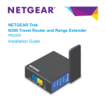
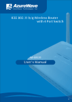
White Paper
Troubleshooting Your Industrial Network
Ethernet is rapidly spreading across a wide range of
industrial environments. This standardized, plug-and-
Table of contents
play technology is easy to install and it works 99%
Root causes of LAN Problems. . . . . . . . . . 2
of the time. But when it doesn’t, it is not so easy to
Best practices for successful
understand why. With more devices being added to
the network and fewer people on the floor, most
production and maintenance engineers are under a
lot of pressure - especially since all plants want to
run faster, with minimal downtime.
This whitepaper explores some of the key troubleshooting causes and issues for industrial networks
and what you can do to quickly recognize, locate,
and solve them.
LAN troubleshooting. . . . . . . . . . . . . . . . . 3
Troubleshooting cabling issues . . . . . . . . 3
Troubleshooting signaling issues . . . . . . . 4
Troubleshooting tips for electrical
signal integrity. . . . . . . . . . . . . . . . . . . . . . 5
Troubleshooting network issues. . . . . . . . 6
Summary . . . . . . . . . . . . . . . . . . . . . . . . . . 7
White Paper
Root causes of LAN problems
Since industrial Ethernet is the result of the trend in equipment moving from analog to digital signaling, network communication now
has three elements:
1. The Physical Layer: This is the cable infrastructure that transmits signals. It can be copper, fiber or wireless.
2. The Network Layer: This is the Ethernet and Internet Protocol (IP) that controls the data communication.
3. Electrical Signaling: Digital signals from equipment pass through switches and VLANs to convey the data.
In order to establish error-free data communication, troubleshooting must establish that the cabling is good, digital signaling is
consistent, and the communication protocol for the equipment is operating correctly.
Proposed foundation fieldbus H1/HSE
control
system architecture
Proposed
foundation
fieldbus H1/HSE
control system architecture
Operator interface
Operator interface
Engineer interface
Data analysis,
Data analysis,
model
creation,
model creation,
control strategy
control strategy
creation
creation
Engineer interface
Operator interaction,
Operator interaction,
history collection
history collection
Ethernet
Ethernet
FFB
MVC
FFB
Linking Device
MVC
Linking Device
Demethanizer
field
instruments
Demethanizer
AI
PID
Multi-variable
Multi-variable
control &
control &
computing
generalgeneral
computing
HSE communication
HSE communication
links
links
Linking Device
Linking Device
Demethanizer
field instruments
PID
field
instruments
HSE coprocessor
HSE coprocessor
AO
Demethanizer
field instruments
AI
AO
Fluke Networks
2
www.flukenetworks.com
White Paper
Best practices for successful LAN troubleshooting
Troubleshooting downtime issues can be time-intensive and costly. Following a standardized troubleshooting procedure will help save you
countless hours.
The basic troubleshooting sequence consists of these steps:
1.Document your network. A diagram of the parts of the network, as well as the signal flow paths between various devices, is
enormously helpful in visualizing the problem and saving valuable time. Theory and practical experience will determine which test to
perform first. Consider experience with the same or similar equipment and related symptoms, as well as the probability of what is likely to fail or what suffers from repeated failures. A good practice is to start with the physical layer and work your way up the
protocol stack.
2.Collect all available information and analyze the symptoms. Ask yourself if you understand the symptoms, and verify or recreate
the reported problem yourself if possible.
3.Localize and isolate the problems. It’s best to subdivide or isolate the problems into a smaller function section – removing the
largest convenient section first. As you go step-by-step, eliminate culprits.
• If you can ping or simulate signals and get a response, you know there’s power.
• If the device is properly connected, then you can proceed to the control or management device.
• Look at the PLC for error codes. You might discover, for example, that it received several bad packets of information,
which caused it to turn off a particular port in order to protect the rest of the network.
The overall troubleshooting strategy is to divide and conquer, test and eliminate. You may not know why the signal did not come back,
for example, but at least you’ll know that you have a problem with the cable. Start at any convenient spot near the center point of the
problem and divide the problem in half. Continue “halving” the problem until you’ve isolated it to the smallest possible section.
4.Document what you did. Documentation can be used for future reference to help you troubleshoot the same or similar problems.
You can also use the documentation to prepare reports on common network problems for management and or departments,
or to train new hires or members of the network-support team.
Following this basic regimen, let’s take a close look at the specific troubleshooting issues you are likely to encounter in each of the three
major areas of the network, beginning with cabling infrastructure.
Troubleshooting cabling issues
Poor cable terminations or cable faults
If a cable is suddenly cut, the symptom experienced may be that the system simply stops. Or, with faulty cross-connection through
a junction, for example, you may start getting CRC or FCS errors. These types of errors indicate incomplete signals being transmitted.
The PLC has detected corruption in a frame that contains critical information and throws the frame away. Now the PLC is still waiting for
that information – the temperature of the glue for the labels on the bottles, for example – so it asks again. If the re-transmission isn’t
successful because of the faulty cable, either the system aborts, or the line produces bottles without labels because the glue wasn’t the
correct temperature to adhere.
Insufficient cable rating
In a heavy industrial environment such as mining, for example, cable may be at risk from temperature extremes, water, or being run over.
Without sufficient protection, the insulation might soak through, be cut, or short circuit. Standard office Ethernet cabling doesn’t stand
Fluke Networks
3
www.flukenetworks.com
White Paper
a chance under these conditions. Make sure both cabling and connectors have the appropriate IP ratings to withstand the particular
hazards of your environment. In addition, use protective cabling in any areas with repetitive motion or an area that a link might be
stepped on or crushed. Many cable manufacturers offer specific cabling with boots and/or advanced engineered material cable jackets
specifically for harsh environments.
Issue with connectors
Not only the cable, but also all the components of a network on a manufacturing floor must be different from those used in office
environments and datacenters. In areas with extreme temperature swings, high humidity, or chemical or high- pressure washes, consider
robust connectors and components like the M12 connector. The M12 is a popular 4-pin connector with a rubberized boot in diameters
ranging from 6.0mm to 6.7mm. It has been used in industrial and production environments to transmit power and signals to optical
sensors for decades. In newer installations, it is also being used for bidirectional communications such as Cat 5e or 100 MHz. If you’re
using RJ-45, the IP67 rating is reached by using sealed connectors.
It is also important to understand any external machinery noise issues when deciding between UTP (unshielded), STP (shielded) or fiber
optic components.
Contaminated fiber optic cable end faces
Microscopic fiber optic cable is particularly susceptible to contaminants clogging the ends. When light can’t pass through, this causes
reflectance. The signal is not fully transmitted and communication breaks down. One international transportation system, for example,
discovered that fine dust from routine wear on the rubber train tires was clogging the fiber optic communication cable. Trains were not
reliably receiving information about whether or not another was on the track ahead, activating safety features that automatically stopped
the trains. Unhappy commuters were kept waiting because of dust.
Troubleshooting signaling issues
Once you’ve eliminated cabling problems, you can move to the next major area of concern: electrical signaling issues. Here are some of
the more troublesome ones.
Device installation errors
A common and difficult-to-troubleshoot issue is misconfigured devices. The original installer must select the speed of the connection
between the switch and sensor. They also can choose full- or half-duplex communication. But what if the sensor is configured for half
duplex, and the switch on the other end is set to full duplex in error? If the switch has something to say, it says it. Now what happens
when the poor sensor tries to talk? “I’ve detected the speed of liquid.” While the sensor transmits, the switch transmits at the same
time. The sensor reacts: “Uh oh – somebody else transmitted. I need to stop, wait a moment and listen again.” Now that the switch has
stopped talking, the sensor re-sends the message, and again, coincidentally, the switch transmits at the same time. Duplex mismatch
error is very difficult to detect. When you troubleshoot, you’ll find that the cabling is fine. Both switch and sensor are connected. There is
little traffic. The only clue is that delay or latency will be extremely variable. As a result, the network appears “slow.” It is helpful to have
a tester that can tell you the configuration of each device so you can find a mismatch like this.
Device failures caused by a harsh electrical environment
Devices (Ethernet or proprietary) connected in an industrial network translate control-system variables and commands into digital
information. These electrical signals in the form of digital ones and zeros are then transmitted across copper cables, network switches,
and repeaters to and from the control room. These electrical signals are not impervious to the harsh electrical and climatic environment
found in industrial plants and factories. Several factors can influence or degrade the electrical signaling, affecting the performance of the
network. High-energy sources such as lighting systems and heavy-duty machinery create electrical interference. Noise, static discharge,
and transients can cause network devices to reset or fail. Monitoring the network, one segment at a time can capture these events,
helping you isolate their source.
Fluke Networks
4
www.flukenetworks.com
White Paper
Improper cable installation
Issues like excessive cable lengths, using the incorrect grade of cabling, loose or corroded connections, or simply too many or incorrect
network terminations can attenuate and distort electrical signals causing excessive retransmissions or interruptions. Other cable installation issues that affect electrical signals include:
• Improper ground connections
• Tight bend radius
• Worn or broken cable shielding or connectors
Heavy equipment operation
Operating in the proximity of equipment that radiates electromagnetic waves such as motors, induction furnaces and lighting systems,
can distort and interrupt the electrical signaling. Any device or segment in an automation or process control system with electrical signal
quality issues can affect the overall performance of the Ethernet network.
High-voltage electrical loads
Transients, surges, and harmonics are the most common electrical phenomena found on high-voltage electrical feeder and branch circuits
with breakers and non- linear loads. These and other phenomena like static discharge from rotating machinery can cause disturbances to
electrical signals. Ground-loop currents are also notorious for creating erroneous equipment failures that are hard to diagnose.
With attention to proper installation practices, minimizing sources of electrical disturbances, and using appropriately IP-rated devices
you can mitigate many of these problems.
Troubleshooting tips for electrical signal integrity
As for all three areas of the network, use the standard troubleshooting protocol when tracking down signaling problems.
1. Always baseline network signaling by capturing waveforms and measurements at commissioning. Use these as a reference point,
looking for any significant changes.
2. Start at one side of the trunk, make measurements along the network cable at every junction or connection point.
• Document key parameters at each point
• Look for significant changes
• The further away from the power source, the more attenuation you should expect to see
• Isolate sections one at a time, testing to see if signaling returns or improves
• Isolate suspicious devices by removing them one at a time, testing to see if signaling returns or improves
3. Things to look for:
• Changing DC offsets or waveform fluctuations, indicating grounding problems
• Excessive high impulses or transients, evidence of HV equipment radiating energy onto the cabling
• Correlations between changes and external events like equipment turning on or off.
Fluke Networks
5
www.flukenetworks.com
White Paper
Troubleshooting network issues
The Open System Interconnection (OSI) model, a technology standard maintained by the
International Standards Organization (ISO), defines seven layers of network protocols and
equipment communications and interoperation. For day-to-day testing of layers 1 through
3 (1 is Physical, 2 is Data Link, 3 is Network) you can perform a series of basic tests.
• First, test at the outlet where you connect your device. Is the device connected to a
Application
Presentation
Session
Transport
switch on far end? Is the data switch open on the far end? If it is open, the tester
Network
will tell you at what length the cable is open. Either it is not connected or cut.
Data Link
• If the device is connected to the switch, how is the switch configured? Is it set at
Physical
10 mb or 100 mb, half duplex or full duplex?
• Now measure utilization in the collision domain where it is attached.
Connect to the network and request IP address to verify that the DHCP server is connected to network. Ping tests ensure that the network
is turned on and devices and servers are properly connected.
Proper VLANs and multicasting segmentation
Before switch features became complex and varied, a Local Area Network (LAN) described all of the PCs and other devices connected to
hubs, bridges, and switches on one port of a router. The router defined the end of what was called a broadcast domain. Everything
attached to that router port was within that broadcast domain, network, or LAN (depending on which term was appropriate for the
discussion). To change router ports was to change broadcast domains.
When switch features became more complex, it became possible to logically divide the switch into different broadcast domains. Instead
of being physically separated from another broadcast domain by the interconnection of a different set of hubs, bridges, and switches
attached to a router port, it is now possible to logically separate them via the switch configuration. This logical separation is called a
Virtual LAN (VLAN).
In an industrial network, you may encounter cases of sensors in the network sending their information to multiple addresses instead of
transmitting to the single, relevant address. A pressure sensor, for example, sends its measurements to bottling, labeling, and capping,
instead of sending only to the bottling machine. It broadcasts to all the machines: “here’s the pressure”. This causes unexpected network
traffic. Or if the bottling line is not correctly segmented from regular network traffic, it may send the bottling-machine pressure information (a time-critical packet of information) at the same time as dozens of people in the corporate network are busily downloading a new
network security fix, causing major ramifications on the production line. This could easily happen just by someone adding a port and
connecting it wrong. But as a result of mixing the office and production “highways” – you get unexpected variable traffic.
On the industrial side there is not as much variability in traffic, but there is much greater sensitivity to the delay or latency. When a sales
manager is downloading his forecast file and it takes 20 seconds longer, he might not even notice. In the bottling line, the difference
between 25 milliseconds and 2000 milliseconds may result in bottles without labels.
Duplicate IP addresses and unexpected service behavior cause network havoc
These are problems that could adversely affect any LAN, but in an industrial network, the repercussions are more severe. Each device
operates with a unique IP address. IP addresses are used when end devices communicate point-to-point. Every PLC, switch, and Ethernetenabled sensor must have a unique IP address in order to operate normally. In an automation network, the communication between
switch and PLC is restricted to only one area of control or task, called point-to-point, and each device is individually commanded to
perform its task. These IP addresses may be either dynamically assigned (DHCP), automatically assigned a fixed address (DHCP or BOOTP),
or manually assigned (static). If a duplicate IP address appears, either because a mix of dynamic and static addressing was used, or the
static address was accidently duplicated, then either the commands for one specific PLC will be sent to both PLCs using the same IP
address, or one PLC will operate normally for periods of time while the other fails to work at all. In either case, the affected PLCs will
not be able to operate reliably. This is a difficult problem to identify from symptom analysis.
Fluke Networks
6
www.flukenetworks.com
White Paper
In addition, a DHCP server will attempt to allow a PLC to keep using the same IP address forever. However, if one of many situations
arises on the network, the DHCP server will tell the PLC to begin using a different address. When this happens, it is possible that the
controller managing the PLC will not know about the address change and the PLC will cease to operate because the controller is suddenly
unable to talk to it.
A good network tester will reduce troubleshooting of this sort of problem from hours to minutes.
Margin analysis
You add one more sensor, maybe to measure the temperature of the bottles so the labels will adhere properly. That adds traffic. How will
the HMI to PLC perform? Maybe you’ve upgraded your user interface to that lovely touch screen. But that adds traffic, so when you push
buttons there’s no (or slow) response. The question you need to continually ask is: if my traffic patterns change, how much will that
affect performance?
Non-deterministic network behavior
If, for example, the symptom is a significant variation in latency, you can measure throughput, delay or latency, and jitter, and compare
these to baselines for network and confirm that performance is in line with expected. If the symptom is excessive latency or delay, look
at all the devices attached. What is the utilization level (or the number of cars on the highway)? Maybe you find excessive utilization of
a collision domain. Look at the traffic. Do all these “cars” belong here? Find out where they are come from and where are going? Suddenly
you’re seeing “logging trucks” where you’re expecting compact cars! Now you need to find out why this unanticipated traffic is suddenly
showing up on this highway and where it came from to track down the problem.
Measuring determinism means the ability to accurately understand the worst-case time-to-exchange information end-to-end, regardless
of what other network traffic is occurring. In troubleshooting non-deterministic behavior, it is important to consider not only throughput
and latency or delay, but also variability and jitter. These measurements must also be made with traffic present or a real-time operation.
Make these measurements across an individual switch or across a wide area global network.
Network uptime is crucial to profitability and the quality of your output
Networks aren’t perfect and being able to troubleshoot quickly and effectively is fundamental to your production process. One failure can
trigger another, resulting in a significant loss of time and money. This paper has given you a brief overview of the many issues that could
impact productivity in the three major areas of Industrial Ethernet: the cabling infrastructure, electrical signaling, and the network.
Whether you already have an industrial Ethernet network, or are considering adoption, Fluke and Fluke Networks are committed to keeping your network up and running. We offer a full solution set of rugged, dependable, and easy-to-use tools that address the needs of your
unique industrial environment and the application expertise to help you quickly solve the challenges you face everyday.
For applications notes and more information about industrial Ethernet go to: www.flukenetworks.com/industrial
N E T W O R K S U P E R V I S I O N
Fluke Networks
P.O. Box 777, Everett, WA USA 98206-0777
Fluke Networks operates in more than 50 countries
worldwide. To find your local office contact details,
go to www.flukenetworks.com/contact.
©2008 Fluke Corporation. All rights reserved.
Printed in U.S.A. 10/2008 3391806
Fluke Networks
7
www.flukenetworks.com