1
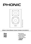
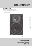
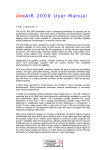
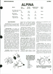
INSTALLATION MANUAL
FOR
ROCKFORD FOSGATE
POWER 360
360
AND
POWER 650
POWER
650
Rockford
Corporation
613 South
Rockford Drive
Tempe
Arizona
85281
(602) 967-3565
INDEX
Introduction . . . . . . . . . . . . . . . . . . . . . . . . . . . . . . . . . . . . . . . . . . . . .
1
Amplifier Features . . . . . . . . . . . . . . . . . . . . . . . . . . . . . . . . . . . . . . .
2
System
Flexibility . . . . . . . . . . . . . . . . . . . . . . . . . . . . . . . . . . . . . . . .
3
Bridging . . . . . . . . . . . . . . . . . . . . . . . . . . . . . . . . . . . . . . .
4
Amplifier Block Diagram . . . . . . . . . . . . . . . . . . . . . . . . . . . . . . . . .
5
Why Biamplify? . . . . . . . . . . . . . . . . . . . . . . . . . . . . . . . . . . . . . . . . .
6
Speaker Impedance . . . . . . . . . . . . . . . . . . . . . . . . . . . . . . . . . . . . .
7
Wire . . . . . . . . . . . . . . . . . . . . . . . . . . . . . . . . . . . . . . . . . . . .
7
Power Ratings . . . . . . . . . . . . . . . . . . . . . . . . . . . . . . . . . . . . . . . . . . .
8
Piezoelectric Tweeters . . . . . . . . . . . . . . . . . . . . . . . . . . . . . . . . . . .
8
Crossover System . . . . . . . . . . . . . . . . . . . . . . . . . . . . . . . . . . . . . . .
9
Using the Crossovers . . . . . . . . . . . . . . . . . . . . . . . . . . . . . . . . . . .
10
Crossover Settings . . . . . . . . . . . . . . . . . . . . . . . . . . . . . . . . . . . . .
11
Crossover Response Curves . . . . . . . . . . . . . . . . . . . . . . . . . . . .
12
Amplifier Power Wiring . . . . . . . . . . . . . . . . . . . . . . . . . . . . . . . . .
13
DIN Interconnect Cable . . . . . . . . . . . . . . . . . . . . . . . . . . . . . . . . .
14
Input Mode Switch . . . . . . . . . . . . . . . . . . . . . . . . . . . . . . . . . . . . .
14
Turn-on
Connection . . . . . . . . . . . . . . . . . . . . . . . . . . . . . . . . . . . .
15
Mounting the 360 . . . . . . . . . . . . . . . . . . . . . . . . . . . . . . . . . . . . . . .
15
Power 650 Specifications . . . . . . . . . . . . . . . . . . . . . . . . . . . . . . .
17
Power 360 Specifications . . . . . . . . . . . . . . . . . . . . . . . . . . . . . . .
18
Biamplified Mode Wiring Diagram . . . . . . . . . . . . . . . . . . . . . . .
19
Power
19
Amplifier
Speaker
6501360
Stereo
Biamplified
Mode
Wiring
Diagram
.
Biamplified Stereo Diagram . . . . . . . . . . . . . . . . . . . . . . . . . . . . .
20
Biamplified Stereo Bridged Mono Woofer Diagram . . . . . . .
21
Dual Stereo Diagram . . . . . . . . . . . . . . . . . . . . . . . . . . . . . . . . . . .
22
Bridged Stereo Diagram . . . . . . . . . . . . . . . . . . . . . . . . . . . . . . . .
23
Bridged Mono Biamplified Diagram . . . . . . . . . . . . . . . . . . . . . .
24
INTRODUCTION
The Power 650 and Power 360 are state-of-the-art 4 channel
power amplifiers for cars, vans, or wherever a 12-volt battery is
available.
The amplifiers are designed to be used with a Rockford-Fosgate
equalizer/pre-amplifier
and any high-quality radio, tape, or
other music source. There are several equalizer/pre-amplifier
units available, including the ZX, and Z, and the 250 preamp.
The Power 650 will provide 325 watts per channel (stereo) and
incorporates a variable-speed fan and shroud assembly for
cooling.
The Power 360 provides 180 watts per channel (stereo) and is
cooled by a finned heatsink.
Both the Power 650 and Power 360 offer exceptional flexibility in
system design. With switchable crossovers and four bridgeable
power amplifier channels, biamplified systems, high-powered
bridged systems, combinations, and four-channel systems are
easy to put together. Both amplifiers are stable into 2-ohm
loads, or 4-ohm loads when bridged.
Protection circuitry in the amplifiers prevent damage due to
shorts, system power problems, or internal failures. They
incorporate internal battery line filtering and extensive noise
prevention circuitry.
The Power 650 and Power 360 are designed to be professionally
installed. The length and nature of your warranty are dramatically
affected if you attempt to install it yourself (See Warranty).
This is because professional installers are experienced with
making your car sound right the first time. Professional
installers make their installations durable because they don’t
want continuing problems and complaints - their reputations
are valuable.
If you want to install your own unit, read this booklet completely
- and Good Luck!
-l-
AMPLIFIER FEATURES
The Power 650 and Power 360 are
have selectable crossovers, four
protection, independently available
rejection circuitry. System wiring
identical.
very similar in design. Both
bridgeable channels, load
bass channels, and noise
for the two amplifiers is
The Power 650’s variable-speed fan-cooling assembly allows it
to run at higher power and into lower-impedance loads than the
Power 360. With four 4-ohm loads, each channel of the Power
650 puts out 125 watts, while the 360 puts out 90. The Power 650
is rated for four 2-ohm loads, at 160 watts each or two 4-ohm
loads in bridged stereo at 325 watts each. The Power 360 is not
rated for 2-ohm loads, and the bridged output is two 8-ohm
loads at 180 watts each.
-2-
SYSTEM FLEXIBILITY
A combination of switched crossovers and four bridgeable
channels in the Power 650 and Power 360 provide unmatched
system flexibility with simple wiring changes. Some of the
possibilities
are:
Biamplified Stereo - A pair of channels drives mid and high
frequency speakers; another pair drives woofers. The crossovers are set to separate the input frequencies into high and
low frequencies for each speaker system.
Biamplified Stereo with Bridged Mono Woofer - Otherwise
similar to the Biamplified stereo system above, this arrangement bridges the two low channels into a single woofer.
Bridged Stereo - Each pair of channels on Left and Right sides
is bridged into a full-range speaker system. The crossovers
are set at Flat position.
Bridged Mono Biamplified -This configuration produces watts
into one mono channel. The high-frequency channel pair is
bridged into midtweeter speaker system and the lowfrequency pair bridged into a woofer. The crossovers are set
to separate woofer and midrange frequencies.
Dual Stereo - With the crossovers set at “Flat” position, the
power amp will act as two separate stereo amplifiers, one
channel pair for rear full range speakers, one for front fullrange 4-ohm speakers. If only one set of speakers can handle
bass frequencies, the “High” crossover can be set to cut off
the front speakers’ low frequency drive.
All of these system configurations are obtained with simple
wiring variations; there are no special “black boxes” to buy and
the system may be modified at any time.
-3-
AMPLIFIER BRIDGING
Operating an amplifier in the “bridged” or “strapped mono”
mode means driving one speaker or speaker system with two
amplifier channels. Each channel will put out full power into its
half of the speaker load, so the system can drive the speaker with
double the power that a single amplifier channel would be
capable of.
When amplifiers are bridged into a single speaker,
amplifier “sees” half of the total speaker impedance.
each
New Rockford-Fosgate amplifiers are designed so that connecting the amplifier for bridged mode is a simple matter of
using the correct speaker leads as shown in the appropriate
system diagram. In these amplifiers, one channel of each pair is
inverted in the amplifier. In normal stereo use, the inverted
channel output is connected to the negative lead of its speaker
load, thus preserving the system’s polarity. In bridged mode, the
inverted channel is connected to the negative lead of the
speaker to be bridged, and the positive lead of the speaker is
connected to the non-inverted channel. This provides the outof-phase drives required for bridged operation.
The Power 650 and Power 360 are designed so that the four
amplifier sections can be bridged in several ways. Right and Left
High-Frequency channels can be bridged, the Right High and
Left Low-Frequency channels can be bridged, the Right High
and Right Low channels can be bridged together, and the Left
High and Left Low channels can be bridged. These combinations allow an unmatched flexibility in designing stereo,
biamplified, and hybrid bridged systems.
The Amplifier Block Diagram shows a simplified diagram of
crossover and amplifier system. In the amplifier blocks,
input shows a “+” for the non-inverted channels and a “-” for
inverted channels. Each “+” channel can be mated to a
channel into a bridged speaker load.
-4-
the
the
the
“-”
DIN
COllfl
INPUTS
RCA
Conn
POWER 650/360
AMPLIFIER BLOCK DIAGRAM
-5-
WHY BIAMPLIFY?
For the performance. Biamplified systems can play cleanly at
higher output levels than stereo systems of the same total
power.
For the convenience. Building a satisfactory crossover system
for woofer-to-midrange crossover frequencies requires large,
expensive inductors and capacitors, as well as design time and
mounting problems. With a biamplified system it’s all done for
you in the active crossover.
Biamplified systems consist of an active (electronic) crossover
system and two stereo amplifiers. The crossover separates the
input signal into low and high-frequency groups and sends each
group of frequencies to a separate amplifier pair. In most
installations, the low-frequency amplifiers drive a pair of
woofers and the high-frequency amplifiers drive a midrangetweeter pair.
In ordinary stereo systems, as the output level increases, the
low-frequency, high-power notes of the music start to drive the
amplifier into clipping. When the bass (drums, rhythm, etc.)
start to overload the amplifier, all higher frequencies are
naturally clipped as well, so midrange distortion is immediately
audible. The harshness and “gargling” effects of clipping are
obnoxious to listen to and may destroy tweeters.
In a well-designed biamplified system, when the low frequencies
start to clip only the low-frequency amplifiers overload. The
high-frequency amplifiers are still reproducing the music
cleanly. Harshness and other overload effects are not heard in
the middle and high frequencies until the high-frequency
amplifiers clip, at a much higher level. The worst effects of the
bass amplifiers’ clipping will usually not be audible, since the
woofers won’t reproduce the high-frequency harmonics of the
clipped drive, and the clean middle and high frequencies cover
the low-frequency blurring and muddiness of the bass.
We have found that, for crossover frequencies up to about 600
Hertz, it is best to use approximately equal power for the low and
high frequency amplifiers of biamplified systems. If the highfrequency amplifiers are significantly lower in power, the highs
will clip before bass distortion is audible, and much of the bass
power capability will be wasted.
-6-
Triamplifying; that is, using another active crossover and stereo
amplifier to run the tweeters only, is technically interesting but
less cost-effective. For one thing, there is little or no masking
effect from the very high frequencies for midrange distortion, so
the biggest performance advantage of multiple-amp systems
isn’t available. Crossover components for passive midrange-totweeter crossovers are reasonably small and inexpensive.
Running a separate tweeter amp system will prevent tweeter
burnout due to heavy midrange clipping, and this is the most
substantial advantage of triamplified systems.
SPEAKER
IMPEDANCE
The Power 650 is designed for a 2-ohm nominal minimum
impedance on each of its four channels. (Two 4-ohm speakers
in parallel form a 2-ohm load.)
The Power 360 is designed for a 4-ohm nominal minimum
impedance on each of its four channels.
In bridged mode (two amplifier channels driving a single load),
each channel “sees” half of the load impedance. Therefore the
Power 650’s minimum load impedance in bridged mode is 4ohms, and the Power 360’s minimum is 8-ohms.
If an output wire from the
impedance drops below safe
into short protection mode. In
off for several seconds every
amplifier shorts, or if the load
minimums, the amplifier will go
“shortstop” the amplifier will turn
time it senses an overload.
SPEAKER WIRE
We recommend that you always use substantial wire for speaker
wiring harnesses. For short runs, 18-Gauge
18-Gaugewirewire is the smallest
we suggest; for runs over 6 feet, at least 16-Gauge
16-Gauge should be
used.
Never allow any speaker wire to touch chassis ground. Many
users find that sound quality is improved by the use of speciallymade heavy-duty speaker wiring from one of several manufacturers. The Power 650 and 360 output harnesses use short
runs of 16-Gauge wire and should not reduce any benefits
gained from specialized speaker wiring.
-7-
SPEAKER
POWER
RATINGS
The Power 650 and 360 are very high-powered amplifiers, and
special care must be taken to be sure that the speakers can
handle the power levels. The speaker manufacturer’s recommendations for power levels and crossover frequencies should
be observed.
Woofers with high power ratings sometimes “pop”, “clang”,
“snap”, or otherwise show signs of bottoming. These speakers
are designed to use the “air spring” of an enclosed box to
prevent bottoming at high power inputs. This applies to most
woofers originally designed for home or professional use. One
solution is to use speakers designed for “infinite baffle” use,
which have very stiff suspensions. The best solution is to build
boxes for the woofers.
As with woofers, midrange drivers’ power capabilities are
determined by voice coil and suspension design. The most
common power-handling problems for mid-ranges arise when
they are crossed over at too low a frequency or with too shallow
a crossover slope. For every doubling of the crossover
frequency, a given midrange driver will handle 20-150% more
system power. The same improvement would result from going
from a 6dB/Octave to a 12dB/Octave crossover.
Tweeters will react the same as midranges to changes in
frequency and slope of their crossovers: the higher the
frequency and the greater the slope, the more power the tweeter
will handle. Tweeter types that are usually above average in
power handling ability include ferrofluid-cooled domes ¾
inches in diameter or larger.
PIEZOELECTRIC
TWEETERS
Piezoelectric tweeters (“piezos”) offer ruggedness, efficiency,
and extended frequency capability. They also often have a
“rough” or “harsh” sound due to large response irregularities
and distortion. They are usually a difficult load for an amplifier.
One characteristic of piezos is that they are a nearly pure
capacitive load. This means that their impedance continuously
decreases with increasing frequency. Unless some means is
used to prevent this continuous decrease, a typical piezo
tweeter’s impedance falls to well under 1 ohm within the
bandwidth of the amplifier. This low capacitive impedance can
upset the amplifier’s compensation scheme and cause ultrasonic (inaudible) oscillations, overheating or damaging the
amplifier.
A simple method of preventing problems is to be sure there is at
least 6 feet of speaker lead between the amplifier and the piezo.
All amplifiers are tested with piezo loads and 6 feet of lead, and
they will have no problem.
Another method of taming the piezo is to insert a 1- to 10-ohm
resistor in series with one of its leads.
CROSSOVER SYSTEM
The Power 650 and Power 360 incorporate separate high- and
low-frequency crossovers, which are controlled by screwdriverslot switches on one end of the power amplifier. The crossover
frequency is set to one of five frequencies or to flat response,
depending on speaker and system characteristics.
The crossover is a two-pole (12 dB/Octave) constant-power
design with a Butterworth transfer characteristic. Outputs are
designed for an accurate phase match between low- and highfrequency outputs (within 5 degrees) to eliminate cancellation
and lobing errors.
High Frequency
Crossover
Position
Frequency
1
Flat
100 Hz
2
3
250 Hz
4
600 Hz
1500 Hz
5
6
4000 Hz
Low Frequency
Crossover
Position
Frequency
1
Flat
2
100 Hz
3
250 Hz
4
600 Hz
5
1500 Hz
6
4000 Hz
-9-
USING
THE
CROSSOVERS
The crossovers are usually used in biamplified mode. They
separate the frequencies in the input signal into low and high
frequencies for the separate woofer and high frequency
amplifiers. (See the Amplifier Block Diagram for a system
layout.) When the crossovers are used for biamplified systems,
the High and Low frequencies are usually set equal.
The most common crossover frequency for biamplified systems
is 250 Hertz. This frequency setting keeps the worst of the lowfrequency power out of the midranges but doesn’t require the
woofers to do a great deal of midrange. For systems whose
midrange speakers cannot handle a lot of power, a 600 Hertz
crossover setting will save the drivers. For systems with
essentially full-range front speakers or very rugged and large
midranges, a 100 Hertz crossover frequency gives better
imaging by putting more midrange energy up front with the
tweeters.
The main use of the 4000 and 15000 Hertz crossover frequencies
is for complex systems which use the amplifier as a midrangetweeter biamplified system. 4000 Hertz is a satisfactory
crossover point for most midrange-tweeter combinations. 1500
Hertz might be used with an extremely rugged tweeter or a small
midrange.
The crossover system can be used to do a certain amount of
equalization for correcting response problems in the car. If the
crossover frequencies in a biamplified system are “underlapped”; that is, the low-frequency crossover is set one notch
lower than the high-frequency crossover, a 6dB dip appears in
the overall “summed” system response. Its frequency is
centered between the low and high crossover settings. If the
crossovers are “overlapped”, the response shows a gradual
peak of about 2 dB, again centered between thecrossover
settings. The “dip” response in particular can improve cars
which have a bad midrange bulge at around 150-200 Hertz, as
often happens. Setting the low crossover at 100 Hertz and the
high crossover at 250 Hertz produces a 6 dB dip at 160 Hertz,
removing tubbiness and unnatural male voices produced by the
car’s resonance. See “Crossover Response Curves” for a graph.
CROSSOVER
SETTINGS
Crossover
Setting, Hz
(Low/High)
Suggested
Applications
Flat/Flat
Dual Stereo systems with two pairs of full range
speaker systems. All Bridged Stereo systems.
Flat/l 00
Dual Stereo systems with front speakers having less
bass capability.
Flat/250
Dual
100/1 00
“Subwoofer” biamplified systems. Large woofers on
low channel, essentially full-range system on high
channel (usually a strong midrange-tweeter pair).
Excellent imaging.
250/250
“Three-way”
biamp systems. W o o f e r s o n l o w
channel, midranges and tweeters on high channel.
Good imaging.
100/250
“Subwoofer” and three-way systems in cars which
have a lower-midrange resonance. Combines
imaging advantages of subwoofer with reduced
midrange power requirements. Excellent imaging.
600/600
“Three-way” biamp systems. As above in 250/250
section, but midrange drivers handle less power.
Fair imaging.
1500/1500
“Three-way” biamp systems having a very light duty
midrange. “ T w o - w a y ” biamp systems with widerange woofers on the low channel and extremely
rugged tweeters on the high channel.
4000/4000
Primarily a midrange-to-tweeter
triamplified systems.
Stereo
systems
-ll-
with
small
front
speakers.
crossover
point
for
Summed Output
Power--Flat
0
Output
dB
-3
-6
-9
-12
-15
63
250
160
400
600
950
Frequency, Hertz
BOTH CROSSOVERS SET EOUAL (250 Hertz)
Outpu
dB
100
63
160
250
Frequency,
400
600
950
Hertz
CROSSOVERS OVERLAPPED (Low 100 Hertz, High 250 Hertz)
Summed Output Power--2 dB Peak
+3 -0,
e--
_#--
L_------
- - _
160
_
---_
250
Frequency,
400
600
950
Hertz
CROSSOVERS OVERLAPPED (Low 250 Hertz, High 100 Hertz)
CROSSOVER RESPONSE CURVES
-12-
AMPLIFIER POWER WIRING
The Power 650 and Power 360 battery power connections are
made with heavy self-resetting wire. A circuit breaker and
connectors are provided with the unit. For best performance
wire the amplifier exactly as described. Any resistive connections or voltage drops in the power wiring will result in
significant power output losses.
White
Power
Wire - This wire goes directly to the circuit
White Power
Wire
breaker mounted near the battery. It is best to use as short a
wire run as feasible: spare crimp connectors for shortened
wires are provided with the unit. Don’t run the power wire near
the interconnect cabling for the preamp: it will induce noise.
Circuit Breaker
Battery
Power
Wire Wire - The circuit breaker
Breakerand
and
Battery
Power
should be mounted in the car engine compartment near the
battery. Connect the “BAT.” terminal of the breaker to the
Positive (+) terminal of the battery using the 1-foot length of
heavy wire provided. Connect the other terminal to the white
power-wire leading to the power amplifier.
Black Ground
Wire
Black
Ground
Wire - Connect this wire directly to a good
chassis ground point. Clean off paint and corrosion around
the ground point to ensure a good connection and bolt the
wire securely to the metal. Be sure that the ground point you
have selected is a piece of chassis metal that is welded to the
main body of the car. (Bare metal should be protected with a
layer of grease or paint to prevent rusting.) DO NOT extend
the ground lead over one foot longer than supplied, since any
voltages developed in the ground lead can appear as hard-tosuppress system noise problems.
Remember that the Power 650 can have peak current demands
well over 100 Amperes. Make any splices secure, never use less
than 10-Gauge wire, and never use longer wire runs than
necessary.
-13-
DIN
INTERCONNECT
CABLE
The 5-pin DIN cable provided connect the Amp to its equalizer/
preamplifier. Run this cable away from the main power wire
(white 10-Gauge) to prevent noise from being coupled into the
cable. Cable color code and pin configuration are given below:
Shield - Ground
- +18 Volts
Red
Black - -18 Volts
White - Right Channel Signal+
Green - Left Channel Signal +
(or yellow)
Ground-
Power Amplifier
Female or pre-out Connector
INPUT MODE SWITCH
The input of the Power 650 and Power 360 normally comes from
the DIN input connector and is split by the crossovers into high
and low channel drives. However, there are some cases where it
is desirable to be able to drive the low channels independently.
For instance, if one wanted to drive the system as two
completely independent stereo amplifiers, one would need to
drive the high channel pair with one stereo signal pair, and the
low channel with another.
The input mode switch (located near the crossover controls on
the units front panel) switches the low channel inputs over the
RCA female connectors. The low-frequency crossover remains
in the circuit and can be used as usual.
-14-
TURN-ON CONNECTION
(Red Wire from 9-Pin Connector)
The Power Amplifier is turned on by applying Positive 12 Volts
to the red wire. Usually, the red wire is connected to source
unit’s “Accessory” or “Auto-Antenna” lead, either of which will
go positive when the source is turned on.
Although the majority of high-quality automotive source units
have an Accessory or Auto-Antenna output, there are many
variations which may require different turn-on methods. If the
source has no Auto-Antenna lead (or if Auto-Antenna goes
down during tape operation):
a. Find the internal switched power voltage inside the source
unit and solder a lead to it. Run the lead out through the
back of the unit (being sure to use a grommet for insulation
from the case) and connect to the amplifier’s red turn-on
b. Or: Install a switch in the car with one terminal connected
to +12 Volts and the other to the amplifier’s red lead.
c. Or: Connect the amplifier’s red lead to the Accessory point
at the car’s fuse block. In this case the amplifier will be
on whenever the car is on. This method will allow the
amplifier to amplify any noise and turn-on and turn-off
transients, and may therefore be unsatisfactory.
MOUNTING THE POWER 650
Since the Power 650 has forced-air cooling rather than relying
on convection, it can be mounted anywhere and in any position
it will fit. The only requirement is that the fan intake and exhaust
are not blocked from fresh air.
MOUNTING THE POWER 360
The mounting position of the Power 360 will have a large effect
on its ability to dissipate the heat generated in normal operation.
The Power 360 has an ample heat sink for its dissipation, and
internal overheating shutoff circuitry, so it is reasonably tolerant
of mounting variations. However, care should be taken to be
sure of adequate cooling.
-15-
Trunk Mounting - We have measured trunk temperatures as
high as 150 degrees Farenheit in the summertime. Since the
thermal shutoff point for the Power 360 is 195 degrees F, it is
easy to see that the amp must be mounted for maximum
cooling capability. Mounting the unit on the floor or top of the
trunk will not allow convection air flow across the fins. Even
better is to mount the unit vertically on a vertical surface, so
upward-flowing air follows thechannels between the heatsink
fins. The Power 360 is too tall for this to usually be practical,
however.
Passenger Compartment Mounting - When the amp is
mounted in the passenger compartment, mounting requirements are considerably relaxed, since the driver will not often
allow temperatures to stay anywhere near 150 degrees F.
Floor mounting is usually satisfactory in the cab, and under
the seat will work as long as there is at least 1 inch above the
amplifier fins for air movement. Vertical mounting (for
instance, the back of pickup cabs) is still the best.
Any situation which allows moving air to be directed over the
cooling fins will improve cooling dramatically. A simple fan
playing on the amplifier will improve cooling by a factor of 3.
There are situations where it is feasible to direct some of the
car’s refrigeration air over the amplifier. In any case it is critical
that the amp not be enclosed in a box or covered so that air can’t
flow.
-16-
POWER 650 SPECIFICATIONS
Power Ratings: 4 Channel
4 Ohms: 125 watts per channel
Ohms, 4 channels driven,
less than 0.05% THD +
& Noise).
2 Ohms: 160 watts per channel
Ohms, 4 channels driven,
less than 0.1% THD + N.
continuous power into 4
from 20 to 20,000Hz, with
N (Total Harmonic Distortion
continuous power into 2
from 20 to 20,000Hz, with
Power Ratings: 2 Channel (bridged)
4 Ohms: 325 watts per channel continuous power into 4
Ohms, 2 channels driven, from 20 to 20,000Hz, with
less than 0.05% THD + N.
± .5dB.
Frequency Response: 20 to 20,000Hz,
Bandwidth: 15 to 20,000Hz, ± 3dB.
Damping Factor: greater than 200 at 50Hz.
Slew Factor: greater than 2.5.
Slew Rate: greater than 10 volts per microsecond.
Crossovers:
slope is 12dB per octave.
adjustable positions are: flat, 100Hz, 250Hz,
4KHz.
600Hz, 1.5Hz, and
Protection
The Punch possesses the ability to sense shorts in installation
wiring and will not allow the amplifier to be damaged.
The Punch also employs thermal switches which protect the
amplifier from overheating damage.
Fuses are provided for speakers which are directly connected
with no crossover components.
Dimensions
18 3/1 0” long x 8 1/10” wide x 2% high, exclusive of knobs and
wiring.
19 3/10” long x 8 1/10” wide x 2%” high, minimum mounting
requirements.
Note:
Achieving ultimate performance from Rockford Fosgate
products is our main concern. Therefore research and
development of a new product doesn’t end when it
finally reaches production. For this reason Rockford’s
specifications are subject to change without notice.
- 17 -
POWER 360 SPECIFICATIONS
Power:
Four channels at 90 Watts/Channel continuous, all channels
driven into 4 Ohms, 20Hz - 20KHz, with less than .03% THD +
Noise.
Noise:
Less than -8OdB
both power amp and preamp.
Crossover:
12dB/Octave, switch controlled.
Crossover Frequencies:
Flat
1 OOHz
250Hz
600Hz
1500Hz
4000Hz
Preamp
Sensitivity:
50Mv to 2.5V adjustable.
Preamp Frequency Response:
20-Hz-20KHz + .dB.
-18-
POSITIVE-VOLTAGE TURN-ON
TO SOURCE ACCESSORY OR
AUTO-ANTENNA LEAD
RED
LEFT HIGH CHAN.
MID-TWEETER
INTERCONNECT CABLE
TO EQUALIZER/
PREAMPLIFIER
RIGHT HIGH CHAN.
MID-TWEETER
%
u 5-PIN DIN
CONNECTOR
I
1
9-PIN
CONNECTOR
LEFT LOW CHAN.
J WOOFER
RIGHT LOW CHAN.
POWER AMP
WOOFER
BLACK
8 -GAUGE
/ TO CHASSIS GROUND
WHITE
8 -GAUGE-TO
CIRCUIT
BATTERY
BREAKER
POWER 650/360
STEREO BIAMPLIFIED MODE
HIGH AND LOW CROSSOVERS SET TO SAME FREQUENCY
-19-
Midrange/
Tweeters
Woofers
Left High
Channe l
Left Low
Channel
Right Low
Channel
P o w e r 650 I P o w e r 360
9-Pin
Connector
Notes : High and Low crossovers set to 100, 250, or 600 Hertz
BIAMPLIFIED
- 20 -
STEREO
Right High
Channel
o
Midrange/
Tweeters
l
0
Left High
Channe 1
Low
Channe 1
Low
Channel
Right
High
Channel
Power 650 / Power 360
9-Pin Connector
Notes : Both
High and Low Crossovers set to 100,
250,
or 600
Hertz
BIAMPLIFIED STEREO
BRIDGED MONO WOOFER
2 1
I
Full-Range
Or
Midrange/
Tweeters
Left
High
Channel
Left
Low
Channel
Right Low
Channel
Right High
Channel
Power 650/ Power 360
9-Pin C o n n e c t o r
Notes:
Low c r o s s o v e r s e t t o “Flat”.
H i g h c r o s s o v e r s e t t o “ F l a t ” f o r full-range f r o n t s p e a k e r
1 0 0 o r 2 5 0 Hertz f o r Midrange/Tweeter f r o n t s y s t e m .
Note t h a t low c h a n n e l c o l o r c o d e s a r e r e v e r s e d
biamplified
systems.
from
DUAL STEREO
w/Bridged Woofers
-22-
svstem.
those o f
Full-Range
Left
Right
Channel
Channel
Power 650 / Power 360
9-Pin Connector
Notes : Both High and Lou Crossovers set to “Flat” position.
BRIDGED STEREO
- 23 -
-4 O
Midrange/
Tweeters
Woofers
c
-
al
2
I
High
High
Channel
Channel
I c’
L
Power 650 / Power 360 #1
9-Pin Connector
Low
Channel
i
Channel
Power 650 / Power 360
I
#2
9-Pin Connector
I
Notes : High and lou crossovers set to 100, 250 or 600 Hertz.
Bridging “Y” Adapter, P/N FA-683,
Right
channels
See “Schematic,
wiring
to
separate
Bridged
is used to
amplifiers.
Kono Biamplified
split out Left and
Mode” for complete system
diagram.
BRIDGED MONO BIAMPLIFIED
-24 -