1
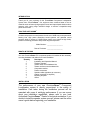
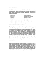
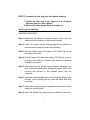
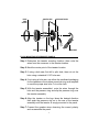
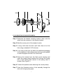
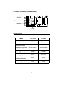
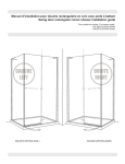
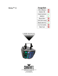
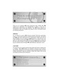
PowerClass®
COMPONENT SPEAKER SYSTEM
INTRODUCTION
Thank you for your purchase of this PowerClass® Component Loudspeaker
System from PrecisionPower™. Our engineers have combined state of the art
materials such as foamed prolypropylene cones and vapor-deposit titanium dome
tweeters with cutting edge industrial design to achieve competition-ready
performance levels.
PRACTICE SAFE SOUND™
Continuous exposure to sound pressure levels over 100dB may cause permanent
hearing loss. High power automotive sound systems can generate sound
pressure levels in excess of 130dB. When playing your system at high levels,
please use hearing protection and prevent long term exposure.
Model Number: ___________________
Date of Purchase: ___________________
WHAT’S IN THE BOX
Your new PrecisionPower™ PC component speaker kit includes all the necessary
mounting hardware and cables for a basic installation:
Quantity
Description
1
Installation and Operation Manual
2
Titanium Tweeters
2
Tweeter flush mount hardware kits
2
Tweeter surface mount hardware kits
2
Component woofers
2
Passive crossovers
4
Speaker cables (speakers to crossover)
4
Cables (crossover to amplifier)
1
Mounting template
2
Grilles
INSTALLATION
The performance of your new PrecisionPowerTM Component
Loudspeaker system is directly proportional to the quality of
installation. Care taken during the installation process will be
rewarded with years of satisfying performance. If you are unsure
about your installation capabilities, please refer to your local
Authorized PrecisionPowerTM Dealer for technical assistance. If you
decide to install the speaker system yourself, please read the entire
owner’s guide before beginning your installation.
1
TOOLS OF THE TRADE
Listed below are tools you may wish to have on hand before starting
your installation. Having the proper tools will make the installation
much easier. Some of these tools are necessities, some will just
make the job easier.
•
•
•
•
•
•
•
•
•
Marking Pen
Electric Drill
1/4" Drill Bit
1/8" Drill Bit
3/8" Drill Bit
Hole Saw Arbor
4¾" Hole Saw (5¼” woofer install.)
5¾" Hole Saw (6½" woofer install.)
1¾" Hole Saw (for flush mount tweeter
• Phillips Screwdriver
• Volt/Ohm Meter (Optional)
• Assorted Tin Snips
• Wire Cutters
• Wire Crimpers
• Wire Strippers
• Razor Knife (Optional)
install.)
FINDING SPEAKER MOUNTING LOCATIONS
Choosing the correct speaker locations can have a significant effect
on the sound quality of the system. There are many different
considerations for choosing the locations that best suit your needs.
The locations must be large enough for the speakers to fit without
interfering with other vehicle parts such as window mechanisms,
etc. Care is needed to ensure that the location you have chosen will
not affect any of the mechanical or electrical operations of the
vehicle. If minimal intrusion in your vehicle is desired, factory
speaker locations may be the ticket for you. Placing the speaker in
the factory location can often give you very desirable results.
Alternative locations to consider include mounting in customized
kick panels, rear decks, or side panels.
DOOR MOUNTING
When considering possible speaker locations in the doors, be sure to
check the operation of the window mechanism and all other moving
parts inside the door. Most vehicles use a stabilizer stop bar in
between the door and the door jamb. This bar prevents the door from
opening too far, but may intrude into the speaker mounting area
when the door is closed. Many do-it-yourself installers overlook this
and check for speaker clearance only when the door is fully open.
2
REAR DECK MOUNTING
In rear deck installations, check the operation of the trunk
suspension springs or tension bars. These tension bars can move
when opening and closing the trunk and can exert a great deal of
force against anything that obstructs their movement, such as a
speaker basket or motor assembly. In addition, try to avoid locating
the speakers too close to the back edge of the rear deck. Installing
the rearmost screws may not be possible without the removal of the
rear window.
INSTALLING THE MIDRANGE
Step 1: Determine where the speaker will be mounted. Make sure
there is a flat area large enough for the speaker to fit
properly. An uneven mounting surface can damage the
driver and limit the bass performance of your PC
component system.
Step 2: Check to make sure the mounting location you have chosen
for the speaker will not interfere with the operation of the
vehicle.
Step 3: Using the supplied template guide, mark the hole with a pen.
Step 4: [Skip this step if using correctly sized factory locations] Cut
the hole for the speaker. A hole can be cut either with a
pair of metal tin snips, an air or jig saw, or with a hole saw
corresponding to the size of the woofer listed below.
• 4¾” Hole Saw (5¼” woofer installation)
• 5¾” Hole Saw (6½” woofer installation)
WARNING: Window mechanisms and electrical wires and other
expensive car parts have a nasty habit of hiding where you
least expect. CHECK BEFORE YOU DRILL!
Step 5: Run the speaker wire to the speakers. Make sure to keep
wires away from sharp metal or other edges. When passing
through metal, use a protective grommet.
3
Step 6: Using the plastic grille ring as a template, mark the
mounting holes with a pen.
Step 7: Pre-drill mounting holes using a 1/8" drill bit.
WARNING: Window mechanisms and electrical wires and other
expensive car parts have a nasty habit of hiding where you
least expect. CHECK BEFORE YOU DRILL!
Step 8: Pull the wire through the speaker opening and connect to
the speaker. Be sure to observe proper midrange polarity
during this process.
Step 9: To mount the speaker, the speaker is placed through the
grille ring from the front. Place the speaker and the grille
ring in the installation hole. Align the mounting screw holes
and drive in the four mounting screws. Push the perforated
metal grille back into the grille ring, using the supplied black
butyl material to secure it.
GRILL INSERT
#8 1-1/4”
SHEET METAL SCREWS
SPEAKER
GRILL RING
MOUNTING PANEL
4
NOTE: To remove the trim ring from the tweeter housing:
1. Rotate the trim ring a few degrees in a clockwise
direction until you feel a detent.
2. Remove the trim ring by lifting it straight up.
INSTALLING THE TWEETER
SURFACE MOUNTING
Step 1: Determine the tweeter mounting location, then route the
wires from the crossover to the tweeter location.
Step 2: Place the surface mount housing against the panel and
mark the two holes at the rear of the housing.
Step 3: Drill the smaller center hole using a 1/8" drill bit. This is the
mounting screw hole.
Step 4: Drill the larger off-center hole using a 3/8" drill bit, insert a
grommet and route the speaker wire from the crossover
through the grommet.
Step 5: After removing the surface mount tweeter assembly trim
ring, route the tweeter wires through the larger hole in the
housing and connect to the speaker wires from the
crossover.
Step 6: Insert the excess speaker wire into the hole and position the
housing so the housing will not pinch the wires after final
mounting.
Step 7: Attach the housing using the supplied screws of the correct
length for a solid mount.
Step 8: Insert the tweeter into the housing and attach the trim ring.
5
MOUNTING SCREWS
SURFACE
MOUNT
TRIM RING
TWEETER
SURFACE MOUNT HOUSING
PANEL
TWEETER WIRE
WIRING HARNESS
FLUSH MOUNTING INTO REMOVED PANELS
Step 1: Determine the tweeter mounting location, then route the
wires from the crossover to the tweeter location.
Step 2: Mark the center point of the tweeter location.
Step 3: If using a hole saw, first drill a pilot hole, then cut out the
hole using a standard 2-1/8" hole saw.
Step 4: If not using a hole saw, use either the cardboard packaging
for the tweeters or the surface mount trim ring as a template
to mark the proper size hole. Cut out the hole.
Step 5: With the tweeter assembled, route the wires through the
hole and the pressure ring and slip the pressure ring over
the tweeter assembly.
Step 6: Align the tweeter so the logo faces the desired direction
then push the pressure ring on to the rear of the tweeter
assembly until the tweeter is snugly mounted to the panel.
Step 7: Connect the speaker wires observing the correct polarity
and re-assemble the panel.
6
TRIM RING
FLUSH MOUNT
HOUSING
TWEETER WIRE
WIRING HARNESS
FLUSH MOUNTING INTO MOUNTED PANELS
Step 1: Determine the tweeter mounting location, then route the
wires from the crossover to the tweeter location.
Step 2: Mark the center point of the tweeter location.
Step 3: If using a hole saw, first drill a pilot hole, then cut out the
hole using a standard 2-1/8" hole saw.
Step 4: If not using a hole saw, use either the cardboard packaging
for the tweeters or the surface mount trim ring as a template
to mark the proper size hole. Cut out the hole.
Step 5: Remove the tweeter from the flush mount housing and
insert the proper length machine bolt through the center
hole of the housing and connect to the spring steel Xbracket. (See Figure 3.)
Step 6: Connect the speaker wires observing the correct polarity.
Step 7: Press the X-bracket portion of the assembly through the
hole until its legs spring open.
7
Step 8: Screw the bolts in until the tweeter housing is firmly
mounted to the panel. (Make sure the arrow at the rear of
the tweeter housing is pointing in the desired direction.)
Step 9: Insert the tweeter into the housing and attach trim ring.
INSTALLING THE CROSSOVER
Step 1: Find a location for the crossover away from any factory or
aftermarket electrical wires. It is recommended to mount the
passive crossover close to the amplifier. In the event you
decide to upgrade and biamplify the system, mounting the
passive crossover close to the amplifier would simplify the
installation upgrade.
Step 2: Remove top cover of crossover housing. Don’t lose it.
Step 3: Mark the mounting holes with a marking pen.
Step 4: Remove crossover and pre-drill mounting holes using a 1/8”
drill bit.
WARNING: Window mechanisms, electrical wires, and other
expensive car parts have a nasty habit of hiding where you
least expect. CHECK BEFORE YOU DRILL!
Step 5: Mount the crossover using the supplied #8 screws.
Step 6: Connect the wires. Make sure the speaker wires for the
midrange go to the woofer output and the tweeter to the
tweeter output. Be sure to observe the correct polarity.
Changing the polarity of the tweeter may be necessary for
optimum sound quality. Use the tweeter level adjustment
switch to set the output levels of the tweeters to your liking.
Step 7: Re-install the crossover cover.
8
PC PASSIVE CROSSOVER (COVER REMOVED)
Woofer
To amplifier
Tweeter
0 -3
0,-3dB
level switch
SPECIFICATIONS
Model
PC 525S
PC 650S
4 ohms
4 ohms
Power
Continuous/Peak
50/100 watts
60/120 watts
Frequency Response
90 Hz–20kHz
90 Hz–20kHz
92 db
92 db
2-7/8”
2-15/16”
4-3/4”
5-3/4”
1-3/4”
1-3/4”
Nominal Impedance
Sensitivity
(2.83v @ 1w/1m)
Woofer
Mounting Depth
Woofer
Mounting Diameter
Tweeter
Mounting Diameter
9
Warranty
LIMITED TWO YEAR CONSUMER WARRANTY:
Directed Electronics, Inc. promises to the original purchaser, to replace this product should
it prove to be defective in workmanship or material under normal use, for a period of two
years from the date of purchase from the dealer as indicated by the date code marking of
the product PROVIDED the product was installed by an authorized Directed dealer. During
this two-year period, there will be no charge for this replacement PROVIDED the unit is
returned to Directed, shipping pre-paid. If the unit is installed by anyone other than an
authorized Directed dealer, the warranty period will be one year from the date of purchase
by the dealer as indicated by the date code marking of the product. This warranty is nontransferable and does not apply to any unit that has been modified or used in a manner
contrary to its intended purpose, and does not cover damage to the unit caused by
installation or removal of the unit. During this one-year period, there will be no charge for
this replacement PROVIDED the unit is returned to Directed, shipping pre-paid. This
warranty is void if the product has been damaged by accident or unreasonable use,
neglect, improper service or other causes not arising out of defects in materials or
construction. Units which are found to be damaged by abuse resulting in thermally
damaged voice coils are not covered by this warranty but may be replaced at the
absolute/sole discretion of Directed. ALL WARRANTIES INCLUDING BUT NOT LIMITED
TO
EXPRESS
WARRANTY,
IMPLIED
WARRANTY,
WARRANTY
OF
MERCHANTABILITY, FITNESS FOR PARTICULAR PURPOSE, AND WARRANTY OF
NON-INFRINGEMENT OF INTELLECTUAL PROPERTY ARE EXPRESSLY EXCLUDED
TO THE MAXIMUM EXTENT ALLOWED BY LAW, AND DIRECTED NEITHER
ASSUMES NOR AUTHORIZES ANY PERSON TO ASSUME FOR IT ANY LIABILITY IN
CONNECTION WITH THE SALE OF THE PRODUCT. DIRECTED HAS ABSOLUTELY
NO LIABILITY FOR ANY AND ALL ACTS OF THIRD PARTIES INCLUDING ITS
AUTHORIZED DEALERS OR INSTALLERS. Unit must be returned to Directed, postage
pre-paid, with bill of sale or other dated proof of purchase bearing the following information:
consumer's name, telephone number, and address, authorized dealer's name and
address, and product description. Note: This warranty does not cover labor costs for the
removal and reinstallation of the unit. IN ORDER FOR THIS WARRANTY TO BE VALID,
YOUR UNIT MUST BE SHIPPED WITH PROOF OF INSTALLATION BY AN
AUTHORIZED DIRECTED DEALER. ALL UNITS RECEIVED BY DIRECTED FOR
WARRANTY REPAIR WITHOUT PROOF OF DIRECTED DEALER INSTALLATION WILL
BE COVERED BY THE LIMITED 1 YEAR PARTS AND LABOR WARRANTY. Note: This
warranty does not cover labor costs for the removal and reinstallation of the unit. BY
PURCHASING THIS PRODUCT, THE CONSUMER AGREES AND CONSENTS THAT
ALL DISPUTES BETWEEN THE CONSUMER AND DIRECTED SHALL BE RESOLVED
IN ACCORDANCE WITH CALIFORNIA LAWS IN SAN DIEGO COUNTY, CALIFORNIA.
© 2003 Directed Electronics, Inc. All rights reserved. G38106/11 12-03