1
ESPRIT 748 ES
Ma
U
de in
C
A
AN D
A
LISTED
Installation Manual
VERSION 3.10
P
48ESEI-03
R
E
C
U
R
D
I
T
Y
S
O
Y
S
T
X
E
M
S
1989
R
A
D
10
NN
A
S
A
O
th
IV E R SA
R
X
1999
Y
P
IM748ES
Requirements and guidelines for U.L. INSTALLATIONS
UL listed in accordance with standard UL1023 (Household Burglar - Alarm System
Units), standard UL985 (Household Fire Warning Units) and UL1635 (Digital Alarm
Communicator System Units).
UL has only evaluated the 708, 728, 728 EXPRESS, 738, 738 EXPRESS, 748 and
748ES for compatibility with the Ademco model 685, FBI model CP220FB, SURGUARD SG-MLR2-D6 and Silent Knight model 9000.
Look for the
mark on product. Only products bearing this mark are UL listed.
Some operational features are not permitted in UL installations. To respect the standards for household applications, the installer should follow these guidelines when configuring the system.
1. ALL components of the system should be UL listed for the intended application.
2. If the installation is a FIRE ALARM application, refer to NFPA Standard 74 for details
on locating smoke detectors. There must be at least one UL-Listed Indoor Fire Alarm
Warning Signaling Appliance.
3. For U.L. Burglar Applications:
Maximum entry time = 45 seconds
Maximum exit time = 60 seconds
Minimum bell cutoff time = 4 minutes
4. Models 629, 633, 639, are not UL listed.
5. The upload/download software should not be used on UL listed systems.
Requirements and Guidelines for AUSTEL INSTALLATIONS
Austel-approved installations: use a transformer approved by the State Electricity commission, such as "Dyen" PA series 15VAC 22VA. With this transformer, do not exceed the
following maximum currents: - maximum Auxiliary current (including keypads): 300mA
- maximum Bell current :600mA
Requirements and Guidelines for ULC INSTALLATIONS
When the system controls a fire alarm system, wiring method must correspond to
section 32 of the Canadian Electrical Code.
Look for the
mark on product. Only products bearing this mark are ULC listed.
!
IM748ES
TABLE OF CONTENTS
REQUIREMENTS/GUIDELINES FOR UL, ULC AND AUSTEL INSTALLATIONS
INTRODUCTION . . . . . . . . . . . . . . . . . . . . . . . . . . . . . . . . . . . . . . . . . . . . . . .
ABOUT PARADOX . . . . . . . . . . . . . . . . . . . . . . . . . . . . . . . . . . . . . . . . . . . . . . . . . .
ABOUT THIS MANUAL . . . . . . . . . . . . . . . . . . . . . . . . . . . . . . . . . . . . . . . . . . . . . .
FEATURES . . . . . . . . . . . . . . . . . . . . . . . . . . . . . . . . . . . . . . . . . . . . . . . . . . .
Reliability . . . . . . . . . . . . . . . . . . . . . . . . . . . . . . . . . . . . . . . . . . . . . . . . .
Total compatibility . . . . . . . . . . . . . . . . . . . . . . . . . . . . . . . . . . . . . . . . . .
User-Friendly Operation . . . . . . . . . . . . . . . . . . . . . . . . . . . . . . . . . . . . .
False Alarm Prevention . . . . . . . . . . . . . . . . . . . . . . . . . . . . . . . . . . . . .
Flexible System Partitioning . . . . . . . . . . . . . . . . . . . . . . . . . . . . . . . . .
High-Speed Preprogrammed Communication . . . . . . . . . . . . . . . . . . .
Event Buffer and “Real Time Clock” . . . . . . . . . . . . . . . . . . . . . . . . . . .
Programmable Outputs . . . . . . . . . . . . . . . . . . . . . . . . . . . . . . . . . . . . .
Espload Upload/Download Software . . . . . . . . . . . . . . . . . . . . . . . . . . .
SPECIFICATIONS . . . . . . . . . . . . . . . . . . . . . . . . . . . . . . . . . . . . . . . . . . . .
Inputs and Outputs . . . . . . . . . . . . . . . . . . . . . . . . . . . . . . . . . . . . . . . . .
Event Buffer . . . . . . . . . . . . . . . . . . . . . . . . . . . . . . . . . . . . . . . . . . . . . . .
Operating Modes . . . . . . . . . . . . . . . . . . . . . . . . . . . . . . . . . . . . . . . . . . .
Digital Communicator . . . . . . . . . . . . . . . . . . . . . . . . . . . . . . . . . . . . . . .
Espload . . . . . . . . . . . . . . . . . . . . . . . . . . . . . . . . . . . . . . . . . . . . . . . . . .
Accessory Modules . . . . . . . . . . . . . . . . . . . . . . . . . . . . . . . . . . . . . . . . .
Keypads . . . . . . . . . . . . . . . . . . . . . . . . . . . . . . . . . . . . . . . . . . . . . . . . . .
Current Consumption . . . . . . . . . . . . . . . . . . . . . . . . . . . . . . . . . . . . . . .
I
BASIC INSTALLATION . . . . . . . . . . . . . . . . . . . . . . . . . . . . . . . . . . . . . . .
6-11
6
7
7
7
7
7
8
8
8-9
9
10
10
10
10
10
11
LOCATION AND MOUNTING . . . . . . . . . . . . . . . . . . . . . . . . . . . . . . . . . . . . .
EARTH GROUND . . . . . . . . . . . . . . . . . . . . . . . . . . . . . . . . . . . . . . . . . . . . . . .
AC . . . . . . . . . . . . . . . . . . . . . . . . . . . . . . . . . . . . . . . . . . . . . . . . . . . . . . . . . . .
PROGRAMMABLE OUTPUTS . . . . . . . . . . . . . . . . . . . . . . . . . . . . . . . . . . . . .
BELL/SIREN OUTPUT . . . . . . . . . . . . . . . . . . . . . . . . . . . . . . . . . . . . . . . . . . .
AUXILIARY POWER TERMINALS . . . . . . . . . . . . . . . . . . . . . . . . . . . . . . . . .
KEYPAD CONNECTIONS . . . . . . . . . . . . . . . . . . . . . . . . . . . . . . . . . . . . . . . .
ZONE INPUT TERMINALS . . . . . . . . . . . . . . . . . . . . . . . . . . . . . . . . . . . . . . . .
Single zone connections . . . . . . . . . . . . . . . . . . . . . . . . . . . . . . . . . . . . .
TAMPER/WIRE FAULT DEFINITIONS AND OPTIONS . . . . . . . . . . . . . . . . .
FIRE CIRCUIT . . . . . . . . . . . . . . . . . . . . . . . . . . . . . . . . . . . . . . . . . . . . . . . . . .
TELEPHONE LINE CONNECTION . . . . . . . . . . . . . . . . . . . . . . . . . . . . . . . . .
POWERING-UP THE UNIT . . . . . . . . . . . . . . . . . . . . . . . . . . . . . . . . . . . . . . . .
Panel Programming Methods . . . . . . . . . . . . . . . . . . . . . . . . . . . . . . . .
Battery Hook-Up . . . . . . . . . . . . . . . . . . . . . . . . . . . . . . . . . . . . . . . . . . .
Battery Test . . . . . . . . . . . . . . . . . . . . . . . . . . . . . . . . . . . . . . . . . . . . . . .
INSTALLER PROGRAMMING . . . . . . . . . . . . . . . . . . . . . . . . . . . . . . . .
ESPLOAD . . . . . . . . . . . . . . . . . . . . . . . . . . . . . . . . . . . . . . . . . . . . . . . . . . . . .
KEYPAD . . . . . . . . . . . . . . . . . . . . . . . . . . . . . . . . . . . . . . . . . . . . . . . . . . . . . .
PROGRAMMABLE FEATURES . . . . . . . . . . . . . . . . . . . . . . . . . . . . . . . . . . .
Hexa programming . . . . . . . . . . . . . . . . . . . . . . . . . . . . . . . . . . . . . . . . .
Streamlined section programming . . . . . . . . . . . . . . . . . . . . . . . . . . . .
Installer Code . . . . . . . . . . . . . . . . . . . . . . . . . . . . . . . . . . . . . . . . . . . . .
Panel answer options . . . . . . . . . . . . . . . . . . . . . . . . . . . . . . . . . . . . . . .
Panel Identifier . . . . . . . . . . . . . . . . . . . . . . . . . . . . . . . . . . . . . . . . . . . . .
PC Password . . . . . . . . . . . . . . . . . . . . . . . . . . . . . . . . . . . . . . . . . . . . . .
Telephone and Account Numbers . . . . . . . . . . . . . . . . . . . . . . . . . . . .
Computer telephone number . . . . . . . . . . . . . . . . . . . . . . . . . . . . .
Central station telephone numbers . . . . . . . . . . . . . . . . . . . . . . .
System account codes . . . . . . . . . . . . . . . . . . . . . . . . . . . . . . . . . .
Time correction . . . . . . . . . . . . . . . . . . . . . . . . . . . . . . . . . . . . . . . . . . . .
Communicator Formats . . . . . . . . . . . . . . . . . . . . . . . . . . . . . . . . . . . . .
1
4-6
4
4
4
4
4
4
4
4
4
5
5
5
5-6
5
5
5
6
6
6
6
6
11-23
11
11
11
11
11
11
12
12
12
12-13
12
12
13
13
13-14
IM748ES
TABLE OF CONTENTS (continued)
Programmable Output (PGM) Types . . . . . . . . . . . . . . . . . . . . . . . . . . .
Typical PGM Programming . . . . . . . . . . . . . . . . . . . . . . . . . . . . . . . . . .
Special Timing Functions . . . . . . . . . . . . . . . . . . . . . . . . . . . . . . . . . . . .
3 digit decimal value programming . . . . . . . . . . . . . . . . . . . . . . . .
"No movement" . . . . . . . . . . . . . . . . . . . . . . . . . . . . . . . . . . . . . . .
"Late to close" . . . . . . . . . . . . . . . . . . . . . . . . . . . . . . . . . . . . . . . . .
Auto arming . . . . . . . . . . . . . . . . . . . . . . . . . . . . . . . . . . . . . . . . . . .
Operational note regarding special timing functions . . . . . . . . .
Auto arm/report options . . . . . . . . . . . . . . . . . . . . . . . . . . . . . . . . .
Auto arm options . . . . . . . . . . . . . . . . . . . . . . . . . . . . . . . . . . . . . . .
Exit Delay . . . . . . . . . . . . . . . . . . . . . . . . . . . . . . . . . . . . . . . . . . . . .
Entry delay 1 . . . . . . . . . . . . . . . . . . . . . . . . . . . . . . . . . . . . . . . . . .
Entry delay 2 . . . . . . . . . . . . . . . . . . . . . . . . . . . . . . . . . . . . . . . . . .
Bell cut-off time . . . . . . . . . . . . . . . . . . . . . . . . . . . . . . . . . . . . . . . .
Zone speed . . . . . . . . . . . . . . . . . . . . . . . . . . . . . . . . . . . . . . . . . . .
Power failure report delay . . . . . . . . . . . . . . . . . . . . . . . . . . . . . . .
“No movement” report time . . . . . . . . . . . . . . . . . . . . . . . . . . . . . .
PGM timer setting. . . . . . . . . . . . . . . . . . . . . . . . . . . . . . . . . . . . . . .
Intellizone delay . . . . . . . . . . . . . . . . . . . . . . . . . . . . . . . . . . . . . . .
Installer Lock . . . . . . . . . . . . . . . . . . . . . . . . . . . . . . . . . . . . . . . . .
Programmable delay before alarm transmission . . . . . . . . . . . . .
Recent closing delay . . . . . . . . . . . . . . . . . . . . . . . . . . . . . . . . . . .
System Options . . . . . . . . . . . . . . . . . . . . . . . . . . . . . . . . . . . . . . . . . . .
Feature select programming . . . . . . . . . . . . . . . . . . . . . . . . . . . . .
Code priority . . . . . . . . . . . . . . . . . . . . . . . . . . . . . . . . . . . . . . . . . .
TLM options . . . . . . . . . . . . . . . . . . . . . . . . . . . . . . . . . . . . . . . . . . .
Arming using PS1 keyswitch . . . . . . . . . . . . . . . . . . . . . . . . . . . . .
Call back . . . . . . . . . . . . . . . . . . . . . . . . . . . . . . . . . . . . . . . . . . . . .
Auto arm . . . . . . . . . . . . . . . . . . . . . . . . . . . . . . . . . . . . . . . . . . . . .
Touch tone options . . . . . . . . . . . . . . . . . . . . . . . . . . . . . . . . . . . .
Partitioning . . . . . . . . . . . . . . . . . . . . . . . . . . . . . . . . . . . . . . . . . . .
Silent alarm . . . . . . . . . . . . . . . . . . . . . . . . . . . . . . . . . . . . . . . . . . .
Dialing pulse rates . . . . . . . . . . . . . . . . . . . . . . . . . . . . . . . . . . . . .
Reporting options . . . . . . . . . . . . . . . . . . . . . . . . . . . . . . . . . . . . .
Bell squawk . . . . . . . . . . . . . . . . . . . . . . . . . . . . . . . . . . . . . . . . . . .
Auto zone shutdown . . . . . . . . . . . . . . . . . . . . . . . . . . . . . . . . . . . .
Automatic event buffer transmission . . . . . . . . . . . . . . . . . . . . . .
Enable keypad panic signals . . . . . . . . . . . . . . . . . . . . . . . . . . . . .
Keypad panic options . . . . . . . . . . . . . . . . . . . . . . . . . . . . . . . . . . .
"One key" arming enable . . . . . . . . . . . . . . . . . . . . . . . . . . . . . . . .
User/access code length . . . . . . . . . . . . . . . . . . . . . . . . . . . . . . . .
Tamper/wire fault definitions . . . . . . . . . . . . . . . . . . . . . . . . . . . .
Beep on exit delay . . . . . . . . . . . . . . . . . . . . . . . . . . . . . . . . . . . . .
Zone restore transmission . . . . . . . . . . . . . . . . . . . . . . . . . . . . . . .
Zones with EOL resistors . . . . . . . . . . . . . . . . . . . . . . . . . . . . . . . .
Always report disarm . . . . . . . . . . . . . . . . . . . . . . . . . . . . . . . . . . .
Exclude power failure from trouble display . . . . . . . . . . . . . . . . .
Arming Options . . . . . . . . . . . . . . . . . . . . . . . . . . . . . . . . . . . . . . . . . . . .
Auto arm . . . . . . . . . . . . . . . . . . . . . . . . . . . . . . . . . . . . . . . . . . . . . .
No tamper bypass . . . . . . . . . . . . . . . . . . . . . . . . . . . . . . . . . . . . .
Audible trouble warning . . . . . . . . . . . . . . . . . . . . . . . . . . . . . . . . .
Keypad zone supervision . . . . . . . . . . . . . . . . . . . . . . . . . . . . . . . .
Zone Definition . . . . . . . . . . . . . . . . . . . . . . . . . . . . . . . . . . . . . . . . . . . .
Intellizone definition . . . . . . . . . . . . . . . . . . . . . . . . . . . . . . . . . . . .
Silent/audible . . . . . . . . . . . . . . . . . . . . . . . . . . . . . . . . . . . . . . . . . .
24 hour - fire/regular . . . . . . . . . . . . . . . . . . . . . . . . . . . . . . . . . . . .
Instant . . . . . . . . . . . . . . . . . . . . . . . . . . . . . . . . . . . . . . . . . . . . . . .
2
14
15
15-17
15
15
15
15
16
16
16
16
16
16
16
16
16
16
17
17
17
17
17
17-20
17
17
17
18
18
18
18
18
18
18
18-19
19
19
19-20
20
20
20
20
20
20
20
20
20
20
21
21
21
21
21
21-22
21
21
22
22
IM748ES
TABLE OF CONTENTS (continued)
Follow . . . . . . . . . . . . . . . . . . . . . . . . . . . . . . . . . . . . . . . . . . . . . . . .
Delay 2 . . . . . . . . . . . . . . . . . . . . . . . . . . . . . . . . . . . . . . . . . . . . . . .
System assignment . . . . . . . . . . . . . . . . . . . . . . . . . . . . . . . . . . . . .
Bypass-enabled . . . . . . . . . . . . . . . . . . . . . . . . . . . . . . . . . . . . . . . .
Reporting Codes . . . . . . . . . . . . . . . . . . . . . . . . . . . . . . . . . . . . . . . . . . .
Arming codes /disarming codes . . . . . . . . . . . . . . . . . . . . . . . . . .
Zone alarm codes . . . . . . . . . . . . . . . . . . . . . . . . . . . . . . . . . . . . . . .
Zone restore codes . . . . . . . . . . . . . . . . . . . . . . . . . . . . . . . . . . . .
Shutdown codes . . . . . . . . . . . . . . . . . . . . . . . . . . . . . . . . . . . . . . .
Tamper trouble codes . . . . . . . . . . . . . . . . . . . . . . . . . . . . . . . . . .
Trouble codes . . . . . . . . . . . . . . . . . . . . . . . . . . . . . . . . . . . . . . . . .
Trouble restore codes . . . . . . . . . . . . . . . . . . . . . . . . . . . . . . . . . .
Special codes. . . . . . . . . . . . . . . . . . . . . . . . . . . . . . . . . . . . . . . . . .
22
22
22
22
22-23
22
23
23
23
23
23
23
23
USER/KEYPAD FUNCTIONS . . . . . . . . . . . . . . . . . . . . . . . . . . . . . . . . .
24-29
SYSTEM ARMING/DISARMING OPTIONS . . . . . . . . . . . . . . . . . . . . . . . . . . .
24-25
Regular System Arming . . . . . . . . . . . . . . . . . . . . . . . . . . . . . . . . . . . . .
24
Force (Away) Arming . . . . . . . . . . . . . . . . . . . . . . . . . . . . . . . . . . . . . . .
24
Stay Arming . . . . . . . . . . . . . . . . . . . . . . . . . . . . . . . . . . . . . . . . . . . . . .
24
Double "Stay" Arming. . . . . . . . . . . . . . . . . . . . . . . . . . . . . . . . . . . . . . .
24
Fast “Regular” Arming . . . . . . . . . . . . . . . . . . . . . . . . . . . . . . . . . . . . . .
24
Fast "Stay" Arming. . . . . . . . . . . . . . . . . . . . . . . . . . . . . . . . . . . . . . . . .
25
Fast Exit . . . . . . . . . . . . . . . . . . . . . . . . . . . . . . . . . . . . . . . . . . . . . . . . . .
25
System Disarming . . . . . . . . . . . . . . . . . . . . . . . . . . . . . . . . . . . . . . . . . .
25
Alarm Memory . . . . . . . . . . . . . . . . . . . . . . . . . . . . . . . . . . . . . . . . . . . . .
25
SYSTEM PARTITIONING . . . . . . . . . . . . . . . . . . . . . . . . . . . . . . . . . . . . . . . . .
25-27
Partitioning . . . . . . . . . . . . . . . . . . . . . . . . . . . . . . . . . . . . . . . . . . . . . . .
25
Arming/Disarming . . . . . . . . . . . . . . . . . . . . . . . . . . . . . . . . . . . . . . . . . .
26
Keyswitch/push button arming/disarming (PS1) . . . . . . . . . . . . .
27
ZONE BYPASSING . . . . . . . . . . . . . . . . . . . . . . . . . . . . . . . . . . . . . . . . . . . . .
27
Bypass Recall . . . . . . . . . . . . . . . . . . . . . . . . . . . . . . . . . . . . . . . . . . . . .
2
CHIME ZONES . . . . . . . . . . . . . . . . . . . . . . . . . . . . . . . . . . . . .
KEYPAD (PANIC) ALARMS . . . . . . . . . . . . . . . . . . . . . . . . . .
TROUBLE DISPLAY/MONITORING . . . . . . . . . . . . . . . . . . . . . . .
No battery/low battery . . . . . . . . . . . . . . . . . . . . . .
Power failure . . . . . . . . . . . . . . . . . . . . . . . . . . . . . .
Bell disconnect . . . . . . . . . . . . . . . . . . . . . . . . . . . .
Maximum bell current . . . . . . . . . . . . . . . . . . . . . . .
Maximum auxiliary current . . . . . . . . . . . . . . . . . .
Communicator report failure . . . . . . . . . . . . . . . . .
Timer loss . . . . . . . . . . . . . . . . . . . . . . . . . . . . . . . .
Tamper/zone wiring failure . . . . . . . . . . . . . . . . . .
Telephone line monitor . . . . . . . . . . . . . . . . . . . . .
Fire trouble . . . . . . . . . . . . . . . . . . . . . . . . . . . . . . .
PROGRAMMING MASTER AND USER CODES . . . . . . . . . .
KEY ACCESS PROGRAMMING . . . . . . . . . . . . . . . . . . . . . . .
POWER-DOWN RESET . . . . . . . . . . . . . . . . . . . . . . . . . . . . . . . . . . . . . . . . .
29
WARRANTY STATEMENT . . . . . . . . . . . . . . . . . . . . . . . . . . . . . . . . . . . . . . . . .
29
PROGRAMMING INFO . . . . . . . . . . . . . . . . . . . . . . . . . . . . . . . . . . . . . . .
30-31
FCC COMPLIANCE . . . . . . . . . . . . . . . . . . . . . . . . . . . . . . . . . . . . . . . . . . . . . . .
32
INDUSTRY CANADA ATTACHMENT LIMITATION NOTICE . . . . . . . . . . .
33
INDEX . . . . . . . . . . . . . . . . . . . . . . . . . . . . . . . . . . . . . . . . . . . . . . . . . . . . . . . . . . .
34
3
IM748ES
Thank you for placing your trust in the Esprit 748ES control panel. You've chosen a sophisticated, user-friendly control panel designed to meet all of your technological, performance and security requirements.
We hope that the important features of the Esprit 748ES, which include a 256-event, PC-uploadable
event buffer and high-speed pre-programmed communicator formats, will simplify your task of supplying
quality security service to your customers.
ABOUT P!R!DOX
We do our best to develop technologically-advanced products. If you have any comments or suggestions, or if you require additional technical assistance, please contact your local distributor. Every effort
has been made to ensure that your distributor's staff has received complete training from Paradox
Security Systems so that you receive prompt and effective service.
ABOUT THIS MANUAL
This installation manual has been created to provide you with the information you will need to understand
panel operation, features and functions. It expands on the directions found in the "Programming Guide”.
Even if you are familiar with other security control panels, we recommend that you read this manual at least
once to familiarize yourself with panel features. Please refer to the index for a complete list of manual contents.
FEATURES
Reliability
The superior capabilities of the 748ES are driven by leading edge hardware. Use of the most powerful
RISC processors on the market, with built-in “Analog to Digital” converters and SMD Technology, means
this control panel has 30-40% fewer components than any previous generations.
Total Compatibility
All programming, comprehensive system features, and upload/download software of Esprit panels are
identical. This total compatibility significantly reduces the time required to conduct training, programming
and system upgrades. There’s just one set of procedures for all Esprit panels.
User-friendly Operation
The reduced number of steps required to program the 748ES via a keypad speeds up installation. Enduser access to most system functions calls for just one touch of the keypad. A “streamlined programming”
feature further simplifies the programming process, by saving data automatically and leading the installer
through the programming addresses without the need to enter them manually.
False Alarm Prevention
Important advances have been made in Esprit control panel technology which guarantee exceptional levels of
false alarm protection. A full range of high tech features dramatically reduce the frequency of false alarms.
These easy to use tools include “Intellizone” definition, “Auto Zone Shutdown”, “Beep On Exit Delay”
“Programmable Delay before Alarm Transmission” and “Recent Closing Report”.
Flexible System Partitioning
Each control panel can be used to monitor two distinct security systems. Partitioning provides a practical
and flexible solution in situations where combined systems are a necessity. User-friendly Esprit partitioning does it all with just one access code. Protected area zones can be defined as belonging to System
“A”, System “B”, both systems (dual area), or given no system assignment (common area).
High-Speed Preprogrammed Communication
Esprit panels can slash set-up and reporting time by transmitting preprogrammed and high-speed communicator formats.
4
IM748ES
Event Buffer and “Real Time” Clock
Incorporation of a “real time” clock permits the creation of a 256 event, PC uploadable buffer with time
and date. Two automatic arming options are made possible by the inclusion of the "real time" clock.
Auto arming can be programmed to take place at a specific time, or following a set time period without
any zone activity (auto arm and/or report only).
Programmable Outputs
Almost any control panel status situation may be used to activate the Esprit’s programmable outputs.
Once a panel status mode is selected for a PGM to follow, the polarity and duration of the output may
also be programmed. 18 supplementary programmable outputs are available with the SRI18 module,
which connects to the panel’s serial output.
Espload Upload/Download Software
Espload upload/download software revolutionizes control panel supervision by offering powerful panel
programming, modification, real-time monitoring and data management tools. It functions with most
Hayes-compatible modems, requires only 2 minutes to perform a full upload or download, and is
extremely simple to learn and operate. (Upload/download software is not permitted on UL installations.)
SPECIFICATIONS
Inputs and Outputs:
Maximum Zones:
Varies according to control panel/keypad combination.
639/640 LCD keypads: (See "Keypad Connections", page 8.)
616/626/633 LED keypads: (See "Keypad Connections", page 8.)
748ES: 24 zones (24 onboard zones, including 2 keypad zones)
Zone Configuration: N.C. (no resistors), EOL (1 resistor), (Zone configuration programmed at address 088)
Battery Charger:
13.8VDC, adjustable, selectable 360mA or 700mA, 5A fuse protection and charging
indicator.
Aux power:
1.2A at 12.5VDC, fuseless electronic shutdown at 3A, Automatic restore
Bell Out:
3A, Fuseless electronic shutdown at 3A, Automatic restore
AC input:
16.5 Vac, 40VA, 50 - 60Hz
PGM outputs:
More than 1000 options to follow
2 operation modes: Timed (1 sec.- 2 hrs.) or following predetermined condition.
N.C. or N.O to ground, 50mA* Max. (*UL tested for 30mA only)
Can also be remote-controlled by PC using Espload.
Serial Data Output: (1200, 1, N) for use with accessory modules (not UL systems).
Event Buffer:
256 event buffer with time and date.
Operating Modes:
49 user (2 Master codes), 4 or 6 digit codes.
Partitioning to System “A”, System “B”, both systems (dual area), or no system assignment (common area).
Regular, “Stay” (at Home) arming, “Double Stay” (no delay) arming, Force “Away” arming.
Fast “One key Full Arm”, “One key Stay Arm” and “One key Exit”.
Key Switch Arm/Disarm ("stay" or "regular" mode).
PS1 bedside remote.
3 keypad-activated panic alarms.
Real Time Clock for "list of events", auto arming and test reports.
Auto arm on “time” or “no zone activity delay time”.
5
IM748ES
Digital Communicator:
Compatible with most worldwide telecommunication standards.
Reporting formats:
Pulse: Ademco slow (10BPS), Silent Knight fast, Sescoa (20 BPS), Radionics (40 BPS),
Radionics with parity (40 BPS), 1400Hz - 1800Hz (10 BPS).
DTMF: Ademco Express, Ademco Contact ID (all codes and programmable), “No handshake” DTMF.
True Dial tone detection and telephone line monitoring.
Fully up/downloadable with PC.
Regular, Split and Double reporting modes.
“Programmable Delay before Alarm Transmission” option.
Espload
Upload/download PC software.
Provides fast up/download at 300 bps.
Permits creation of unlimited number of account and panel default files.
Powerful "monitoring" mode supervises all panel activity.
"Scheduler" activates panel features at preprogrammed intervals.
"Batch" mode carries out tasks following panel call.
Accessory Modules:
SRI 18: 18 PGM outputs, 708: Secondary Digital Dialer (UL listed)
708DV: DVACS communicator (Canada only), Esprint: Parallel printer interface.
Keypads:
616, 626, 629 and 633 (LED) keypads. 639 and 640 (LCD) keypads, PS1 bedside remote.
(For UL systems use only 616, 626, 640 or PS1.)
Current Consumption:
(measured with battery connected, without AC and with 1K" resistor on bell and 1K"#resistor on zones.)
748ES control panel:
95mA DC (in standby mode, using 1 keypad)
145mA DC (in reporting mode, using 1 keypad)
616/626 LED keypads:
15mA DC Typical
Esprint printer module:
35mA DC Typical
30mA DC Maximum
PS1 bedside remote:
15mA DC Typical
629 access control keypad:
30mA DC Typical
20mA DC Maximum
55mA DC Maximum
633 LED keypad:
708 comm. module:
15mA DC Typical
75mA DC Maximum
35mA DC Mazimum
639/640 LCD keypads:
35mA DC Typical
708 DV comm.module:
20mA DC Typical
70mA DC Typical
105mA DC Maximum
70mA DC Maximum
SRI-18:
46mA DC Typical
135mA DC Maximum
LOCATION AND MOUNTING
Remove the printed circuit board, mounting hardware and keypad from the packaging inside the panel
box. Press the five white nylon mounting studs into cabinet from the back before mounting the
cabinet. Before mounting circuit board on the back of the cabinet, pull all cables into cabinet and prepare
them for connection.
Select a control panel installation site that is not easily accessible to intruders. Leave at least 2” around
the panel box to permit adequate ventilation/heat dissipation. Installation location should be dry, close to
an AC source, ground connection and a telephone line connection.
6
IM748ES
EARTH GROUND
The earth terminal should be connected to the cabinet and grounding
rod as per local electrical codes.
AC
Use a 16.5VAC (50-60 Hz) transformer with a minimum 40VA rating to provide sufficient AC power. Do not utilize any switch-controlled outlets to
power the transformer. UL listed systems require K12 model T16V40 transformer, ULC listed systems require Frost model FTC 1637 transformer.
Warning: Do not connect transformer until all wiring is completed.
PROGRAMMABLE OUTPUTS
Two fully programmable outputs (PGM1 and PGM2) are
available on this panel. Each is able to follow more than a
thousand different combinations. Please use a relay if
more than 50mA is needed.
Example: To program PGM1 to open/close an automatic
garage door when keys [3] and [6] are pressed at the
same time:
Address 039: [6] [2ND]
Address 040: [5] [8]
Address 042: [1] [1]
Address 056: [10] [10] [1]
BELL/SIREN OUTPUT
Bells or other warning devices requiring a steady voltage output during
alarms, are powered by the Bell+/ Bell- terminals. The bell output is microprocessor-controlled and will automatically shut down if current exceeds 3
amps. The processor will allow current to resume as soon as another
alarm is triggered. The correct polarity connections should be made when
hooking up sirens (speakers with built-in siren drivers). “Bell+” terminal is
the connection for the positive lead. “Bell-” terminal is the connection for
the negative lead. The bell output supplies 12V upon alarm. It can support
two 20-watt or two 30-watt sirens. (Above 1A, battery supplies current.)
AUXILIARY POWER TERMINALS
Motion detectors and any security devices requiring 12VDC voltage can be powered by the auxiliary
power supply. A maximum of 1.2A, 12VDC is available from the AUX+ and AUX- terminals (250mA
12VDC for 24hr standby for UL/ULC installations). For each additional keypad or PS1 module, the auxiliary supply must be reduced by the corresponding keypad current consumption value. (See "Current
Consumption”, page 6). The auxiliary supply is microprocessor-protected against current overload and
automatically shuts down if current exceeds 3 amps. Auxiliary power will resume after battery test takes
place (within 1 - 60 seconds).
7
IM748ES
KEYPAD CONNECTIONS
Panel/keypad connection:
The two keypad connections labeled GRN (green) and YEL (yellow)
should be connected to the corresponding colour terminals on the
control panel PC board. Two keypad connections labeled RED and
BLK (black) should be connected to the control panel PC board terminals labeled “Aux +” and “Aux -” respectively.
Keypad zone connection:
The two connections labeled "zone" and "com" are used to connect a
zone to the keypad. Up to 5 keypads may be connected to the control
panel but only two (2) keypad zones (Keypad 1 and Keypad 2) can be
active at any one time. Examples of keypad zone connection possibilities (depending on type of keypad used) are shown below:
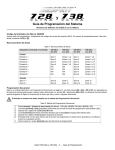
639/640 LCD keypads
616/626/633 LED keypads
Note: the 640
keypad can be
used with the
748ES panels but
will not display
correct event list
codes.
To disable the keypad zone (when keypad zone supervision is deactivated):
616/626: Connect the blue wire “ZONE” to the black wire “COM” and remove EOL jumper 2.
633/639/640: Connect a 1k" resistor between the zone terminal and the com terminal.
ZONE INPUT TERMINALS
The system hardware will recognize the following conditions for each zone:
Single Zone Connections
Note: Keypad zones always use a 1K" EOL resistor.
ZONE connection, without EOL resistor (N.C. contacts)
address 088, key [MEM] = "on"
key [10] = "off " (default)
key [11] = "off " (default)
8
IM748ES
ZONE connection, with EOL resistor
(N.C. and N.O. contacts) (UL/ULC Configuration)
address 088, key [MEM] = "off" (default)
key [10] = "off " (default)
key [11] = "off " (default)
ZONE connection, without EOL resistor, with tamper recognition
(N.C. contacts)
address 088, key [MEM] = "on"
key [10] =
See "Tamper/wire Fault Definitions
key [11] =
and Options"
ZONE connection, with EOL resistor, with tamper recognition and with wire
fault (short circuit) recognition (N.C. contacts) (UL/ULC Configuration)
address 088, key [MEM] = "off "
key [10] =
See "Tamper/wire Fault Definitions
key [11] =
and Options"
Tamper/wire fault transmits separate code.
TAMPER/WIRE FAULT DEFINITIONS AND OPTIONS
When using 2 zone resistors, the panel offers four possible definitions for tamper/wiring recognition,
independent of zone definition.
"Tamper/wire” disabled
(Address 088, Key [10] "off", Key [11] "off")
Tamper/wiring failure recognition is disabled. (Not allowed by UL listed systems, must be enabled.)
"Trouble" enabled
(Address 088, Key [10] "off", Key [11] "on")
Tamper/wiring failure will generate an alarm, when armed. A trouble report code will be sent to the central
when disarmed.
"Silent alarm" enabled
(Address 088, Key [10] "on", Key [11] "off")
Tamper/wiring failure will generate a silent alarm (no siren) when the system is disarmed. Alarm and
trouble report codes will be sent to the central, when the system is armed.
"Audible alarm" enabled
(Address 088, Key [10] "on", Key [11] "on")
Tamper/wiring failure will generate an audible alarm armed or disarmed (siren). Alarm and trouble
report codes will be sent to the central.
Exception: When the zone definition is "24 hour", the tamper definition follows the audible/silent alarm
arm definition of the "24 hour" zone.
Tamper recognition addresses:
Tamper report and restoration codes should be programmed at addresses 472-495 and 510.
9
IM748ES
FIRE CIRCUIT
The fire zone (enabled by defining zone 3 as "24 hour”) should always be connected with
a 1K" EOL resistor (PN201100200-PRT on UL systems). If there is a line short in the fire
zone, a fire alarm will be generated. If the line is "open", a "fire loop" trouble report will be
sent to the central and trouble indicator [11] will illuminate on the LED keypad.
For UL/ULC installations, a 4 wire, latching, smoke detector (UL - Falcon Model 5454,
ULC - BRK Model 2412) must be used. To supervise power supply, an “end of line”
relay (Model MR3) is installed. This relay’s contacts will cause a FIRE TROUBLE in the
event the power is interrupted.
To reset (unlatch) smoke detectors after an alarm, power to detectors must
momentarily be interrupted. To do so, connect the negative (-) side of smoke
detector power to PGM1. PGM1 should then be programmed “Timed N.C.”
(normally closed), programmed to “open” when any two keys on the keypad
are pressed simultaneously.
Example:
To program PGM1 to conduct smoke detector reset when [CLEAR] and [ENTER]
are pressed at the same time.
Address 039 = [BYP] [2ND]
Address 040 = [5] [10]
Address 042 = [2ND] [6]
Address 056 = [10] [10] [4]
TELEPHONE LINE CONNECTION
Connect the incoming telephone company wires into "TIP"
and "RING". Wires should then be run from "T1" and "R1" to
the installation's phone system.
POWERING UP THE UNIT
When keypads are installed far from the control panel, a keypad should be temporarily connected close
to the panel to conduct "power-up" testing. Connect the transformer. After 10 seconds, begin testing the
unit. Enter random commands on the keypad. It should "beep" in response to these commands. Open a
zone to ensure that keypad and panel are responding to signals. If the keypad does not respond and
indicator lights do not illuminate, check for AC voltage at the “AC” terminals. If 16VAC is flowing, then
keypad wiring should be verified. Also check for a short between "black" and "red” keypad wires.
Panel Programming Methods
To conduct panel programming, use the keypad or initiate communication with Espload (see below). Use
of Espload is highly recommended, as it greatly reduces the potential for data entry errors during programming. For Keypad Programming instructions, refer to "Programming Guide".
Battery Hook-Up (required on UL/ULC installations)
Use a 12VDC 7AH rechargeable acid/lead or gel cell battery. Connect "red"
battery lead to positive battery terminal, and "black" battery lead to negative
battery terminal. Reversed connections will blow the battery fuse. Battery
should not be connected until AC panel connections have been made. [TRBL]
key should illuminate. Pressing [TRBL] causes key [8] to illuminate (trouble
indicator for "timer loss"). (See "Trouble Display Monitoring" section, page
27-28.) Warning: Do not connect battery until all wiring is completed.
10
IM748ES
Battery Test
Panel conducts dynamic battery test under load every 60 seconds. If the battery is disconnected, or capacity
is low, trouble indicator key [1] illuminates. Key [1] also comes “on” if battery voltage drops to 10.5 volts while
panel is running on battery power (with no AC). At 8.5 volts, the panel shuts down and all outputs close.
ESPLOAD
The 748ES can be remotely programmed with Espload upload/download software, or on site using
Espload and a ADP-1 adapter. Advanced Espload software can carry out fast upload or download, and
provides many powerful features, including a comprehensive "monitoring" mode to oversee all panel activity, a "scheduler" to initiate preprogrammed tasks at set intervals, and a "batch" mode to carry out preprogrammed tasks following a call from the panel. There is no limit to the number of account files or panel
defaults that can be created, and thousands of programming combinations can be assigned to PGM outputs using Espload. Espload can be converted to the language of your choice, and individualized help
menus can also be generated. Contact your local Paradox Distributor for your copy of Espload software.
KEYPAD
To program Esprit panels via the keypad, first complete the programming work sheets and follow the programming procedures outlined in the "Programming Guide".
PROGRAMMABLE FEATURES
Hexa Programming:
All digits from 0 to F are valid. Programming values are programmed into memory locations from address
000 to 043 and from address 300 to 527.
1) Press [ENTER] + installer code.
2) [ENTER] will flash (programming mode).
3) Enter 3 digit memory address.
4) Enter 2 digit data.
5) Go to step 3 for next address.
To exit programming mode, press [CLEAR].
Streamlined Section Programming:
To begin programming:
Press [ENTER] + installer code + [7]. ([ENTER] and [2ND] keys will flash.)
Enter 2 digit section for programming (00 - 67). ([ENTER] key is "steady" and [2ND] key is "off".)
Enter 8 digits to program the section. Keypad will beep, to show section has been programmed.
Data is saved and the next section is made available for programming.
To select a specific section, press [CLEAR] or [ENTER]. ([ENTER] and [2ND] keys will flash.)
Enter 2 digit section (00 - 67). ([ENTER] key is "steady" and [2ND] key is "off".)
To exit programming mode, press [CLEAR].
Installer Code:
(Addresses 000, 001, 002)
SECTION 00
(Use only numeric keys from [1] to [10] to enter installer code. Key [10] = 0.)
The default installer code contains 6 digits. Default code is 747474. (Codes can also be programmed to
contain 4 digits, address 088, [9] "on".) Create a new installer code by entering the values of 1st and 2nd
digit at address 000, 3rd and 4th digit at address 001, and 5th and 6th digit at address 002.
The installer code has access to all programming addresses, except 128-299. It does not provide access
to arming/disarming or user code programming. It can be used to modify itself.
Related features:
"Installer lock" 058
"User/access code length" 088, [9]
11
IM748ES
Panel Answer Options:
(Address 003)
SECTION 00
The first digit entered disables the “Answering Machine Override” (key [2ND] or key [1]), or determines
the period of time between first and second call.
The second digit entered determines the number of rings required before the panel will answer.
If [2ND][2ND] is entered, the panel will not answer. (Default value is [2ND] [8].)
Panel Identifier:
(Addresses 004-005)
SECTION 01
This four digit code identifies the control panel to the PC before uploading can be initiated. Each pair of
code digits has its own memory address. There is no default code. Any hexa digits from 00 - FF can be
entered. Program first 2 digits in address 004 and second 2 digits in 005.
Related features: "Panel Answer Options" 003
"Call back" 086, [4]
PC Password:
(Addresses 006-007)
SECTION 01
This four digit download password identifies the PC to the panel, prior to beginning the programming
download process. Program the first 2 digits in address 006 and the second 2 digits in 007.
Telephone and Account Numbers
Three telephone numbers can be programmed: a PC telephone number and two central station numbers.
Each number can contain a maximum of 16 digits. Special instructions can be entered in the telephone
numbers using the following keys:
[10]
= the number "0"
[BYP] = switch from pulse to tone while dialing
[MEM] = pause 4 seconds
[11]
=*
[12]
=#
[TRBL] = end of number
If only one central station telephone number is available, the same telephone number must be programmed for telephone number 1 and 2. A separate "communicator reporting" format can be selected for
each central station telephone number at address 038.
Computer telephone number:
(Addresses 008-015)
SECTION 02 - 03
The PC download telephone number is dialed in three situations. It is dialed when communication with
PC is initiated from the keypad. It is the automatic "call back" number, when the "call back" feature is
enabled (086, [4] "on"). If the event buffer is ready to report, and "automatic event buffer transmission"
feature is enabled (088, [2ND] "on"), this number will be dialed in order to download the event list.
Related features: "Panel Identifier" 004-005
"PC password" 006-007
"Call back" 086, [4]
Central station telephone number 1
Central station telephone number 2
(Addresses 016-023)
SECTION 04 - 05
(Addresses 024-031)
SECTION 06 - 07
The panel can communicate with two central station numbers. Each of the numbers can be assigned a
separate reporting format.
Related features: "Communicator Formats" 038
"Reporting options" 086, [11] and [12]
Espload note: Upon alarm, upload/download in progress will be interrupted and the panel will call the central.
12
IM748ES
System account codes (system "A"/ "B")
(Addresses 032-035)
SECTION 08
All report codes are preceded by a system account code to ensure correct identification of active zone(s)
in a partitioned system. If partitioning is deactivated, the same value should be programmed for
both account numbers. To program account codes for System "A" and "B", press [ENTER] + installer
code + [7] + [10] [8]. The first four digits entered after this sequence correspond to the System "A"
account code, and the last four digits to the System "B" account code.
Time Correction
(Address 037, second digit)
If you notice a gain/loss in panel time, calculate the average
gain or loss per day, and select the “opposite” amount
from the following table to automatically correct the time
setting every 24 hours.
SECTION 09
Ex: Panel loses 4 minutes per month.
This represents an average loss of 8 seconds per day.
Select key [2] - plus 8 seconds - to correct the time
setting.
Enter any value for the first digit i.e. [2ND] at address 037.
Communicator Formats
(Address 038)
SECTION 09
Ademco contact ID (all codes reported)
(key [10])
All report codes are preprogrammed in this DTMF reporting format. There is no need to program values for
addresses 300-527 if both central station numbers use this format. Contact ID event codes are listed below:
Ademco contact ID (programmable codes reported) (key [9])
All addresses from 300 to 527 programmed with values other than [2ND] [2ND] will report the contact ID
codes corresponding to the values programmed (according to the “Programmable Contact ID Event
Codes” table in the Programming Guide).
Ademco express
(key [8])
This high speed reporting format communicates 2 digit events programmed in addresses 300 to 527 at a
speed of 2 seconds per event.
DTMF - no handshake
([TRBL] key)
All addresses from 300 to 527 programmed with values other than [2ND] [2ND] will report the contact ID
codes corresponding to the values programmed (according to the “Programmable Contact ID Event
Codes” table in the Programming Guide). This format can be utilized in reporting situations where a central station receiver is not connected to the telephone number. It's useful for personal reporting where a
"handshake" is not required. (In "double reporting" mode, first central station number can be connected
to a receiver, while second can be used for personal reporting using "no handshake" format. The panel
will make two attempts to call the "no handshake" number.)
13
IM748ES
Standard pulse formats
Ademco slow, Silent Knight, Sescoa, and Radionics are programmable with keys [2ND] to [7].
Programmable Output (PGM) Types
(Address 039)
SECTION 09
Regular N.O. Solid state switch conducts to negative (50mA*) upon an event or events, and returns to its
original state (N.O) once the conditions that triggered it have terminated.
Regular N.C. Solid state switch opens circuits from ground upon an event or events and returns to its
original state (N.C.) once the conditions that triggered it have terminated.
Timed N.O.
Solid state switch conducts to negative (50mA*) upon an event or events and remains activated for the amount of time programmed at address 056.
Timed N.C.
Solid state switch opens circuits from ground upon an event(s) and remains activated for
the amount of time programmed at address 056.
"OR" logic
Causes the programmable output command to occur when one or more selected events
from a specified group of events take place (example: key [1] OR [2] is pressed on keypad.)
"AND" logic
Causes the programmable output command to occur when all selected events from a specified group of events take place (example: key [1] AND key [2] are pressed.)
"EQUAL" logic Causes the programmable output command to occur when all events from a specified
group of events take place (example: key [1] and [2] are pressed but [3], [4], [5], [6], [2ND]
and [TRBL] are not pressed.)
*UL tested for 30mA only.
14
IM748ES
Typical PGM (Programmable Output) Programming
FUNCTION
DESCRIPTION
PGM 1
Add. 039
1ST digit
*Ground start Pulse
PGM 2
Add. 040
Add. 042
Add. 039
2ND digit
Add. 041
Add. 043
Provides 3 sec. pulse before
communication attempt.
[5]
[5]/[2]
[2ND]/[8]
[5]
[5]/[2]
[2ND]/[8]
(Timed N.O.)
Push key [1] and [2]
(Regular N.O.)
Provides output when keys [1] and
[2] are pressed simultaneously.
[1]
[5]/[8]
[2ND]/[6]
[1]
[5]/[8]
[2ND]/[6]
System armed
(Regular N.C.)
Output removed when system
armed.
[9]
[2]/[11]
[2ND]/[8]
[9]
[2]/[11]
[2ND]/[8]
Strobe output
(Regular N.O.)
Provides latching output on
alarm, until disarmed.
[2ND]
[2]/[12]
[2ND]/[2]
[2ND]
[2]/[12]
[2ND]/[2]
Fail to communicate
(Timed N.O.)
Provides output upon fail to
communicate for 2 minutes.
[5]
[2]/[6]
[2ND]/[4]
[5]
[2]/[6]
[2ND]/[4]
2nd telephone line relay Provides output after one failed
(Regular N.O.)
communication attempt.
[2ND]
[7]/[10]
[2ND]/[MEM]
[2ND]
[7]/[10]
[2ND]/[MEM]
Kiss off
(Timed N.O.)
[5]
[7]/[BYP] [2ND]/[8]
[5]
[7]/[BYP] [2ND]/[8]
Provides 3 sec. output after signal
received at monitoring station.
*Not permitted on UL listed systems.
Note: For other PGM operations, use Espload software by programming the desired PGM function and
pressing F8 to see the keypad programming codes and address. If other programming options are
needed, fax your requests to Paradox Technical Support at 514-491-2313.
Special Timing Functions
3 Digit Decimal Value Programming
Decimal programming is used to program addresses 044 to 061. Values entered must contain 3 digits.
Decimal value programming:
1) Press [ENTER] + installer code. ([ENTER] key will flash.)
2) Enter 3 digit address (044 to 061).
3) Enter 3 digit DECIMAL value.
4) To erase, press [CLEAR]. To save, press [ENTER].
5) Repeat from step 2 onward for next address. To exit programming mode press [CLEAR].
“No movement”
If a time is programmed at address 055, and a report code is entered at address 517 (SECTION 65), the panel
will send a report to the central, when there is no movement in the protected area for a designated time period.
"Late to close"
If the system is not armed by a specified time (addresses 044, 045) the code programmed at address
516 (SECTION 65) will be transmitted.
Auto arming
The panel can be programmed to automatically arm itself every day in two ways: at the specified time programmed at addresses 044, 045 and/or once the "no movement" delay has elapsed (address 055). To
program "auto arming", go to address 086 and enable key [5] (auto arm on time), and/or key [6] (auto
arm on "no movement"). All zones must be closed in order for the system to auto arm. If panel fails to
auto arm, only the “late to close" (address 516 (SECTION 65)) or the "no movement” (address 517 (SECTION 65)) report will be transmitted. The "auto arm" report is programmed at address 300 (SECTION 11).
15
IM748ES
Operational note regarding special timing functions
The time programmed at addresses 044 and 045 can be used to:
• Transmit “Late to Close” code, address 516 (SECTION 65), if the system is not armed by a specified time.
• Auto-arm the system and if programmed, transmit the arming code at address 300 (SECTION 11)
after transmitting the “Late to Close” code (as above).
The time programmed at addresses 047 and 048 can be used to:
• Specify the time of day for the Test Report (code programmed at address 512 (SECTION 64).
The amount of time programmed at address 055 (Max = 63.75 hours) can be used to:
• Transmit the “No Movement” code, address 517 (SECTION 65), if there is no movement in the protected
area while the system is disarmed.
• Auto-arm the system and if programmed, transmit the arming code at address 300 (SECTION 11)
after transmitting the No Movement code (as above).
The "Late to Close" code programmed at address 516 (SECTION 65) will be transmitted:
• At the time programmed at addresses 044 and 045 if the system is not armed.
The "No Movement" code programmed at address 517 (SECTION 65) will be transmitted:
• After the time programmed at address 055 expires.
The amount of time programmed at address 056 (Max = 127 minutes) can be used to:
• Designate the length of time a programmable output (PGM) will remain active following a specified event.
Auto test report options
Reports the code programmed at address 512 after the number of days programmed at address 046, at
the time programmed at addresses 047, 048. (To disable, program 000 at address 046.)
Auto arm options
1) Send a "late to close" code programmed at address 516.
2) Auto arm the system (on time) if enabled at address 086, key [5].
3) Auto arm the system (no movement) if enabled at address 086, key [6].
Exit Delay
(Address 049)
Range 001 to 255 seconds (factory default 060 seconds). Applies to all zones upon arming.
Entry Delay 1
(Address 050)
Range 001 to 255 seconds (factory default 045 seconds). Applies upon entry to all zones not selected at
addresses 100 to 114.
Entry Delay 2
(Address 051)
Range 001 to 255 seconds (factory default 045 seconds). Applies to all zones selected at addresses 112,
114, upon entry.
Bell Cut-off Time
(Address 052)
Range 001 to 255 minutes (factory default 005 minutes).
Zone Speed
(Address 053)
Range 001 to 255 X 15mSec., (factory default 600 mSec). Maximum time 3.8 seconds.
Power Failure Report Delay
(Address 054)
Range 001 to 255 minutes, (factory default 030 minutes), (000 = disabled). Delay code reported at address 499.
"No Movement" report time
(Address 055)
Range 001 to 255 X 15 minutes. (Factory default 8 hours (000 = disabled)). System will automatically
arm after programmed number of minutes of inactivity if enabled at address 086, key [6], or will transmit
code programmed at address 517. (Maximum time 63.75 hours)
16
IM748ES
PGM Timer Setting
(Address 056)
Range 001-127 sec. or 1 minute (enter 129) 127 minutes (enter 255). (Add required number of minutes to 128)
i.e. For 5 minutes = 128 + 5 = 133
For 127 minutes = 128 + 127 = 255
Applies to PGM 1 and 2 if selected at address 039. (Maximum time, 127 minutes)
Intelli zone
Delay
(Address 057)
This time limit, set between 10 and 255 seconds, is the period in which two intellizone detections must
take place, or in which an intellizone must remain open, in order for an alarm to be communicated.
Note: do not use the Intellizone feature and an entry delay on the same zone, otherwise an alarm may
occur as a user tries to disarm the system.
Installer Lock
(Address 058)
If 147 is programmed at address 058, all programming will be locked and will not be affected when the
system is reset.
Programmable Delay Before Alarm Transmission
(Address 059)
This time limit, set between 5 and 63 seconds, is the period of time before reporting begins the first time
an alarm is generated. During the waiting period, system disarm will cancel all pending reports.
Note: For UL listed systems the time limit must be set to a maximum of 30 seconds.
Recent Closing Delay
(Address 060)
This time limit, set between 1 and 255 seconds, begins as soon as the system is armed, and continues
until expiration of the period programmed. Every time an alarm occurs during this period, a “recent close”
code (address 519) will be sent to the central.
System Options
(Default = "off" for addresses 062-126)
Feature select programming
"ON”/"OFF" status of the key lights determines feature selection.
In programming mode, enter 3 digit memory address (062 to 126).
To save entries, press [ENTER]. To exit programming mode press [CLEAR].
Code priority
(Addresses 062 to 078)
If partitioning is disabled
(Address 086, key [8] "off ")
Addresses 062-066: Lighted keys indicate which user codes can activate "stay" arming.
Addresses 068-072: Lighted keys indicate which user codes can activate force "away” arming.
Addresses 074-078: Lighted keys indicate which user codes can "bypass" zones.
If partitioning is enabled
(Address 086, key [8] "on")
Addresses 062-066: Lighted keys indicate which user codes are assigned to System "A".
Addresses 068-072: Lighted keys indicate which user codes are assigned to System "B".
Addresses 074-078: Lighted keys indicate which user codes can "bypass" zones.
(See also page 25.)
TLM options
(Address 086, key [2ND] and key [1])
The system verifies the existence of a telephone line every 4 seconds. After successful tests, the dialer
LED (green light) flashes briefly on control panel. If the test fails, LED illuminates 4 seconds "on", then 4 seconds "off ". TLM trouble will be activated when less than 3 volts are detected in 4 consecutive tests.
Note: When the dialer detects a telephone ring, the TLM test stops for 1 minute.
There are three options for TLM use.
(1) Line test failure can generate a trouble indication.
(2) Line test failure can generate a trouble indication and an
alarm if the system is armed.
(3) Line test failure will cause a silent zone or a silent panic
alarm to switch to audible mode.
17
IM748ES
Arming using PS1 or keyswitch
(Address 086, key [2] and key [3])
The PS1 bedside remote arming module or keyswitch can be used to stay arm, full arm, or disarm the
system. The PS1 keyswitch is enabled at address 086, key [3].
Key [2] "off": PS1 or keyswitch "regular" arms system.
Key [2] "on": PS1 or keyswitch "stay" arms system.*
*Note: If partitioning is enabled (address 086, key [8] "on"), PS1 arms system "A" only. Use of PS1 is not
recommended for partitioned systems.
Call back
(Address 086, key [4])
For extra security, the panel can be programmed to call the PC back when communication is attempted
by the PC. The panel will first answer the call, then Espload and the panel will verify identification codes.
The panel will then hang up and call the PC back and establish communication. Espload automatically
goes into the “wait for call mode”, ready to answer when the panel calls back. The identification codes
are verified again before allowing access to the panel.
Related features:
“Computer telephone number” 008-015.
Auto arm
On Time:
(Address 086, key [5])
The panel may be programmed to arm at the same time every day. Program both the hour and minute
(addresses 044, 045) for arming. A late closing code may be programmed (address 516).
Related features: “Auto arm” 090, [2]
“Auto/Espload Arm” 300
"Auto arming" p.15.
No Movement:
(Address 086, key [6])
If zone activity is not detected for a programmed period (address 055) while disarmed, the panel can auto
arm and/or send a "no movement" report (address 517). Refer also to "No movement" p. 15.
Touch tone options
(Address 086, key [7])
Tone (key [7] = "on") or pulse dialing can be programmed. If "pulse" is chosen for a central station phone
number, "tone" dialing can be programmed for the other number. [BYP] ("switch from pulse to tone")
should be entered in the second phone number during programming.
Partitioning
(Address 086, key [8])
Partitioning is activated, (key [8] "on"). The panel's fully programmable zones (plus 2 remote keypad
zones) can be divided into two systems. (See “System Partitioning”, page 25.)
Silent alarm
(Address 086, key [9])
Key [9] "off":
Silent zones/panics generate a silent alarm. Zones defined as "silent" at addresses 096-098 and keypad
panic zones will not cause an audible alarm, however, the keypad "armed" light will flash and the alarm
condition will remain until a valid user code is entered.
Key [9] "on":
Silent zones/panics generate only a report (The red keypad LED does not flash, and there is no need to
"reset" the silent alarm.)
Silent delay zones generate an entry delay beep, and a report at the end of the entry delay.
Zone restore is always reported upon zone closure.
Memory display, auto zone shutdown are always active for silent zones when enabled at address 086, key [TRBL].
Silent alarms can be monitored by a PGM output. (Silent flag is cleared on report or disarm.)
On split reporting, silent zones/panic are reported to Telephone #1.
Dialing pulse rates
(Address 086, key [10])
This selection reflects the ratio between “pulse” time and "quiet" time. Select Pulse Europe for a 1:2 ratio
(Key [10] = "off"), Pulse USA for 1:1.5. (Key [10] = "on")
Reporting options
Regular reporting
(Address 086, key [11] “off” and key [12] “on”)
To activate central station reporting, the feature must be enabled and all required reporting codes, except
when using “Ademco contact ID (all codes reported)”, must be assigned a value other than [2ND][2ND].
18
IM748ES
To establish communication, the communicator takes the telephone line and waits for a dial tone. If a dial
tone is identified, the communicator will dial the first central station telephone number. If a connection is
made, system report will take place and the communicator will hang up upon completion. If for any reason, communication is interrupted, the communicator will dial the 2nd central telephone number and
report only the events that were not reported during the interrupted attempt.
During a communication attempt, the communicator waits for a dial tone for up to 8 seconds. Even if a
dial tone is not found, the communicator will dial the central station.*** After 60 seconds, if communication has not been established, the dialer will hang up, wait 5 seconds and try the second number. This
sequence will be repeated 8 times, switching back and forth between the 1st and 2nd number. (Regular
reporting dialing procedure: 1,2,1,2,1,2,1,2, "communicator report failure".)
***This feature is useful for PBX systems, which do not provide a dial tone. You can program the dialing
sequence required to get a line on a PBX system, and this sequence will be added before the central
station number. If there is a time delay between dialing and getting a line, this can be programmed
into the dialing sequence using the [MEM] ("pause") key.
After 8 unsuccessful attempts, the redial sequence ends and "communicator report failure" will appear in the
keypad’s trouble display (key [7] "on"). When the next reportable event occurs, (even if it is not programmed
to report to the central), the communicator will try again to establish communication. If successful, all events
stored in the event buffer that have not yet been reported will be communicated to the central.
Split reporting
(Address 086, key [11] "on", key [12] "off")
All "system" reports (i.e. trouble reports, arm/disarm reports, etc.) are sent to Telephone #2, until an alarm is
generated. Following alarm generation, all activity, including alarm and restoration reports, is sent to Telephone
#1 until the system is disarmed. When there is an alarm, any ongoing communication (upload/download or
reporting to Telephone #2) will immediately be stopped and the panel will dial Telephone #1.
Alarm reports dialing procedure:
"System" reports dialing procedure:
(1,1,1,1,1,1,1,1, "communicator report failure")
(2,2,2,2,2,2,2,2, "communicator report failure")
Double reporting
(Address 086, key [11] "on", key [12] "on")
The panel will transmit all reports to both programmed telephone numbers. If, after 8 attempts using either
number, communication is not established, "communicator report failure" will be displayed by key [7].
Double reporting dialing procedure:
(1,1,1,1,1,1,1,1, "communicator report failure")
(2,2,2,2,2,2,2,2, "communicator report failure")
Note: To stop communication attempts until the next reportable event, press [ENTER] + installer code + [STAY].
Bell squawk
(Address 086, key [MEM])
Bell/siren will emit a 0.5 second “squawk” once upon arming, and twice upon disarming.
(Key [MEM] "on" = enabled)
Auto zone shutdown
(Address 086, key [TRBL] "on")
Key [TRBL] "on" = Zones that initiate 5 consecutive alarms during the same armed period will be automatically bypassed. (Zones must be bypass-enabled at addresses 124-126.) After a zone
has been bypassed, the panel can send a "zone shutdown” report to the central (if programmed to do so at addresses 448-471).
Note: Once auto zone shutdown has been enabled, it will either be activated after 4 "zone closure"
restoration reports or 4 "bell cut-off " restoration reports, depending on which type of alarm restoration code has been activated at address 088, key [BYP].
Automatic event buffer transmission
(Address 088, key [2ND])
Key [2ND] "on" = system will dial the computer telephone number programmed in Section 02 and 03
(addresses 008-015) to upload the contents of the event buffer to the PC. (Espload must be in "wait for
call" mode.) The system will make two attempts to call the PC when the event buffer reaches 50%
capacity. If communication is established, the system will then proceed to report the contents of the event
buffer to the PC. Should transmission be interrupted before the complete contents of the buffer can be
19
IM748ES
transmitted, or if after two attempts, communication is not established, the system will wait until the event
buffer is full, before attempt to communicate with the central again.
If communication is established, the system will then proceed to report the contents of the event buffer to
the PC. If after two attempts, communication is not established, each subsequent new event will erase
the oldest event in the buffer, until the event buffer once again reaches 50% capacity.
Enable keypad panic signals
(Address 088)
Key [1] "on" = Panic 1 (keys [1] and [3], PS1) enabled
Key [2] "on" = Panic 2 (keys [4] and [6]) enabled
Key [3] "on" = Panic 3 (keys [7] and [9]) enabled
Keypad panic options
Key [4] "off " = Panic 1 silent
Key [4] "on" = Panic 1 audible
(Address 088)
Key [5] "off " = Panic 2 silent
Key [6] "off " = Panic 3 silent
Key [5] "on" = Panic 2 audible
Key [6] "on" = Panic 3 fire
Silent operation
When panic keys [1] and [3], OR [4] and [6], OR [7] and [9] are pushed simultaneously for 2 seconds or
PS1 is used, a single confirmation beep is sounded, codes programmed at addresses 513, 514, and 515
are transmitted and the alarm latches, flashing the keypad "armed" light until reset by a user code.
Audible operation
When panic keys are pushed in addition to alarm codes being transmitted, the alarm output (bell/siren)
will activate until reset by a user code or until the bell cut-off time (address 052) expires.
Fire operation
Same as audible operation except that bell/siren output will be pulsed (intermittent "on"/"off ").
"One key" arming enable
(Address 088)
Key [7] "on" = Pushing key [10] for 2 seconds "full" arms system.
Key [8] "on" = Pushing key [11] for 2 seconds "stay" or “system A” arms system.
User/access code length
(Address 088)
Key [9] "off " = 6 digit user/access codes and installer code.
Key [9] "on" = 4 digit user/access codes and installer code.
Tamper/wire fault definitions
Note:
(Address 088)
If key [10] and key [11] are both "off ", this means that tamper and wire faults will not be recognized. See "Zone Input Terminals" page 8-9, "Tamper/Wire Fault Definition and Options", page
9, and "Tamper/wire Fault Definition table" in the "Programming Guide".
Beep on exit delay
(Address 088)
Key [12] "on" = The keypad will sound on exit delay (except when in “stay” arming). Frequency of intermittent beeps increases during the last 10 seconds of the exit delay period.
Zone restore transmission
(Address 088)
Key [BYP] "off " = If zone is closed, restoration code will be transmitted after "bell cut-off".
Key [BYP] "on" = Restoration code transmitted as soon as zone is closed.
Silent zones are always restored as soon as they are closed.
Zones with EOL resistors
(Address 088, key [MEM])
See "Zone Input Terminals" pages 8-9.
Always report disarm
(Address 088)
Key [TRBL] "off " = always reports disarm codes.
Key [TRBL] "on" = reports disarm code only after alarm.
Exclude power failure from trouble display (Address 090, key [2ND])
Key ="on": Power failure will not make the [TRBL] key flash.
This trouble condition may still be viewed after pressing [TRBL].
20
IM748ES
Arming Options
Auto arm
(Address 090, Key [2])
Key ="off ": When system auto arms (on time or "no movement"), "regular" arming will take place (if all
zones are closed).
Key ="on": When system auto arms (on time or “no movement”), "STAY" arming will take place (if all
zones are closed). If zone partitioning is programmed (address 086, key [8]), System “A” will
arm. (See also "Auto arming" page 15.)
No tamper bypass
(Address 090, key [6])
Key ="off ": Device tamper will not follow zone bypass.
Key ="on": Device tamper will follow zone bypass.
Audible trouble warning
(Address 090, Key [9])
Key ="on": Trouble conditions cause intermittent audible trouble warning on keypad. To silence, push [TRBL].
Note: Must be enabled for UL listed systems.
Duress alert
(Address 090, Key [10])
Key ="on": A duress code can be sent to the central whenever a person enters it on a keypad.
This sends a silent alert if a user is forced to disarm the system. Only user 48 can use this feature.
Keypad zone supervision
Keypad 1 zone supervision
(Kpd 1)
Keypad 2 zone supervision
(Kpd 2)
(Address 090, key [11])
(Address 090, key [12])
“ON” = enabled
“OFF” = disabled
“ON” = enabled
“OFF” = disabled
Keypad zone supervision allows the system to verify the presence of a keypad and its keypad zone(s).
When enabled, only two keypad zones (one configured as keypad 1, and one configured as keypad 2)
can be used at one time. Any other keypad zone terminals must be shorted.
If using a 616, 626, or 633 LED keypad with software version 3.9 or earlier, OR a PS1 version 1.1, OR a
639/640 keypad with its keypad zone supervision feature disabled (address 32, key [3] “off”), or if the keypad zone is not used:
• KEYPAD ZONE SUPERVISION FEATURE MUST BE “OFF”.
If using a 616, 626, or 633 LED keypad with software version 4.0 onward, OR a PS1 version 2.0 onward,
OR a 639/640 LCD keypad with its keypad zone supervision enabled (address 32, key [3] “on”):
• KEYPAD ZONE SUPERVISION FEATURE MUST BE “ON”.
Related features: Keypad connections. p.8
Zone Definition
(Addresses 092-126)
Zone definition is assigned during "feature selection" programming. Turning zone key "on" or "off" at
addresses 092-126 assigns a particular definition to the zone. (See “Programming Guide”).
Intelli zone
definition
(Addresses 092, 094)
Key "on": When an alarm condition occurs on a zone defined as intellizone, a timer (set between 10-255
seconds, at address 057) is triggered. An alarm will only be generated if:
1) An alarm condition occurs on a second zone, within the specified time period.
2) The alarm condition, on the first zone, restores and reoccurs, within the specified time period.
3) The alarm condition, on the first zone, stays on for the complete duration of the specified time period.
Key "off": An alarm is generated as soon as the zone is opened. This feature should be disabled on UL
listed systems.
Note: do not use the Intellizone feature and an entry delay on the same zone, otherwise an alarm may
occur as a user tries to disarm the system.
Silent/audible
(Addresses 096, 098)
Silent zones (keys "on") report alarms without triggering bells/sirens. (Reminder: fire zone is never silent.)
Audible zones (keys "off ") will trigger a bell or siren upon alarm generation.
21
IM748ES
24 hour - fire/regular
(Addresses 100, 102)
"24 hour" zones (keys "on") generate alarms whenever the zone is detected, even if the system is not
armed. Zone 3 becomes a fire zone when defined "24 hour". The fire zone should always be connected
with a 1K" EOL resistor. If there is a line short in the fire zone, a fire alarm will be generated. If the line is
"open", a fire trouble report (if assigned at address 500) will be sent to the central, and trouble indicator
[11] and fire zone key [3] will flash on the keypad. Alarms in a fire zone generate an intermittent output
signal, regardless of system arming status.
Instant
(Addresses 104, 106)
"Instant" zones (key "on") will immediately generate an alarm when detected while the system is armed.
There is no entry delay.
Follow
(Addresses 108, 110)
"Follow" zones (key "on") are "instant" zones that switch to "delay" definition during entry delay.
Delay 2
(Addresses 112, 114)
One of two different zone delays (delay 1 & delay 2) can be assigned to each zone. Zones activated at this
address are assigned "Delay 2" definition. The length of zone entry delays is programmed at addresses
050-051. Any zones that are not activated at addresses 100-114 are assigned "Delay 1" zone definition.
Note: When more than one zone definition is selected, zone definition priority is assigned in this
order: (1) 24 hr., (2) instant, (3) follow, (4) delay 2 and (5) delay 1.
System assignment
(Addresses 116, 122)
Refer to "System Partitioning", page 25)
Related programming:
"Partitioning 086, [8]."
Bypass-enabled
(Addresses 124, 126)
"Bypass-enabled" zones (keys "on") are zones that can be bypassed during "manual bypass" arming and
auto zone shutdown. The fire zone cannot be bypassed.
Note: If a zone should not be bypassed, turn "off" its corresponding zone key.
Reporting Codes:
(Addresses 300-527) SECTION 11- 67
The panel can report information regarding system and "protected area" status to the central monitoring
station, when reporting is activated at address 086. All data to be communicated should be assigned a 2digit hexa reporting code, consisting of numbers from 0-F. Examples of two digit hexa code combinations
are [6] [BYP] and [9] [TRBL]. Written in hexa notation, these codes are [6] [D] and [9] [F].
Using the keypad for hexa digit entry, keys [10], [11], [12], [BYP], [MEM] and [TRBL] correspond to hexa
digits A, B, C, D, E and F, respectively.
The [2ND] key's value is "skip" (empty). It is ignored by the panel, so to avoid reporting a specific condition
to the central, enter [2ND][2ND] after the report address for that condition. Also, when programming 3 digit
account codes and 1 digit alarm codes (3-1 reporting), use [2ND] in lieu of the first digit.
All report codes are assigned to a system account, whether or not partitioning is activated. Arm/disarm
reports are assigned to System "A" when partitioning is "off", or to the system account to which they
belong, based on code priority assignment, when partitioning is activated.
Trouble and special report codes are always assigned to System "A".
Arming codes/disarming codes:
(Addresses 300-399) SECTION 11 - 35
System access codes can be programmed to generate hexa report codes that communicate the identity of the
user arming/disarming the control panel to the central monitoring station. Each user code can be assigned an
arm/disarm report code. Auto/Espload Arm will be reported to the central when Espload is used to arm the
control panel or when the system arms itself automatically (on “no movement” or at a specified time). Espload
disarm will be reported to the central when Espload is used to disarm the control panel. Arm/disarm with master code will be reported to the central when the master code or keyswitch is used to arm/disarm control panel.
22
IM748ES
Zone alarm codes:
(Addresses 400-423) SECTION 36 - 41
Alarm report codes programmed will be sent to the monitoring station, identifying the zones that are generating alarms.
Zone restore codes:
(Addresses 424-447) SECTION 42 - 47
Zone restoration codes programmed will be sent to the monitoring station, identifying zones returning to
normal status after alarms.
Shutdown codes:
(Addresses 448-471) SECTION 48-53
These codes are sent to the monitoring station to identify zones bypassed during “auto zone shutdown”
(address 086, [TRBL].)
Tamper trouble codes:
(Addresses 472-495)
These codes identify zone locations of tamper “troubles” to the central.
SECTION 54-59
Trouble codes:
(Addresses 496-503) SECTION 60 - 61
6 trouble status codes can be reported to the central, if programmed: max. auxiliary current, bell disconnect/max. bell current, battery disconnected/low voltage, power failure, fire loop trouble, and timer loss. (See
"Trouble Display/Monitoring", page 27-28, for a list of trouble conditions displayed on the keypad.)
Trouble restore codes:
(Addresses 504-511) SECTION 62 - 63
If trouble conditions occur and are reported, once normal status is re-established, a "restoration" code
can be transmitted to the central to indicate that the "trouble" situation has been rectified.
Note: All Tamper/Wire Faults must be restored before a “Tamper/Wire Fault” restoration code is transmitted.
Special codes:
(Addresses 512-527)
These codes are assigned to report 11 special status conditions.
SECTION 64 - 67
Test report
Test report will be reported to the central automatically at the day and time set for the
“auto test report” (addresses 046, 047, 048) or manually. To send a manual test report,
press [ENTER], followed by installer, master or user code 1, and [BYP] are pressed.
Panic 1
Panic alarm will be reported to the central if PS1 is used or if keys [1] and [3] are pressed
for 2 seconds.
Panic 2
Panic alarm will be reported to the central if keys [4] and [6] are pressed for 2 seconds.
Panic 3
Panic alarm will be reported to the central if keys [7] and [9] are pressed for 2 seconds.
Late to close
Will be reported to the central when the system has been armed (or not) by the required
time.
No movement
Will be reported to the central when there is no movement in the protected area for a
designated time period.
Partial arming
Will be reported to the central if the control panel is armed while any zones are
bypassed or when the system is force armed and stay armed.
Recent close
This code is sent to the monitoring station to notify that an alarm occurred shortly after
the system was armed (during the “recent closing” delay). This feature is designed to
help prevent unneeded response from the central.
Duress
A duress code is sent to the central whenever a person enters it on a keypad. This feature is primarily intended to send a silent alert if a user is forced to disarm the system
under threat. Only user 48 can use this feature.
Log-in (Espload) Will be reported to the central once the communication between the panel and the PC
is over.
Program change Will be reported to the central once programming mode is entered using the installer code.
23
IM748ES
The Esprit 's innovative keypads take a new approach to security features and functions. Each numeral
from 1 to 12 on the keypad represents an actual zone. When the [2ND] key flashes, the same numerals
represent a second set of 12 zones, zones 13 to 24. When the zone light is "off", the status in the protected zone is normal. If the zone light is "on", this means the zone is open.
"CONF" confirmation beep: an intermittent series of beeps indicating a successful keypad entry.
"END/REJ" end/rejection beep: 1 long tone indicates that the operation was incorrectly entered on the keypad.
SYSTEM ARMING/DISARMING OPTIONS
Regular System Arming (default code 474747)
(Without partitioning - for information on partitioned system arming, see page 25-26)
The green "ready" light must be illuminated. This "ready" indicator will only illuminate if all zones are
closed. All door/window contacts must be closed, and any movement in motion detector-protected areas
must be halted. When the "ready" light illuminates, a valid access code should be entered.
Upon entry of this code, the red "armed" light will illuminate, followed by the keypad "CONF" beep. (If the
access code is entered incorrectly, the "END/REJ" beep will sound. If an incorrect entry is made at any time,
press [CLEAR] and re-enter the data.) The green "ready" light will flash for the period of the exit delay, and
the [STAY] and [AWAY] keys will flash.
Note: Keypad will beep on exit if programmed at address 088, key [12].
Force (Away) Arming
[AWAY] + access code
To arm the system rapidly without waiting for the "ready" light, use the "away" force arming feature. The
[AWAY] key should be pressed, followed by a valid access code (addresses 068, 070, 072). Once the exit
delay expires, any open zones will not be considered “activated” by the panel. Open zones will not be protected, and will not generate an alarm or prevent arming. These “away” zones will become active (and
therefore, protected) as soon as they are closed. Armed status is indicated by illumination of the [AWAY]
key. A "partial arm" code will be sent if programmed.
Please note: This feature is not recommended for regular use because force arming with open zones can
reduce the efficiency of system protection.
Stay Arming
[STAY] + access code
When "stay arming" is activated, the security installation is "partially" armed. This means that only selected
STAY zones are armed (addresses 116, 118), so that users can remain in the protected area. This convenient feature (programmed at addresses 062, 064, 066) offers individuals arming the system the choice to
leave the premises during an exit delay (without altering the "stay arm" status), or remain on the premises.
A system user returning to a protected area that is "stay" armed can re-enter and disarm, as long as a valid
access code is keyed in during the entry delay. The [STAY] key flashes during “stay” arming.
Double "Stay" Arming
During the “stay” arming exit delay, pressing [STAY] (key [11]) again will switch all “stay” zones to instant
zones (no entry delays). Full system arming cancels "double stay" arming.
Fast "Regular" Arming
Key [10]
Fast arming is enabled at address 088 (key [7] "on"). If activated, when the ready light is on, pressing key
[10] for 2 seconds automatically arms the system. There's no need to enter an access code. This feature
can be used to permit selected individuals (i.e. maintenance workers, repair personnel) to full arm the system when leaving the protected area. (When partitioning is enabled, key [10] arms system "A" and "B".)
24
IM748ES
Fast "Stay" Arming
key [11]
Fast "stay" arming is enabled at address 088 (key [8] "on"). When activated, no "ready" light is required,
however "stay" zones must be closed to arm the system. Pressing [STAY] (key [11]) for 2 seconds automatically "stay" arms the system. (See "stay" arming features.)
Fast Exit
Exit while the system is armed in "stay" mode:
A: Fast exit and Stay
key [11]
To exit the premises and remain "stay armed": press key [11/STAY] for two seconds. The system switches
to "exit delay" mode ("ready" LED flashes). At the end of the "exit delay" period, the system will return to
"stay" arming mode.
B: Fast exit and Regular Arm key [10]
To exit the premises and "regular" arm: press key [10] for two seconds. The system switches to "regular"
arming (key [11] and [12] flash) with "exit delay" ("ready" LED flashes). At the end of the "exit delay"
period, the system is "regular" armed.
System Disarming
The protected area should be entered through a designated entry/exit door. The keypad sounder will beep to
remind user to disarm the system. A valid access code should be entered on the keypad, before the allotted
entry time expires. If the access code is entered incorrectly, press [CLEAR] and re-enter it. The "armed" light
will extinguish and the sounder will change to the "CONF" beep (series of short beeps) before silencing.
Alarm Memory
The memory light [MEM] on your keypad will illuminate if any alarm situations took place while your system
was armed. A record of all alarm situations that occurred is stored in memory. After disarming the system,
pressing once on the [MEM] key causes it to flash and brings up, in the keypad display, the alarm events
that occurred during the last alarm period. (Alarm events consist of all zones that generated alarms.)
SYSTEM PARTITIONING
By activating the panel's "partitioning" feature, zones can be divided into two distinct systems, with a
shared fire zone (zone #3). Both systems are controlled by one panel, making partitioning a particularly
useful feature in installations where shared security systems are more practical (i.e. office/warehouse,
apartment/condo complexes).
Partitioning
Partition "on"
(Address 086, key [8] "on")
Addresses 116, 118, 120, 122:
Zones can be assigned to system “A” (addresses 116, 118 zone key “ON”) and/or to system “B” (addresses
120, 122 zone key “ON”). A “common zone” is a zone that is not assigned to any system (it will be reported as
a “System A” zone). It is armed only when both systems are armed, and disarmed if system “A” or system “B”
is disarmed. A “dual zone” is a zone that is assigned to both systems (it will be reported as one of the system
(either “A” or” B”)). It is armed if either system “A” or system “B” is armed, and disarmed only when both systems are disarmed.
Note: When partitioning is not activated (address 086, key [8] "off") any zones selected at addresses
116, 118 will be armed upon "stay" arming.
Keypad display:
Both systems are displayed on the keypad at the same time. In partitioning mode, when System "A" is
armed, the [STAY] key flashes. If System "B" is armed, the [AWAY] key flashes. If both systems are armed,
both of these keys will flash.
25
IM748ES
Arming/Disarming
Code definition:
Addresses 062, 064, 066:
Addresses 068, 070, 072:
Addresses 074, 076, 078:
Partition "on" (Address 086, key [8] "on")
Designates access codes that arm System "A" zones.
Designates access codes that arm System "B" zones.
Designates access codes that can "bypass" zones
When a code is activated at both addresses (062-066 and 068-072), it can do the following:
• The code can fully arm the system. If the code is entered when systems "A" and "B" are disarmed, it
will completely arm the system.
• The code can fully disarm the system. If the code is entered when system "A" and "B" zones are
armed, it will completely disarm the system.
• When the system is partially armed (i.e. only System "A" or "B" is armed) entering this code will arm
the other system.
• The code can be used to selectively arm/disarm System "A" or System "B" zones.
Enter [11] + code to arm/disarm System "A" zones.
Enter [12] + code to arm/disarm System "B" zones.
Note:
Codes that are not selected at either address are disabled.
The master code can always access both systems and bypass zones.
• System "A" codes can stop sirens coming from System "B" zones (and vice versa), but will not disarm the other system.
• It is not possible to arm one system during the other system's exit delay.
Note:
When partitioning is not activated, (address 086, key [8] "off"):
Addresses 062, 064, 066 determines which access codes can activate "stay" arming.
Addresses 068, 070, 072 determines which access codes can activate "away" arming.
Addresses 074, 076, 078 determines which access codes can "bypass" zones.
26
IM748ES
Keyswitch/push-button arming/disarming (PS1)
In parallel to keypads, a keyswitch or push button can be used to arm/disarm the system. (The Esprit
PS1 can be installed in bedrooms or any other desired location.) Keyswitch/push button operation is
enabled/disabled at address 086, key [3]. Keyswitch can activate "regular" or "stay" arming, based on the
definition assigned at address 086, key [2]. (key [2] "off" = "regular" arming, key [2] "on" = "stay" arming)
If "stay" arming is activated, the keyswitch/push button (PS1) cannot be used to disarm the system if it is
in entry delay or if an alarm has been generated. In this case, the system can only be disarmed from a
keypad. (When partitioning is activated, the keyswitch can be used to arm/disarm System "A" regardless
of System "B" status. Pressing key [11] will arm System "A".) Pressing two keys on the PS1 simultaneously for 2 seconds will generate a "panic 1" alarm. (See "Keypad (Panic) Alarms” below).
ZONE BYPASSING
Bypassed zones will not generate an alarm. Manual bypass arming is employed when a system user
chooses not to arm the entire protected area. Only zones that have been defined as "bypass enabled"
(addresses 124, 126) can be selected by the user (addresses 074, 076, 078) during manual bypass arming. To bypass zones, enter [BYP] + a valid access code. [BYP] key will illuminate. When a zone light is
on, it indicates that the zone has been bypassed. Pressing [CLEAR] erases all bypass entries and currently bypassed zones and exits the bypass mode. Zones to be bypassed should then be re-entered. If
bypass information is correct, press [ENTER] to end and save bypass functions being programmed. [BYP]
key will remain illuminated, indicating that some zones have been bypassed. To cancel the zone bypass
"status" just entered, press [BYP] + a valid access code + [CLEAR]. Zone bypasses are automatically cancelled every time the system is disarmed, except in "24 hour" zones. If a "24 hour" zone is bypassed and
the system is subsequently disarmed, the "24 hour" zone will remain bypassed.
Note: If partitioning is used, zones assigned to the other system cannot be bypassed if the system is armed.
Bypass Recall
This feature permits system users to reinstate the latest zone bypass instructions saved in memory. By
pressing [BYP] while in bypass programming mode, previous bypass status is re-established. Even if a user is
in the process of entering new bypass information on keypad, one touch of the [BYP] key overrides new information and reinstates the preceding zone bypass instructions saved. (The fire zone cannot be bypassed.)
CHIME ZONES(applies only to 616, 626, 629 and 633 keypads)
Chime zones report a presence (movement or door opening) in selected zones by emitting a distinctive, rapid
intermittent beep. Each keypad is independently "chime" programmed and must be reprogrammed in the
event of total power loss. To enable a zone's chime feature on a LED keypad, press the desired zone key
from [1] to [6] until a rapid intermittent beep is heard. To enable the chime feature of the keypad zone connected to the particular LED keypad, use key [8]. To disable a zone's chime feature on a LED keypad, press
on the appropriate key until a steady beep is heard. To disable the LED keypad sounder (mute), press key [9].
KEYPAD (PANIC) ALARMS
These panels provide three keypad “panic” zones. Keys must be pressed simultaneously for 2 seconds
in order to activate. (Pressing 2 keys on the PS1 for 2 seconds generates a "panic 1" alarm.)
Alarm
Panic 1
Panic 2
Panic 3
Press keys
[1] & [3]
[4] & [6]
[7] & [9]
Alarm Code
Add. 513 (SECTION 64)
Add. 514 (SECTION 64)
Add. 515 (SECTION 64)
Silent/Audible
Add. 088, Key [4]
Add. 088, Key [5]
Silent/Fire
Add. 088, Key [6]
TROUBLE DISPLAY/MONITORING
Trouble status is continuously monitored by the panels which can recognize and display 10 different trouble conditions on the keypad or in Espload, and report 8 to the central station. (To send "trouble status
reports" to the central, 2-digit trouble report codes should be programmed.) When trouble conditions
occur, [TRBL] illuminates and if "trouble warning" is enabled (address 090, key [9] “on”) the keypad will beep
intermittently. Press [TRBL] to switch keypad to "trouble display" mode. [TRBL] flashes. Keys that are "on" indicate current trouble conditions. Press any key to return keypad to normal display.
27
IM748ES
Key [1]
No battery/low battery
Panel battery is disconnected, or capacity is low. Panel conducts dynamic battery test under load every
60 seconds. Key [1] "on" indicates battery is disconnected, or battery should be replaced because it
won't provide adequate back-up current in event of AC loss. Trouble indicator [1] also comes "on" if battery voltage drops to 10.5 volts while panel is running on battery power (with no AC).
Key [2]
Power failure
Activates when inadequate AC power goes to panel OR the power supply is unable to charge battery OR
the power supply voltage exceeds 14.9V. A report can also be sent to the central, and “power failure”
report delay time is programmable at address 054. Delay duration can be from 001 - 255 minutes (factory
default = 30 min). When a “power supply failure” trouble occurs, the [TRBL] key flashes rapidly. To
remove “power failure” from trouble display, key [2ND] should be “on” at address 090.
Key [4]
Bell disconnect
Bell is not connected to bell output. Note: When connecting bell to optional relay output, trouble indicator [4]
is "on" constantly. To avoid this, connect a 1K"#EOL resistor on bell output. If an internal siren is connected
to bell output, and an external siren to relay, the panel will only recognize the existence of the internal siren.
Key [5]
Maximum bell current
The bell output is microprocessor-controlled and will automatically shut down if current exceeds 3 amps upon an
alarm. After opening the short or reducing the load, bell shutdown will end as soon as another alarm is triggered.
Key [6]
Maximum auxiliary current
Processor has recognized that auxiliary output current exceeds 3A. This causes automatic shutdown of
auxiliary output. After opening the short or reducing the load, power will be automatically restored to the
auxiliary output after battery test has been conducted (within 60 seconds).
Key [7]
Communicator report failure
The control panel has unsuccessfully attempted to initiate communication with the central. Report failure
is stored in "event list" memory.
Key [8]
Timer loss
After total battery/AC power failure, the timer must be reprogrammed.
Press [ENTER] + installer/master/user 1 code + [MEM]. Key [MEM] flashes. Enter two digits (00 to 23) for
hours, followed by 2 digits (00 to 59) for minutes. Press [ENTER] or [CLEAR] to exit.
Key [9]
Tamper/zone wiring failure
A zone line cut/line short has occurred. Tamper/wiring recognition must be activated at address 088 if
this feature is required. EOL resistors must be used for zone connection, it provides line short recognition.
Key [10]
Telephone line monitor
Telephone line cannot be found for 30 seconds. "Telephone line monitor" is enabled at address 086. This
trouble condition can also trigger an alarm if the system is armed. It will also be stored in "event list".
Restoration of telephone line can be reported by programming address 511.
Key [11]
Fire trouble
The zone wire has been cut on zone 3 (when its zone definition is "24 hour fire"). Fire zone key [3] also
flashes. If programmed at address 500, it will be reported to the central.
PROGRAMMING MASTER AND USER CODES (factory default master 474747)
[ENTER] + Master/user 1 code.
Enter 2 digit code number + new code (4 or 6 digits from 0 to 9 + [ENTER] when 4 digits are used.
Press [2ND] if you want to erase a code).
Master code = 00 ([10][10]) Full access to all system functions.
User codes = 01 - 48
(01 - can modify access codes. All user code priorities can be programmed at addresses 062 to 066,
068 to 072, and 074 to 078, using the installer code.)
Note: [2ND] key flashes if location is empty (no code programmed).
28
IM748ES
KEY ACCESS PROGRAMMING
Programs features quickly, without entering addresses or section numbers.
To activate “key access programming”, press [ENTER], followed by installer, master or user code 1.
(Access code required depends on the feature you wish to access - see below.) Then press the key corresponding to the desired feature. Press [ENTER] or [CLEAR] to exit.
key
[8]
Installer test mode
(installer code only)
In installer test mode, a confirmation beep (intermittent) indicates test is "on", a "rejection" beep (long)
indicates test is "off". The bell will squawk during walk testing to indicate opened, functional zones.
[9]
"Auto arming" time program
(all 3 codes)
Key [9] flashes. Enter two digits (00 to 23) for hours, followed by 2 digits (00 to 59) for minutes.
[MEM] "Panel time" and clear "trouble 8" (all 3 codes)
Key [MEM] flashes. Enter two digits (00 to 23) for hours, followed by 2 digits (00 to 59) for minutes.
[BYP] Test report
(all 3 codes)
Reporting is enabled at address 086 keys [11], [12]. A value must be entered at address 512,
and both telephone and account numbers must be programmed.
[TRBL] Call Espload via telephone
(all 3 codes)
Panel identifier, PC password (addresses 004-007) and computer telephone number (addresses
008-015) must be programmed.
[AWAY] Answer Espload
(all 3 codes)
This feature is available when using the ADP-1 adapter. In Espload, "blind dial" must be activated in
"modem setup" section, and panel phone number must be programmed (works also without ADP-1).
[STAY] Cancel communication attempts
Until next reportable event
(master code and user 1 can only stop calls to Espload)
(installer code - all communications)
When communicating with Espload, it is impossible to enter programming mode.
“POWER-DOWN” RESET
(1) Remove battery and AC to power down the unit.
(2) Connect a jumper between "reset jumper" pins.
(3) Connect AC then battery.
(4) Wait 10 seconds.
(5) Remove jumper.
Factory default installer and master codes will be reinstated. Values entered at addresses 008-043, 062126, 300-527, as well as all user codes, will be erased ([2ND] [2ND]). Programmed values of all other
addresses do not change.
WARRANTY
The Seller warrants its products to be free from defects in materials and workmanship under normal use
for a period of one year. Except as specifically stated herein, all express or implied warranties
whatsoever, statutory or otherwise, including without limitation, any implied warranty of merchantability
and fitness for a particular purpose, are expressly excluded. Because Seller does not install or connect
the products and because the products may be used in conjunction with products not manufactured by
Seller. Seller cannot guarantee the performance of the security system. Seller obligation and liability
under this warranty is expressly limited to repairing or replacing, at Seller's option, any product not
meeting the specifications. In no event shall the Seller be liable to the buyer or any other person for any
loss or damages whether direct or indirect or consequential or incidental, including without limitation, any
damages for lost profits stolen goods, or claims by any other party, caused by defective goods or
otherwise arising from the improper, incorrect or otherwise faulty installation or use of the merchandise
sold.
Paradox Security Systems - Graphic Dept. - PRINTED IN CANADA
29
IM748ES
PROGRAMMING INFO
BENCH TEST (Refer to “Wiring Diagram” in the “Programming Guide”.)
1. To set zones in non-alarm state (keypad zone lights
off), install 1K OHM resistors across zone terminals.
5. [TRBL] key illuminates, due to timer loss.
Push [TRBL] to view trouble conditions.
2. Connect keypad. Install 1K OHM resistor across
keypad zone.
6. All keypad lights except [TRBL] should be off and keypad
should respond to Master code arming and disarming.
3. Connect sounder or install 1K OHM resistor across
"BELL" terminal.
7. Master Code: default 474747.
4. Connect AC. Connect battery.
8. Keypad Programming.
HEXA PROGRAMMING
STREAMLINED PROGRAMMING
(Used to program "Access to Upload/Download" and
"Installer Code")
All digits from 0 to F are valid. (See Interpreting Hexa Values)
(Used to program sections 00 to 67)
1) Press [ENTER] + installer code + [7].
2) Key [ENTER] and [2ND] will flash.
3) Enter 2 digit section number (00-67).
4) Enter 8 digits to program the section.
5) Keypad will beep verifying data entry. Data is saved and
the next section is advanced to automatically.
6) Go to step 4 for next address.
7) To select a specific section, press [CLEAR] or [ENTER]
and go to step 3.
Programming values are programmed into memory locations from address 000 to 043 and 300 to 527.
1) Press [ENTER] + installer code.
2) Key [ENTER] will flash (programming mode).
3) Enter 3 digit memory address.
4) Enter 2 digit data (See Hexa Display to read value).
5) Go to step 3 for next address.
To exit programming mode press [CLEAR].
To exit programming mode press [CLEAR].
FEATURE SELECT PROGRAMMING
DECIMAL PROGRAMMING
Feature selection programming addresses 062 to 126. The
"ON"/"OFF" status of the lights (keys) determines features
selected.
Decimal value programming addresses 044 to 061. Values
entered must contain 3 digits.
1)
2)
3)
4)
5)
6)
7)
1)
2)
3)
4)
Press [ENTER] + installer code.
Key [ENTER] will flash.
Enter 3 digit address (044 to 061).
Enter 3 digit DECIMAL value (See “Decimal Display”
to read value).
5) Go to step 3 for next address.
Press [ENTER] + installer code.
Key [ENTER] will flash.
Enter 3 digit memory address (062 to 126).
Press corresponding key to select option.
To change selection press key again.
To save press [ENTER].
Repeat steps 3 to 5 for addresses 062 to 126.
To exit programming mode press [CLEAR].
To exit programming mode press [CLEAR].
30
IM748ES
INTERPRETING HEXA VALUES
MASTER AND USER CODES
KEY
HEXA VALUE
DECIMAL VALUE
[1] - [9]
[10]
[11]
[12]
[BYP]
[MEM]
[TRBL]
[2ND]
1-9
A
B
C
D
E
F
1-9
0
11
12
13
14
15
(default master 474747)
To create a new access code:
1) Press [ENTER]
2) Enter master / user 1 code
3) Enter 2 digit code number, 00 to 48
4) Enter new code (4 or 6 digits, 0 to 9)
5) To save, press [ENTER] (only if 4 digits are used.)
Master code = 00 ([10][10]) Full access to all system functions.
skip, null (0)
User codes = 01-48 (01-can modify access codes. All user
code priorities can be programmed at addresses 062 to
066, 068 to 072, and 074 to 078 with the installer code.)
Note: [2ND] key flashes if location is empty.
To erase a code:
1) Press [ENTER]
2) Enter master / user 1 code
3) Enter Code Number
4) Enter [2ND].
TROUBLE DISPLAY
HEXA DISPLAY
Key "ON" =
If key is lit = 8
= 4
If key is lit = 8 = 4
=
=
2
2
= 1
=
Value of
2ND digit = A
(8 + 2 = A)
[1]
[2]
[4]
[5]
[6]
Value of
1ST digit = 3
(2 + 1 = 3)
VALUE = "3A"
1
No battery/low voltage
Power failure
Bell disconnect
Maximum bell current
Max auxiliary current
*
[7] Communicator report failure
[8] Timer loss
[9] Tamper or zone wiring failure
[10] Telephone line failure
[11] Fire loop trouble
**
*When a “power supply failure” trouble occurs, the [TRBL] key
No light = 0 = SKIP (empty)
flashes rapidly.
**To clear timer loss trouble, see Key Access Programming
[MEM] in Programming Guide. Press [CLEAR] to clear troubles.
DECIMAL DISPLAY
If key is lit = 8
= 4
=
2
=
1
Total value (57)
(8 + 1 + 32 + 16 = 57)
If key is lit = 128 = 64 =
32 = 16
No light = 0
31
IM748ES
ESP
PRIT 748ES
FCC WARNINGS
IMPORTANT INFORMATION
This equipment complies with Part 68 of the FCC rules. Inside the cover of this equipment is a label that contains, among other
information, the FCC registration number of this equipment.
NOTIFICATION TO TELEPHONE COMPANY
Upon request, customer shall notify telephone company of particular line to which the connection will be made, and provide the
FCC registration number and the ringer equivalence of the protective circuit.
FCC REGISTRATION NUMBER:
RINGER EQUIVALENCE NUMBER:
USOC JACK:
5A7CAN-22633 - AL - E
0.1B
RJ31X (USA), CA31A (CANADA)
TELEPHONE CONNECTION REQUIREMENTS
Except for telephone company-provided ringers, all connections to the telephone network shall be made through standard plugs and telephone
company-provided jacks, or equivalent, in such a manner as to allow for easy, immediate disconnection of terminal equipment. Standard jacks
shall be so arranged that, if plug connected thereto is withdrawn, no interference to operation of equipment at customer's premises which
remains connected to telephone network shall occur by reason of such withdrawal.
INCIDENCE OF HARM
Should terminal equipment/protective circuitry cause harm to telephone network, telephone company shall, where practicable, notify customer that temporary disconnection of service may be required; however, where prior notice is not practicable, the telephone
company may temporarily discontinue service if action is deemed reasonable in circumstances. In case of temporary discontinuance, telephone company shall promptly notify customer and will be given opportunity to correct the situation.
CHANGES IN TELEPHONE COMPANY EQUIPMENT OR FACILITIES
The telephone company may make changes in its communication facilities, equipment operations or procedures, where such
actions are reasonably required and proper in its business. Should any such changes render customer's terminal equipment incompatible with the telephone company facilities, the customer shall be given adequate notice to effect the modifications to maintain
uninterrupted service.
GENERAL
This equipment shall not be used on coin telephone lines. Connection to party line service is subject to state tariffs.
RINGER EQUIVALENCE NUMBER (REN)
The REN is useful to determine the quantity of devices that you may connect to your telephone line and still have all of those devices
ring when your telephone number is called. In most, but not all areas, sum of the REN's of all devices connected to one line should
not exceed five (5.0). To be certain of the number of devices that you may connect to your line, you may want to contact your local
telephone company.
EQUIPMENT MAINTENANCE FACILITY
If you experience trouble with this telephone equipment, please contact facility indicated below for information on obtaining service
or repairs. The telephone company may ask that you disconnect this equipment from network until problem is corrected or until you
are sure that the equipment is not malfunctioning.
U.S. POINT OF CONTACT:
Wackenhut International Inc.
10446 N.W. 31 terrace
Miami, Florida
33172 USA 1-305-994-8167
15, WARNINGS
INFORMATION TO USER
This equipment has been tested and found to comply with the limits for Class B digital devices, pursuant to Part 15 of FCC rules.
These limits are designed to provide reasonable protection against harmful interference in a residential installation. This equipment
generates, uses and can radiate radio frequency energy, and, if not installed and used in accordance with the instructions, may
cause harmful interference to radio communications.
FCC PART
However, there is no guarantee that interference will not occur in a particular installation. If this equipment does cause harmful
interference to equipment intermittently, the user is encouraged to try to correct the interference by one or more of the following
measures: (1) reorient or relocate the receiving antenna; (2) increase the separation between the equipment and receiver; (3) connect the equipment to an outlet on a circuit other than the one to which the receiver is connected, or (4) consult the dealer or an
experienced radio/tv technician for assistance.
CAUTION:
Changes or modifications not expressly approved by PARADOX SECURITY SYSTEMS could void the user's authority to
operate the equipment.
32
IM748ES
ESP
PRIT 748ES
ATTACHMENT LIMITATION NOTICE
The Industry Canada label identifies certified equipment. This certification means that the equipment meets certain
telecommunications network protective, operational and safety requirements. The Department does not guarantee
the equipment will operate to the user's satisfaction.
Before installing this equipment, users should ensure that it is permissible to be connected to the facilities of the local
telecommunications company. The equipment must also be installed using an acceptable method of connection. The
customer should be aware that compliance with the above conditions may not prevent degradation of service in
some situations.
Repairs to certified equipment should be made by an authorized Canadian maintenance facility designated by the
supplier. Any repairs or alterations made by the user to this equipment, or equipment malfunctions, may give the
telecommunications company cause to request the user to disconnect the equipment.
Users should ensure for their own protection that the electrical ground connections of the power utility, telephone
lines and internal metallic water pipe system, if present, are connected together. This precaution may be particularly
important in rural areas.
CAUTION: Users should not attempt to make such connections themselves, but should contact the appropriate electrical inspection authority, or electrician, as appropriate.
The Load Number (LN) assigned to each terminal device denotes the percentage of the total load to be connected to
a telephone loop which is used by the device, to prevent overloading. The termination on a loop may consist of any
combination of devices subject only to the requirement that the total of the Load Numbers of all of the devices does
not exceed 100. The Load Number of this unit is 33.
Industry Canada certification is only applicable to installation of devices which include transformers approved by the
Canadian Standards Association (CSA).
RESTRICTIONS CONCERNANT LE RACCORDEMENT DE MATÉRIEL
L'étiquette d’Industrie Canada identifie le matériel homologué. Cette étiquette certifie que le matériel est conforme à
certaines normes de protection, d'exploitation et de sécurité des réseaux de télécommunications. Le Ministère n'assure toutefois pas que le matériel fonctionnera à la satisfaction de l'utilisateur.
Avant d'installer ce matériel, l'utilisateur doit s'assuré qu'il est permis de le raccorder aux installations de l'entreprise
locale de télécommunication. Le matériel doit également être installé en suivant une méthode acceptée de raccordement. L'abonné ne doit pas oublier qu'il est possible que la conformité aux conditions énoncées ci-dessus n'empêchent pas la dégradation du service dans certaines situations.
Les réparations de matériel homologué doivent être effectuées par un centre d'entretien canadien autorisé désigné
par le fournisseur. La compagnie de télécommunications peut demander à l'utilisateur de débrancher un appareil à
la suite de réparations ou de modifications effectués par l'utilisateur ou à cause d’un mauvais fonctionnement.
Pour sa propre protection, l'utilisateur doit s'assurer que tous les fils de mise à la terre de la source d'energie électrique, des lignes téléphoniques et des canalisations d'eau métalliques, s'il y en a, sont raccordés ensemble. Cette
précaution est particulièrement importante dans les régions rurales.
AVERTISSEMENT:
L'utilisateur ne doit pas tenter de faire ces raccordements lui-même; il doit avoit recours à une service d'inspection des installations électriques, ou à un électricien, selon le cas.
"L'indice de charge (IC) assigné à chaque dispositif indique, pour éviter toute surcharge, le pourcentage de la charge
totale qui peut être raccordée à un circuit téléphonique bouclé utilisé par ce dispositif. La terminaison du circuit
bouclé peut être constituée de n'importe quelle combinaison de dispositifs, pourvu que la somme des indices de
charge de l'ensemble des dispositifs ne dépasse pas 100." L'indice de charge de ce produit est 33.
La certification d'Industrie Canada s'applique seulement aux installations d'appareils utilisant un transformateur
approuvé par l'Association Canadienne de Normalisation (CSA).
33
IM748ES
24 hour - fire/regular . . . . . . . . . . . . . . . . . . . . .
3 digit decimal value programming . . . . . . . .
About paradox . . . . . . . . . . . . . . . . . . . . . . . . .
About this manual . . . . . . . . . . . . . . . . . . . . . .
AC . . . . . . . . . . . . . . . . . . . . . . . . . . . . . . . . . . . .
Accessory modules . . . . . . . . . . . . . . . . . . . . .
Alarm memory . . . . . . . . . . . . . . . . . . . . . . . . . .
Always report disarm . . . . . . . . . . . . . . . . . . . .
Arming codes/disarming codes . . . . . . . . . . . .
Arming/disarming . . . . . . . . . . . . . . . . . . . . . . .
Audible trouble warning . . . . . . . . . . . . . . . . .
Auto arm . . . . . . . . . . . . . . . . . . . . . . . . . . . . . .
Auto zone shutdown . . . . . . . . . . . . . . . . . . . . .
Automatic event buffer transmission . . . . . . .
Auxiliary . . . . . . . . . . . . . . . . . . . . . . . . . . . . . . .
Basic installation . . . . . . . . . . . . . . . . . . . . . . . .
Battery . . . . . . . . . . . . . . . . . . . . . . . . . . . . . . . .
Beep on exit delay . . . . . . . . . . . . . . . . . . . . . . .
Bell/siren . . . . . . . . . . . . . . . . . . . . . . . . . . . . . .
Bypass . . . . . . . . . . . . . . . . . . . . . . . . . . . . . . . .
Call back . . . . . . . . . . . . . . . . . . . . . . . . . . . . . .
Chime zones . . . . . . . . . . . . . . . . . . . . . . . . . . .
Code priority . . . . . . . . . . . . . . . . . . . . . . . . . . .
Communicator formats . . . . . . . . . . . . . . . . . .
Communicator report failure . . . . . . . . . . . . . .
Current consumption . . . . . . . . . . . . . . . . . . . .
Dialing pulse rates . . . . . . . . . . . . . . . . . . . . . .
Digital communicator . . . . . . . . . . . . . . . . . . . .
Double stay arming . . . . . . . . . . . . . . . . . . . . . .
Earth ground . . . . . . . . . . . . . . . . . . . . . . . . . . .
Entry delay . . . . . . . . . . . . . . . . . . . . . . . . . . . . .
Espload . . . . . . . . . . . . . . . . . . . . . . . . . . . . . . .
Event buffer and real time clock . . . . . . . . . . .
Exit delay . . . . . . . . . . . . . . . . . . . . . . . . . . . . . .
False alarm prevention . . . . . . . . . . . . . . . . . . .
Fast exit . . . . . . . . . . . . . . . . . . . . . . . . . . . . . . .
Fast regular arming . . . . . . . . . . . . . . . . . . . . .
Fast stay arming . . . . . . . . . . . . . . . . . . . . . . . .
FCC compliance . . . . . . . . . . . . . . . . . . . . . . . .
Feature select programming . . . . . . . . . . . . . .
Features . . . . . . . . . . . . . . . . . . . . . . . . . . . . . . .
Fire . . . . . . . . . . . . . . . . . . . . . . . . . . . . . . . . . . .
Follow . . . . . . . . . . . . . . . . . . . . . . . . . . . . . . . . .
Force (away) arming . . . . . . . . . . . . . . . . . . . . .
Hexa programming . . . . . . . . . . . . . . . . . . . . . .
High-speed preprogrammed communication
Industry Canada . . . . . . . . . . . . . . . . . . . . . . . .
Inputs and outputs . . . . . . . . . . . . . . . . . . . . . .
Installer code . . . . . . . . . . . . . . . . . . . . . . . . . . .
Installer lock . . . . . . . . . . . . . . . . . . . . . . . . . . .
Installer programming . . . . . . . . . . . . . . . . . . .
Instant . . . . . . . . . . . . . . . . . . . . . . . . . . . . . . . .
Intellizone . . . . . . . . . . . . . . . . . . . . . . . . . . . . .
Key access programming . . . . . . . . . . . . . . . .
Keypad . . . . . . . . . . . . . . . . . . . . . . . . . . . . . . . .
Keypad zone supervision . . . . . . . . . . . . . . . . .
Keyswitch / PS1 . . . . . . . . . . . . . . . . . . . . . . . . . 18, 27
Late to close . . . . . . . . . . . . . . . . . . . . . . . . . . . . 15
Location and mounting . . . . . . . . . . . . . . . . . . . 6
Mute . . . . . . . . . . . . . . . . . . . . . . . . . . . . . . . . . . 27
No movement . . . . . . . . . . . . . . . . . . . . . . . . . . . 15, 16
Operating modes . . . . . . . . . . . . . . . . . . . . . . . . 5
Panel answer options . . . . . . . . . . . . . . . . . . . . 12
Panel identifier . . . . . . . . . . . . . . . . . . . . . . . . . . 12
Panel programming methods . . . . . . . . . . . . . . 10
Panic . . . . . . . . . . . . . . . . . . . . . . . . . . . . . . . . . . 20, 27
Partitioning . . . . . . . . . . . . . . . . . . . . . . . . . . . . . 4, 18, 25-27
PC password . . . . . . . . . . . . . . . . . . . . . . . . . . . 12
Power failure . . . . . . . . . . . . . . . . . . . . . . . . . . . 16, 20, 28
Power-down reset . . . . . . . . . . . . . . . . . . . . . . . 29
Powering-up the unit . . . . . . . . . . . . . . . . . . . . . 10
Programmable delay before alarm transmission 17
Programmable features . . . . . . . . . . . . . . . . . . 11
Programmable output (PGM) . . . . . . . . . . . . . . 5, 7, 14-15, 17
Programming info . . . . . . . . . . . . . . . . . . . . . . . 30-31
Programming master and user codes . . . . . . . 28
Recent closing delay . . . . . . . . . . . . . . . . . . . . . 17
Reliability . . . . . . . . . . . . . . . . . . . . . . . . . . . . . . 4
Reporting codes . . . . . . . . . . . . . . . . . . . . . . . . 22-23
Reporting options . . . . . . . . . . . . . . . . . . . . . . . 18-19
Requirements(UL, ULC and Austel) . . . . . . . . . I
Shutdown codes . . . . . . . . . . . . . . . . . . . . . . . . 23
Silent/audible . . . . . . . . . . . . . . . . . . . . . . . . . . . 18, 21
Single zone connections . . . . . . . . . . . . . . . . . 8-9
Special codes . . . . . . . . . . . . . . . . . . . . . . . . . . . 23
Special timing functions . . . . . . . . . . . . . . . . . . 15-17
Specifications . . . . . . . . . . . . . . . . . . . . . . . . . . 5-6
Stay arming . . . . . . . . . . . . . . . . . . . . . . . . . . . . 24
Streamlined section programming . . . . . . . . . 11
System account codes . . . . . . . . . . . . . . . . . . . 13
System assignment . . . . . . . . . . . . . . . . . . . . . . 22
System options . . . . . . . . . . . . . . . . . . . . . . . . . 17-20
Tamper bypass . . . . . . . . . . . . . . . . . . . . . . . . . 21
Tamper/wire fault . . . . . . . . . . . . . . . . . . . . . . . . 9, 20, 28
Telephone and account numbers . . . . . . . . . . 12-13
Telephone line . . . . . . . . . . . . . . . . . . . . . . . . . . 10, 17, 28
Time correction . . . . . . . . . . . . . . . . . . . . . . . . . 13
Timer loss . . . . . . . . . . . . . . . . . . . . . . . . . . . . . . 28
Total compatibility . . . . . . . . . . . . . . . . . . . . . . . 4
Touch tone options . . . . . . . . . . . . . . . . . . . . . . 18
Trouble . . . . . . . . . . . . . . . . . . . . . . . . . . . . . . . . 23, 27, 28
User-friendly operation . . . . . . . . . . . . . . . . . . . 4
User/access code length . . . . . . . . . . . . . . . . . 20
User/keypad functions . . . . . . . . . . . . . . . . . . . 24-29
Warranty statement . . . . . . . . . . . . . . . . . . . . . . 29
Zone alarm codes . . . . . . . . . . . . . . . . . . . . . . . 23
Zone definition . . . . . . . . . . . . . . . . . . . . . . . . . . 21-22
Zone input terminals . . . . . . . . . . . . . . . . . . . . . 8
Zone restore codes . . . . . . . . . . . . . . . . . . . . . . 23
Zone restore transmission . . . . . . . . . . . . . . . . 20
Zone speed . . . . . . . . . . . . . . . . . . . . . . . . . . . . . 16
Zones with EOL resistors . . . . . . . . . . . . . . . . . 20
22
15
4
4
7
6
25
20
22
21, 26
21
15, 16, 18, 21
19
19-20
7, 28
6-11
10, 11, 28
20
7, 16, 19, 28
22, 27
18
27
17
13-14
28
6
18
6
24
7
16, 22
5, 6, 11
5
16
4
25
24
25
32
17
4
10, 28
22
24
11
4
33
5
11
17
11-23
22
17, 21
29
6, 8, 11
21
34