1
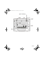
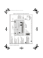
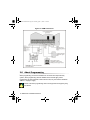
OMNRCV3ES-EI00.fm Page -1 Thursday, April 17, 2003 11:30 AM
Wireless Expansion Module V2.0
OMN-RCV3
Reference & Installation Manual
Stand-Alone System
OMNRCV3ES-EI00.fm Page 0 Thursday, April 17, 2003 11:30 AM
OMNRCV3ES-EI00.fm Page 1 Thursday, April 17, 2003 11:30 AM
Table of Contents
Introduction ...............................................................................................3
What’s New with Version 2.0 ............................................................................. 3
Technical Specifications .................................................................................... 3
System Features ............................................................................................... 4
Installation .................................................................................................4
Location ............................................................................................................. 5
Noise Level Test ................................................................................................ 5
Connections and Mounting ................................................................................ 6
About Programming ...............................................................................10
Programming Methods .................................................................................... 11
Decimal Select Programming ............................................................................. 11
Feature Select Programming.............................................................................. 11
How To Program ............................................................................................. 12
Programming ..........................................................................................12
Set Code Length ............................................................................................. 12
Set Installer Code ............................................................................................ 12
User Parameters ............................................................................................. 13
Assign a User to the Omnia Module (Esprit mode only)..................................... 14
Assign a Remote Control.................................................................................... 14
Program the Remote Control Buttons ................................................................ 15
Remote Control Button PGM Options ............................................................. 17
Delete an Assigned User (Esprit mode only) .................................................. 18
Delete an Assigned Remote Control ............................................................... 18
Programmable Outputs (PGMs) ............................................................18
PGM Connection ............................................................................................. 19
PGM Output Timer .......................................................................................... 19
Panic Alarm Programming ....................................................................20
Panic Output Programming (Esprit mode only) ............................................... 20
Panic Lockout Timer (Esprit mode only) ......................................................... 20
OMNRCV3ES-EI00.fm Page 2 Thursday, April 17, 2003 11:30 AM
Panic Alarm PGM Option (Esprit mode only) ................................................... 21
System Reset ......................................................................................... 22
List of Programming Sections .............................................................. 22
List of Tables
Stand-Alone Programming Sections................................................................
User Parameter Sections.................................................................................
Remote Control Button Options .......................................................................
RC Button PGM Options..................................................................................
PGM Output Timer...........................................................................................
Panic Outputs ..................................................................................................
Panic Lockout Timer ........................................................................................
11
13
16
17
19
20
21
List of Figures
Mounting ............................................................................................................ 7
Connection with an Esprit Control Panel ........................................................... 8
Stand-Alone Connection .................................................................................... 9
PGM Connections............................................................................................ 10
Remote Control Button Identification ............................................................... 15
OMNRCV3ES-EI00.fm Page 3 Thursday, April 17, 2003 11:30 AM
1.0
Introduction
This manual details how to connect, program and operate the Omnia wireless
expansion module when used in conjunction with an Esprit security system or as a
stand-alone system.
When connected to an Esprit security system, the Omnia module functions as an
arm/disarm module, whereby up to eight Omnia remote controls can perform actions
such as remote arming and disarming, communicating panic alarms and activating
programmable outputs (PGMs). In stand-alone mode, the remote controls will only
activate the four on-board PGMs.
1.1 What’s New with Version 2.0
• Functions with Paradox Esprit series control panels
• Functions as a stand-alone module
• 4 on-board programmable outputs (PGMs): Two 5A relay outputs (1 optional)
and two low-current outputs (150mA max.)
• Noise level test
1.2 Technical Specifications
• Di-pole antenna
• Error Correction Algorithm
• Code-Hopping Technology
• Frequency:
433MHz or 868MHz
• Range* (line of sight):
remote controls = 100m (300ft)
• Sensitivity:
-120 dBm
• Current consumption:
50 mA
• Dimensions (no antenna):
15cm H x 16cm L x 3cm W
(6in H x 6.5in L x 1.1in W)
• Operating temperature:
0°C to 49°C (32°F to 120°F)
Omnia 3
OMNRCV3ES-EI00.fm Page 4 Thursday, April 17, 2003 11:30 AM
• PGM outputs:
4 on-board PGM outputs:
one PGM form C relay output
rated at 5A/28Vdc, N.O./N.C. (+1
optional)
two 150mA PGM transistor
outputs
• Programming keypad:
Esprit 636 or 646 LED keypad
• Approvals:
433MHz
868MHz
Compliant to all EU and EFTA
countries except Greece
according to RTT&E directives.
*Not evaluated by UL.
Specifications may change without prior notice.
1.3 System Features
• Auto-Panel Recognition
• Supports up to 8 users
• Supports up to 8 Omnia remote controls
• 4 on-board programmable outputs (PGMs)
• On-board anti-tamper switch
• Stand-alone operation (trigger PGMs only) or in conjunction with an Esprit
control panel (arm/disarm, panic alarms, PGM activation)
• Programming keypad (636, 646) connects directly to the Omnia module
2.0
Installation
The following sections detail how to mount and connect the Omnia module.
4 Reference & Installation Manual
OMNRCV3ES-EI00.fm Page 5 Thursday, April 17, 2003 11:30 AM
2.1 Location
The location of the Omnia module affects its performance. In order to ensure
the best possible signal reception, the following list of location criteria should
be respected whenever possible:
• Select an installation site that is free of obstacles that reflect and absorb
radio frequency (RF) signals, as well as interference that may distort signals.
Avoid installation near or in the path of strong RF fields (i.e. neon lights,
computers), on or near metal objects, circuit breaker boxes, air conditioners,
and heater ducts since they may cause interference and reduce the module’s
sensitivity
• Select a site that is not susceptible to drastic temperature changes
• Mount the Omnia module as high as possible
• Avoid mounting the Omnia module in the basement as the range of the
module is reduced when mounted below ground level. However, if it is
absolutely necessary to mount the module in the basement, mount the
module as high and as close to the underside of the first floor as possible
• Mount the Omnia module on a wall allowing at least 5cm (2in) around the
module to permit adequate ventilation and heat dissipation
For the maximum allowable distance between the control panel and
the Omnia module, refer to Figure 2.2 on page 8.
2.2 Noise Level Test
The Omnia module performs a test on power-up that verifies the noise level in
the surrounding environment. If the environment is too noisy, the module’s RX
LED will illuminate (refer to Figure 2.2 on page 8) and will remain illuminated
until the module is powered up again. In such cases, power down the Omnia
module, change its location, and then power up. Repeat this procedure until
the module’s RX LED no longer illuminates. If all possible mounting locations
have been tested and the environment is still too noisy, be aware that the
wireless system may not function properly.
Omnia 5
OMNRCV3ES-EI00.fm Page 6 Thursday, April 17, 2003 11:30 AM
2.3 Connections and Mounting
1. Using a screwdriver, remove the screw on the Omnia module’s front cover
and then remove the front cover.
2. Firmly screw the antenna into the connector marked ANT on the Omnia
module (refer to Figure 2.1 on page 7).
3. Remove the printed circuit board (PCB) by applying outward pressure to
the mounting clips (refer to Figure 2.1 on page 7) and then lifting the PCB.
4. Using a drill or screwdriver, punch out the four mounting holes on the back
cover (refer to Figure 2.1 on page 7).
5. Align the six orientation holes (refer to Figure 2.1 on page 7) of the PCB
with the six pins on the back cover and snap the PCB into place. If placed
correctly, the antenna will lean directly over the groove in the back cover.
6. Temporarily mount the Omnia module in its proposed location (refer to
section 2.1 on page 5) with masking tape or any other temporary adhesive.
7. If connecting the Omnia module to an Esprit control panel, connect the
module to the control panel in a star or daisy chain configuration (refer to
Figure 2.2 on page 8). When used as a stand-alone module, connect the
module using an external 12Vdc power supply that is equipped with a
backup battery connector (refer to Figure 2.3 on page 9).
8. Verify the environment noise surrounding the Omnia module (refer to
section 2.2 on page 5).
9. Assign the users and/or remote controls, and then program the remote
control buttons (refer to section 4.3 on page 13).
10. Test the location of the Omnia module by performing an action using an
assigned remote control from a typical distance and location.
11. Permanently mount the Omnia module.
Do not cut, bend, or alter the antenna. Ensure that the electrical wires
do not cross over the antenna when connected.
6 Reference & Installation Manual
OMNRCV3ES-EI00.fm Page 7 Thursday, April 17, 2003 11:30 AM
Figure 2.1: Mounting
Omnia 7
OMNRCV3ES-EI00.fm Page 8 Thursday, April 17, 2003 11:30 AM
Refer to Figure 2.4 on
page 10 for PGM
connections.
Figure 2.2: Connection with an Esprit Control Panel
8 Reference & Installation Manual
OMNRCV3ES-EI00.fm Page 9 Thursday, April 17, 2003 11:30 AM
Refer to Figure 2.4 on
page 10 for PGM
connections.
Figure 2.3: Stand-Alone Connection
Omnia 9
OMNRCV3ES-EI00.fm Page 10 Thursday, April 17, 2003 11:30 AM
Figure 2.4: PGM Connections
3.0
About Programming
When programming an Omnia module that is connected to an Esprit security
system, all the programming sections detailed in this manual apply. When
programming an Omnia module in stand-alone mode, only the sections detailed in
Table 3.1 on page 11 apply.
Please note that a programming section is empty when the keypad’s [2ND]
key flashes.
10 Reference & Installation Manual
OMNRCV3ES-EI00.fm Page 11 Thursday, April 17, 2003 11:30 AM
Table 3.1: Stand-Alone Programming Sections
Section
[00]
[09] to [16]
[17] to [24]: options [4], [5], [6], [7]
[27] to [30]
[31] to [34]
[35]: option [1]
3.1 Programming Methods
When connected to an Esprit security system, or in stand-alone mode, the
Omnia module is programmed using an Esprit 636 or 646 LED keypad. The
Omnia module is programmed using a combination of the Decimal Select and
Feature Select Programming methods.
3.1.1 DECIMAL SELECT PROGRAMMING
Sections [25] to [30] represent one feature and keys [0] to [8] represent
a specific setting for the feature. Unlike Feature Select Programming
(refer to section 3.1.2), only one setting can be selected. When using
Esprit 636 or 646 keypads, the keys display the selected setting by
illuminating the corresponding key. Press the key representing the
desired setting and then press [ENTER] to save.
3.1.2 FEATURE SELECT PROGRAMMING
In sections [17] to [24] and [31] to [35], keys [1] to [8] correspond to a
specific feature or option. When using Esprit 636 or 646 keypads, the
keys display the ON/OFF status of the features by illuminating when the
feature is ON. Press the keys corresponding to the desired options and
then press [ENTER] to save.
Omnia 11
OMNRCV3ES-EI00.fm Page 12 Thursday, April 17, 2003 11:30 AM
3.2 How To Program
How to program.
1. Press Omnia’s “PROGRAM” button (refer to Figure 2.2 on page 8).
2. Press the [ENTER] key.
3. Enter [INSTALLER CODE] (default code: 757575)
4. Enter the desired [SECTION NUMBER].
5. Enter the required data.
6. Press [ENTER].
4.0
Programming
4.1 Set Code Length
SECTION
[35]: OPTION [1]
Set the Omnia module to accept either four- or six-digit user and installer
codes.
How to set the access code length.
In step 4 in section 3.2 on page 12:
1. Enter section [35].
2. Enable or disable option [1].
Option [1] OFF = 4-digit codes
Option [1] ON = 6-digit codes (default)
3. Press [ENTER].
This option must be set to the same setting as in the Esprit control
panel (address 088, key [9]).
4.2 Set Installer Code
SECTION
[00]
The installer code (default: 757575) allows a user to program all the functions
and features pertaining to the Omnia system. The installer code can be either
four- or six-digits in length (refer to section 4.1 on page 12) and each digit can
be any value between zero and nine.
12 Reference & Installation Manual
OMNRCV3ES-EI00.fm Page 13 Thursday, April 17, 2003 11:30 AM
How to set the installer code.
In step 4 in section 3.2 on page 12:
1. Enter section [00].
2. Enter the [NEW INSTALLER CODE].
3. Press [ENTER].
4.3 User Parameters
The Omnia system supports up to eight users and eight remote controls. When
connected to an Esprit control panel, each of the following user parameters
must be performed for every Omnia user. In stand-alone mode, assigning a
user to the Omnia module does not apply. Refer to Table 4.1 for the
relationship between the user parameter sections.
• Assign the user to the Omnia module
• Assign a remote control
• Define the remote control buttons
Table 4.1: User Parameter Sections
User # / RC #
Assign User To
Module (Esprit
mode only)
Assign Remote
Control
Define Remote
Control Buttons
1
[01]
[09]
[17]
2
[02]
[10]
[18]
3
[03]
[11]
[19]
4
[04]
[12]
[20]
5
[05]
[13]
[21]
6
[06]
[14]
[22]
7
[07]
[15]
[23]
8
[08]
[16]
[24]
Omnia 13
OMNRCV3ES-EI00.fm Page 14 Thursday, April 17, 2003 11:30 AM
4.3.1 ASSIGN A USER TO THE OMNIA MODULE (ESPRIT MODE ONLY)
SECTIONS
[01] TO [08]
When a user presses a remote control’s button, Omnia transmits the
corresponding user code to the Esprit control panel. The control panel
must receive a valid user code in order to process the action. Sections
[01] to [08] represent users 1 to 8 respectively (refer to Table 4.1 on
page 13).
How to assign a user to the Omnia module.
In step 4 in section 3.2 on page 12:
1. Enter a section number between [01] and [08].
2. Enter the [USER CODE].
3. Press [ENTER].
The user code entered in sections [01] to [08] must match the
same user’s code programmed in the Esprit control panel.
4.3.2 ASSIGN A REMOTE CONTROL
SECTIONS
[09] TO [16]
When connected to an Esprit control panel, assign up to eight Omnia
remote controls to users in the Esprit security system, whereby
sections [09] to [16] correspond to users 1 to 8 respectively (refer to
Table 4.1 on page 13). Each time a remote control’s button is pressed,
it transmits its RF code to the Omnia module, which contains the
corresponding user information. In stand-alone mode, assign up to
eight remote controls to the module, whereby sections [09] to [16]
represent remote controls 1 to 8 (refer to Table 4.1 on page 13).
How to assign a remote control.
In step 4 in section 3.2 on page 12:
1. Enter a section number between [09] and [16].
2. Press [ENTER]. The keypad’s “Ready” and “Arm” lights will
illuminate.
3. Press any button on the remote control twice. The keypad will
beep twice to confirm.
4. Press [ENTER].
14 Reference & Installation Manual
OMNRCV3ES-EI00.fm Page 15 Thursday, April 17, 2003 11:30 AM
If a rejection beep is heard (“Beeeeeeeeeeeep”), the remote
control assignment was not successful. The remote control may
already be assigned.
4.3.3 PROGRAM THE REMOTE CONTROL BUTTONS
SECTIONS
[17] TO [24]
Sections [17] to [24] correspond to remote controls 1 to 8 (refer to
Table 4.1 on page 13). Program the remote control buttons to perform a
specific action. Enable or disable options [1] to [8] (refer to Table 4.2 on
page 16) by pressing the corresponding keypad key.
How to program a remote control’s buttons.
In step 4 in section 3.2 on page 12:
1. Enter a section number between [17] and [24].
2. Enable or disable options [1] to [8] (refer to Table 4.2 on
page 16).
3. Press [ENTER].
Figure 4.1: Remote Control Button Identification
Omnia 15
OMNRCV3ES-EI00.fm Page 16 Thursday, April 17, 2003 11:30 AM
Table 4.2: Remote Control Button Options
RC Button Arming Options (Esprit mode only)
Key [1]
Key [2]
Key [3]
Off
Off
Off
No Arm or Disarm
Definition
On
Off
Off
Button A = Regular Arm
Off
On
Off
Button B = Regular Arm
On
On
Off
Button A = Regular Arm
Button B = Regular Arm
Off
Off
On
Button A = Instant Arm
On
Off
On
Button A = Instant Arm
Button B = Stay Arm
Off
On
On
Button A = Regular Arm
Button B = Stay Arm
On
On
On
Button A = Stay Arm
RC Button PGM Enabling (refer to section 4.4 on page 17)
Key [4] OFF = Disabled
Key [4] ON = Button A PGM Enabled (default)
Key [5] OFF = Disabled
Key [5] ON = Button B PGM Enabled (default)
Key [6] OFF = Disabled
Key [6] ON = Button C PGM Enabled (default)
Key [7] OFF = Disabled
Key [7] ON = Button D PGM Enabled (default)
RC Button Panic Options (Esprit mode only)
Key [8] OFF Panic Disabled
Key [8] ON Panic Enabled (default)
Only arming functions were investigated by UL.
16 Reference & Installation Manual
OMNRCV3ES-EI00.fm Page 17 Thursday, April 17, 2003 11:30 AM
4.4 Remote Control Button PGM Options
SECTIONS
[31] TO [34]: OPTIONS [1] TO [4]
If a remote control’s buttons have the PGM feature enabled (refer to Table 4.2
on page 16), this feature determines which PGM outputs the respective
buttons will activate. Each remote control button can be programmed to
activate a different PGM. Sections [31] to [34] correspond to remote control
buttons A to D respectively (refer to Figure 4.1 on page 15). In the section
corresponding to the desired remote control button, select which PGM output
will be triggered by enabling and disabling options [1] to [4] (refer to Table 4.3
on page 17).
This feature is a global feature, therefore if button A is programmed to
toggle the PGM 3 output, then button A on all remote controls will
toggle the PGM 3 output.
How to set the RC button PGM options.
In step 4 in section 3.2 on page 12:
1. Enter a section number between [31] and [34].
2. Enable or disable options [1] to [4] (refer to Table 4.3).
3. Press [ENTER].
Table 4.3: RC Button PGM Options
Key [1] OFF = Disabled
Key [1] ON = Activate PGM 1 output
Key [2] OFF = Disabled
Key [2] ON = Activate PGM 2 output
Key [3] OFF = Disabled
Key [3] ON = Activate PGM 3 output
Key [4] OFF = Disabled
Key [4] ON = Activate PGM 4 output
Omnia 17
OMNRCV3ES-EI00.fm Page 18 Thursday, April 17, 2003 11:30 AM
4.5 Delete an Assigned User (Esprit mode only)
SECTIONS
[01] TO [08]
Sections [01] to [08] correspond to users 1 to 8 respectively.
How to delete an assigned user.
In step 4 in section 3.2 on page 12:
1. Enter a section number between [01] and [08].
2. Press [2ND].
3. Press [ENTER].
4.6 Delete an Assigned Remote Control
SECTIONS
[09] TO [16]
Sections [09] to [16] correspond to remote controls 1 to 8 respectively.
How to delete an assigned remote control.
In step 4 in section 3.2 on page 12:
1. Enter a section number between [09] and [16].
2. Press [2ND].
3. Press [ENTER].
5.0
Programmable Outputs (PGMs)
The Omnia module provides four on-board PGM outputs, which can be used for a
variety of home/office automation applications such as opening a garage door when
a remote control button is pressed. For the PGM locations, refer to Figure 2.4 on
page 10.
• PGM 1 and PGM 2: Two 150mA PGM transistor outputs
• PGM 3: Form “C” relay output rated at 5A/28Vdc, N.O./N.C
• PGM 4: Optional form “C” relay output rated at 5A/28Vdc, N.O./N.C
18 Reference & Installation Manual
OMNRCV3ES-EI00.fm Page 19 Thursday, April 17, 2003 11:30 AM
5.1 PGM Connection
The PGMs are connected as detailed in Figure 2.4 on page 10.
5.2 PGM Output Timer
SECTIONS
[27] TO [30]
This feature determines whether an activated PGM will toggle back to its
original state after a specified time period has elapsed or when toggled
(latched) manually. Each PGM output can be programmed with a unique
output timer. Sections [27] to [30] correspond to PGM 1 to PGM 4 respectively.
In the section corresponding to the desired PGM, enable one of the options
from [0] to [8] (refer to Table 5.1 on page 19) by pressing the corresponding
keypad key.
How to set the PGM output timer.
In step 4 in section 3.2 on page 12:
1. Enter a section number between [27] and [30].
2. Enable only one option from [0] to [8] (refer to Table 5.1).
3. Press [ENTER].
Table 5.1: PGM Output Timer
Key [0] ON
= Latched
Key [1] ON
= 1 second
Key [2] ON
= 5 seconds (default)
Key [3] ON
= 10 seconds
Key [4] ON
= 20 seconds
Key [5] ON
= 40 seconds
Key [6] ON
= 60 seconds
Key [7] ON
= 2 minutes
Key [8] ON
= 4 minutes
Omnia 19
OMNRCV3ES-EI00.fm Page 20 Thursday, April 17, 2003 11:30 AM
6.0
Panic Alarm Programming
If the panic alarm feature is enabled for the remote control (refer to section 4.3.3 on
page 15), pressing buttons A and B, or C and D (refer to Figure 4.1 on page 15)
simultaneously will generate a panic alarm.
6.1 Panic Output Programming (Esprit mode only)
SECTION
[25]: OPTIONS [0] TO [4]
When a remote control activates a panic alarm, the Omnia module can be
programmed to activate one of the four on-board PGM outputs. Enable one of
the options from [0] to [4] (refer to Table 6.1 on page 20) by pressing the
corresponding keypad key.
How to program the panic outputs.
In step 4 in section 3.2 on page 12:
1. Enter section [25].
2. Enable only one option from [0] to [4] (refer to Table 6.1).
3. Press [ENTER].
Table 6.1: Panic Outputs
Key [0] ON
= No PGM output on panic alarm
Key [1] ON
= Toggle PGM 1 on panic alarm
Key [2] ON
= Toggle PGM 2 on panic alarm
Key [3] ON
= Toggle PGM 3 on panic alarm (default)
Key [4] ON
= Toggle PGM 4 on panic alarm
6.2 Panic Lockout Timer (Esprit mode only)
SECTION
[26]: OPTIONS [0] TO [4]
When a remote control activates a panic alarm, the Omnia module can be
programmed to ignore any incoming remote control (RF) signals for a specified
time period. Enable one option from [0] to [4] (refer to Table 6.2 on page 21) by
pressing the corresponding keypad key.
20 Reference & Installation Manual
OMNRCV3ES-EI00.fm Page 21 Thursday, April 17, 2003 11:30 AM
How to set the panic lockout timer.
In step 4 in section 3.2 on page 12:
1. Enter section [26].
2. Enable only one option from [0] to [4] (refer to Table 6.2).
3. Press [ENTER].
Table 6.2: Panic Lockout Timer
Key [0] ON
= No RF signal lockout on panic alarm (default)
Key [1] ON
= 30-second RF signal lockout on panic alarm
Key [2] ON
= 60-second RF signal lockout on panic alarm
Key [3] ON
= 90-second RF signal lockout on panic alarm
Key [4] ON
= 120-second RF signal lockout on panic alarm
6.3 Panic Alarm PGM Option (Esprit mode only)
SECTION
[35]: OPTION [2]
When a remote control activates a panic alarm, the Omnia module can either
toggle only the remote control’s enabled PGM output (refer to section 6.1 on
page 20) or toggle the remote control’s enabled PGM output and send a panic
alarm code to the Esprit control panel.
How to set the panic alarm PGM option.
In step 4 in section 3.2 on page 12:
1. Enter section [35].
2. Enable or disable option [2].
Option [2] OFF = Toggle the enabled PGM output only.
Option [2] ON = Toggle the enabled PGM output and send a
panic alarm code.
3. Press [ENTER].
Omnia 21
OMNRCV3ES-EI00.fm Page 22 Thursday, April 17, 2003 11:30 AM
7.0
System Reset
Performing a system reset will reset all the Omnia module sections to their factory
default settings.
How to reset the Omnia module.
1. Remove the power connections from the Omnia module (“RED” and
“BLK”).
2. Press and hold the Omnia module’s “PROGRAM” button (refer to Figure 2.2
on page 8) while reconnecting the power connections to the Omnia
module. The keypad will beep.
3. Wait approximately 1 second and release the “PROGRAM” button. The
Omnia module’s red LED will flash quickly for approximately 5 seconds.
8.0
List of Programming Sections
Section
[00]
Description
Set the installer code
[01] to [08]
Assign a user to the Omnia module
[09] to [16]
• Assign a remote control
• Delete an assigned remote control
[17] to [24]
Remote Control Button Programming
Options [1] to [3]: Remote control arming options
Option [4]: Enable button A PGM
Option [5]: Enable button B PGM
Option [6]: Enable button C PGM
Option [7]: Enable button D PGM
Option [8]: Enable Panic
[25]
Panic Alarm Outputs
Option [0]: No PGM output on panic alarm
Option [1]: Toggle PGM 1 on panic alarm
Option [2]: Toggle PGM 2 on panic alarm
Option [3]: Toggle PGM 3 on panic alarm
Option [4]: Toggle PGM 4 on panic alarm
22 Reference & Installation Manual
OMNRCV3ES-EI00.fm Page 23 Thursday, April 17, 2003 11:30 AM
Section
[26]
Description
Panic Alarm Lockout Timer
Option [0]: No RF signal lockout on panic alarm
Option [1]: 30-second RF signal lockout on panic alarm
Option [2]: 60-second RF signal lockout on panic alarm
Option [3]: 90-second RF signal lockout on panic alarm
Option [4]: 120-second RF signal lockout on panic alarm
[27] to [30]
PGM Output Timers
Option [0]: Latched
Option [1]: 1 second
Option [2]: 5 seconds
Option [3]: 10 seconds
Option [4]: 20 seconds
Option [5]: 40 seconds
Option [6]: 60 seconds
Option [7]: 2 minutes
Option [8]: 4 minutes
[31] to [34]
RC Button PGM Options
Option [1]: Activate PGM 1 output
Option [2]: Activate PGM 2 output
Option [3]: Activate PGM 3 output
Option [4]: Activate PGM 4 output
[35]
Option [1]: Set the access code length
Option [2]: Set the panic alarm PGM option
Omnia 23
OMNRCV3ES-EI00.fm Page 24 Thursday, April 17, 2003 11:30 AM
Warranty
The Seller warrants its products to be free from defects in materials and
workmanship under normal use for a period of one year (unless otherwise
indicated). Except as specifically stated herein, all express or implied warranties
whatsoever, statutory or otherwise, including without limitation, any implied warranty
of merchantability and fitness for a particular purpose, are expressly excluded.
Because Seller does not install or connect the products and because the products
may be used in conjunction with products not manufactured by Seller, Seller cannot
guarantee the performance of the security system. Seller obligation and liability
under this warranty is expressly limited to repairing or replacing, at Seller's option,
any product not meeting the specifications. In no event shall the Seller be liable to
the buyer or any other person for any loss or damages whether direct or indirect or
consequential or incidental, including without limitation, any damages for lost profits,
stolen goods, or claims by any other party caused by defective goods or otherwise
arising from the improper, incorrect or otherwise faulty installation or use of the
merchandise sold.
For 433MHz Omnia remote controls:
FCC ID: KDYOMNRCT1
Canada: 2438A-OMNRCT1
The OMN-RCT1 complies with part 15 of the FCC rules. Operation is subject to the
following two conditions: (1) This device may not cause harmful interference, and (2)
This device must accept any interference received, including interference that may
cause undesired operation.
Esprit and Omnia are trademarks of Paradox Security Systems.
© 2003 Paradox Security Systems.
24 Reference & Installation Manual
OMNRCV3ES-EI00.fm Page 25 Thursday, April 17, 2003 11:30 AM
OMNRCV3ES-EI00.fm Page 26 Thursday, April 17, 2003 11:30 AM
PRINTED IN CANADA 04/2003
OMNRCV3ES-EI00