1
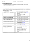
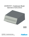
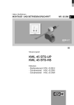
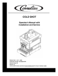
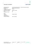
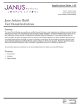
NELSON
Nelson EcoVent Recirculator
NELSON
®
®
EcoVent
Recirculator
Installation
Manual
SM-337
TM
©Fleetguard
All Rights Reserved
Printed in U.S.A.
LT35014 2/03
Q55916
NELSON
Nelson EcoVent Recirculator
NELSON
®
Nelson EcoVent Recirculator
®
Maintenance Instructions
Whenever the manometer shows a reading of 1.5" H2O positive pressure, you must replace the
EcoVent filter element.
1. With the engine shut off and cooled, remove the EcoVent’s cover clamp, cover and cover
gasket.
2. Remove the hex nut, element seal plate and element.
3. Replace the element with the proper new element. Inspect the cover gasket and grommet on
the element seal plate and replace if cut, damaged or swollen.
4. Replace the parts in the same order in which you removed them.
5. Start the engine and check the manometer. If it is not showing a 0" to 0.3" H2O positive
pressure reading, follow the adjustment instructions on pages 9 and 10 to adjust the air flow.
Hex Nut
Step 1
Cover Clamp
Element Seal Plate
Cover Gasket
Element
Cover
Grommet
Step 2
Figure 9 • Parts to be removed during maintenance.
Parts List
Description
EcoVent
Filter Element
Cover Gasket
Grommet
Nut
2
93196A
Part Number
93195A
93194A
93192A
88468A
Q58510
Q58521
Q53714
88467A
Q58510
Q58521
Q53714
88465A
Q58403
Q58521
Q01428
88365A
Q58403
Q58521
Q01428
NELSON
NELSON
Nelson EcoVent Recirculator
About This Product
Use 3/8" I.D.
clear flexible
tubing and
clamp.
Nelson’s EcoVent Recirculator removes 99.9% of oil mist and airborne particles coming from the
engine crankcase breather vent. Because the separation of crankcase fumes and oil is
accomplished by means of a static absorbent filter, there are no moving parts. There is also no
need for periodic cleaning—you only have to change the filter element!
Open to
atmosphere.
To Ecovent
manometer
gauge
connection.
Fill the U-tube
gauge with
the red gauge
oil supplied.
Install the
gauge in a
vertical plumb
position.
Adjust the
U-tube to zero
with both
connections
vented to
atmosphere.
8
7
6
5
4
3
2
1
0
1
2
3
4
5
6
7
8
Gauge
reads in
inches of
water.
Gauge
reading
with new
element
must not
exceed 0
to 0.3
inches of
water at
normal
engine
operating
speed.
Figure 7 • U-tube Manometer Gauge Reading
With New Filter Element
Nelson EcoVent Recirculator
®
®
To properly
read the
U-tube gauge,
you must add
the readings
on both sides
of the U-tube
gauge.
Example: the
gauge at the
right shows
a gauge
reading of 1.5
inches of
water.
0.75 + 0.75
=1.5
8
7
6
5
4
3
2
1
0
1
2
3
4
5
6
7
8
The
EcoVent
filter element
must be
changed
when the
gauge
reading
reaches a
maximum of
1.5 inches of
water.
The EcoVent Recirculator makes it possible to duct clean blowby fumes into the air cleaner, for a
completely closed system, thereby removing 100% of the blowby mists and gases from the
atmosphere without danger to the engine. This provides for a cleaner, healthier and safer
environment while reducing engine room maintenance costs.
Figure 8 • U-tube Manometer Gauge Reading
At Filter Element Changeout
Operating Instructions
Once you have installed and adjusted the EcoVent, operating instructions are very simple:
•
Monitor the reading on the manometer. When it reaches a reading of 1.5" H2O positive
pressure (see figure 8) replace the EcoVent element, as shown in the Maintenance Section.
•
If you are not returning the oil to the engine, drain the oil from the EcoVent as needed.
Figure 1 • The EcoVent Recirculator attached to an engine.
!
WARNING
Read the entire Service Manual before attempting the installation!
NELSON
NELSON
Nelson EcoVent Recirculator
®
Nelson EcoVent Recirculator
®
Installation
Manometer
Gauge
Connection
You can install the EcoVent Recircualtor in one of two ways: with the outlet connected to the
engine’s air inlet flow before the air filter (Option 1) or directly to the engine’s air intake
ducting (Option 2). Please follow the instructions for your specific situation.
Engine Crankcase Breather Vent
to EcoVent Inlet Connection
Engine Air
Intake Filter
Control Valve
Option 1: Connecting the Outlet to the Air Inlet Flow
See Figures 2 or 3 for an illustration of a correctly installed EcoVent Recirculator.
☞ NOTE
Drain
Valve
In all cases, you can substitute a rigid pipe where the instructions call for a heat-resistant
hose.
AIN
DR IL
O
1. Use the two mounting brackets we have provided to mount the EcoVent on or adjacent to
the engine. You must mount the EcoVent horizontally and above the engine crankcase oil
level.
2. Follow the manufacturer’s instructions to attach the U-tube manometer gauge (which we
have supplied) to the manometer gauge connection on the EcoVent.
3. Attach the proper size of heat-resistant hose to the EcoVent’s inlet connection and secure
with a hose clamp.
4. Attach the end of the hose used in Step 3 to the engine’s crankcase breather vent tube and
secure with a hose clamp.
EcoVent Outlet
Connected Directly
to Air Intake Ducting
Figure 5 • Completed installation, showing oil being drained.
Adjusting the Air Flow
If, at normal engine operating speed the U-tube manometer gauge does not show a 0" to 0.3" H2O
positive pressure reading, perform the proper adjustment to correct it.
1. If the EcoVent’s outlet hose is connected near the air inlet flow, move the open end of the hose
into or out of the flow until the manometer shows the proper reading, then secure it with a
hose clamp.
5. Attach another length of heat-resistant hose to the EcoVent’s outlet connection and secure
with a hose clamp.
6. Attach the end of the hose used in Step 5 to the engine’s air intake filter near the air inlet
flow and secure with a hose clamp.
!
CAUTION
If you connect the EcoVent’s outlet hose to the air inlet flow before the air intake filter,
position the end of the hose so that the vacuum created by the air flow produces a 0" to
0.3" H2O positive pressure reading on the U-tube manometer. See figure 7. At normal
engine operating speed a new EcoVent unit must not have more than 0.3" H2O positive
pressure!
Air Flow
Air Cleaner
Hood
Hose
to EcoVent
Outlet
Figure 6 • Move the outlet hose into or out of the air flow to adjust the pressure.
2. If the EcoVent’s outlet hose is connected directly to the air intake ducting, adjust the control
valve on the outlet hose until the manometer shows the proper reading.
Once the initial proper gauge reading has been established, do not adjust the location of the
hose or the control valve during the life of the EcoVent element.
NELSON
NELSON
Nelson EcoVent Recirculator
Manometer
Gauge
Connection
Engine Crankcase Breather Vent
to EcoVent Inlet Connection
Engine Air
Intake Filter
Control Valve
If You Are Returning the Oil to the Engine
If the engine does not use natural gas or fuels that contain sulfur or halogen chemicals, you can
return the oil collected directly to the engine oil sump.
!
EcoVent Outlet
Connected Directly
to Air Intake Ducting
Drain Line Must be
Below Oil Level
Figure 4 • Completed installation, showing the oil being returned to the engine.
Nelson EcoVent Recirculator
®
®
CAUTION
If the engine uses natural gas or fuels that contain sulfur or halogen chemicals, do not
return the collected oil to the engine. If this applies to your installation, please turn to the
next section for more information.
7. Connect a drain tube to the drain port on the underside of the EcoVent.
8. Place the other end of the drain tube into the engine oil sump, below the oil level line.
Manometer
Gauge
Connection
Engine Crankcase Breather Vent
to EcoVent Inlet Connection
Engine Air
Intake Filter
If the Engine Uses Natural Gas or Fuels Containing Sulfur or
Halogen Chemicals
7. Connect a drain tube to the drain port on the underside of the EcoVent.
8. Connect a drain valve to the drain tube.
9. Place an oil reservoir at the end of the drain tube. How often you drain the EcoVent depends
upon the amount of oil in the engine crankcase fumes and the condition of the engine.
10. Check the adjustment of the EcoVent by starting the engine and running it at normal
operating speed. The U-tube manometer gauge should have a 0" to 0.3" H2O positive
pressure reading. If not, adjust the air flow until it does. See the Section entitled Adjusting
the Air Flow for more information.
EcoVent Outlet
Connected
to Engine Air
Inlet Flow
Drain Line Must Be
Below Oil Level
Figure 2 • Completed installation, showing the oil being returned to the engine.
9. Check the adjustment of the EcoVent by starting the engine and running it at normal operating
speed. The U-tube manometer gauge should have a 0" to 0.3" H2O positive pressure reading.
See figure 7. If not, adjust the air flow until it does. See the Section entitled Adjusting the Air
Flow for more information.
If the Engine Uses Natural Gas or Fuels Containing Sulfur or
Halogen Chemicals
7. Connect a drain tube to the drain port on the underside of the EcoVent.
8. Connect a drain valve to the drain tube.
NELSON
NELSON
Nelson EcoVent Recirculator
9. Place an oil reservoir at the end of the drain tube. How often you drain the EcoVent depends
upon the amount of oil in the engine crankcase fumes and the condition of the engine.
Manometer
Gauge
Connection
®
®
Engine Crankcase Breather Vent
to EcoVent Inlet Connection
Engine Air
Intake Filter
Nelson EcoVent Recirculator
3. Attach the proper size of heat-resistant hose to the EcoVent’s inlet connection and secure with
a hose clamp.
4. Attach the end of the hose used in Step 3 to the engine’s crankcase breather vent tube and
secure with a hose clamp.
5. Attach another length of heat-resistant hose to the EcoVent’s outlet connection and secure with
a hose clamp.
Drain
Valve
EcoVent Outlet
Connected
to Engine Air
Inlet Flow
AIN
DR IL
O
6. Install a control valve on the hose used in Step 5, then attach the end of the hose directly to the
engine’s air intake ducting and secure with a hose clamp. You can attach the hose either before
or after the engine’s air filter. The control valve is used to regulate the maximum 0" to 0.3"
H2O positive pressure reading for the new EcoVent element. See figure 7. Do not adjust this
valve after you have properly set it to achieve the 0" to 0.3" H2O positive pressure reading.
!
Figure 3 • Completed installation, showing oil being drained to an oil reservoir.
10. Check the adjustment of the EcoVent by starting the engine and running it at normal
operating speed. The U-tube manometer gauge should have a 0" to 0.3" H2O positive
pressure reading. If not, adjust the air flow until it does. See the Section entitled Adjusting
the Air Flow for more information.
Option 2: Connecting the Outlet Directly to the Air
Intake Ducting
See Figures 4 or 5 for an illustration of a correctly installed EcoVent Recirculator.
☞
NOTE
In all cases, you can substitute a rigid pipe where the instructions call for a heat-resistant
hose.
1. Use the two mounting brackets we have provided to mount the EcoVent on or adjacent to
the engine. You must mount the EcoVent horizontally and above the engine crankcase oil
level.
2. Follow the manufacturer’s instructions to attach the U-tube manometer gauge (which we
have supplied) to the manometer gauge connection on the EcoVent.
CAUTION
With the EcoVent’s outlet hose connected, along with the control valve, directly to the
engine air intake ducting, simply adjust the control valve so that the vacuum created by the
air flow is 0" to 0.3" H2O positive pressure reading on the U-tube manometer guage. See
figure 7. At normal operating speed a new EcoVent unit must not have more than 0.3" H2O
positive pressure!
If You Are Returning the Oil to the Engine
If the engine does not use natural gas or fuels that contain sulfur or halogen chemicals, you can
return the oil collected directly to the engine oil sump.
!
CAUTION
If the engine uses natural gas or fuels that contain sulfur or halogen chemicals, do not
return the collected oil to the engine. Please turn to the next section for information on
completing the installation if this applies to your installation.
7. Connect a drain tube to the drain port on the underside of the EcoVent.
8. Locate the other end of the drain tube into the engine oil sump, below the oil level line.
9. Check the adjustment of the EcoVent by starting the engine and running it at normal operating
speed. The U-tube manometer gauge should have a 0" to 0.3" H2O positive pressure reading.
If not, adjust the air flow until it does. See the Section entitled Adjusting the Air Flow for
more information.