1
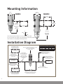
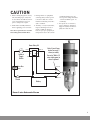
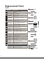
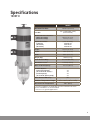
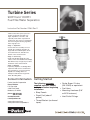
Turbine Series
900FH and 1000FH
Fuel Filter/Water Separators
Instruction Part Number 12960 Rev D
Turbine Series filters protect precision
engine components from dirt, rust,
algae, asphaltines, varnishes, and
especially water, which is prevalent in
engine fuels. They remove contaminants
from fuel using the following legendary
three stage process:
Stage 1 - Separation
As fuel enters the assembly, it moves
through the centrifuge and spins off
large solids and water droplets, which
are heavier than fuel, and fall to the
bottom of the collection bowl.
Stage 2 - Coalescing
Small water droplets bead-up on the
surface of the conical baffle and cartridge
filter. When heavy enough, they too fall to
the bottom of the collection bowl.
Stage 3 - Filtration
Proprietary Aquabloc®II cartridge filters
repel water and remove contaminants
from fuel down to 2 micron (nominal).
Aquabloc®II cartridge filters are
waterproof and effective longer than
water absorbing filters.
Contact Information Getting Started
• Parker Super O-Lube
(RK 31605) or equivalent.
Parker Hannifin Corporation
Racor Division
P.O. Box 3208
3400 Finch Road
Modesto, CA 95353
The following customer
supplied materials should
be on hand before beginning
installation.
phone 800 344 3286
209 521 7860
fax 209 529 3278
[email protected]
• Shop Towels.
• Mounting Hardware (3/8"
or M10 fasteners).
• Diesel Fuel (about 1
gallon).
• Inlet/Outlet Fittings.
www.parker.com/racor
www.parker.com/racorproducts
• Thread Sealant (no thread
tapes).
• Fuel Hose.
Mounting Information
5.8 in.
(14.7 cm)
5.8 in.
(14.7 cm)
900FH
1000FH
4.5 in
(11.4 cm)
11.0 in
(27.9 cm)
Adjustable to
13.5 in
(34.3 cm)
5.0 in
(12.7 cm)
4.5 in
(11.4 cm)
10.9 in
(27.7 cm)
V
10°
10°
Adjustable
by ±2.1 in.
(5.3 cm)
90°
Note: Mount the filter assembly as close to vertical (V) as possible.
Do not exceed 10° from vertical or the assembly may not function properly.
Note: Fastener size 3/8" (M10) for Mounting brackets.
Installation Diagram
Fuel Tanks Above Filter
Do not exceed 39’ (11.9m)
of head feet or 15 PSI.
Fuel Tank
(Pressure Side Installation)
A shut-off valve is
recommended when the
fuel tank is mounted higher
than the filter
Optional Bypass Installation and Operation
Maintain a clearance above the filter assembly
of 5 in. (12.7 cm) (900FH),
and 10 in. (25.4 cm) (1000FH)
for filter removal.
2
Open
Closed
3
Closed
Open
Suction (vacuum) Side:
Primary (first) filter - use 30 micron.
If it is the only filter in the system,
use 2 or 10 micron.
Engine
Valve 1
Valve 2
Install a check valve
(with light or no restriction)
when tank is lower than filter
to maintain prime.
Fuel transfer pump
(IDEAL vacuum side installation)
Fuel Tank
(Vacuum Side Installation)
Valve 3
2
1
Open
Closed
Optional Vacuum Gauge:
Helps in monitoring system restriction
and filter element life.
Pressure Side:
Fuel transfer pump not to
exceed maximum PSI
or flow rate of filter.
Not ideal - pumps emulsify
water hindering filter
performance.
Fuel Tank
(Ideal Vacuum
Side Installation)
Fuel Tank Below Filter
Do not exceed 5’ (1.5m) of lift
or 4 inches of mercury (inHg)
of inlet piping restrictions
(allows user to service filter without shutting down engine.)
Valves
Unit On-line
Unit Off-line
Maintain a service clearance below
filter assembly of at least 2 in. (5.1 cm)
for draining and servicing bowl.
Installation Instructions
Adjustable, one-piece clamptype mounting brackets (with
grade 5 fasteners) are included
for ensured durability. The
900FH uses one mounting
bracket and 1000FH uses two
mounting brackets, both can be
adjusted for a secure fit.
Before Installation
Positioning Filter
• D
O NOT smoke or allow open
flames near the installation.
• I nstall Turbine Series filter on
vacuum side of fuel transfer
pump for optimum water
separating efficiency.
Installing Filter
Note: See installation diagram.
• K
eep fuel line restrictions
to a minimum. Locate filter
assembly between horizontal
planes of bottom of fuel tank
and inlet of fuel pump, if
possible. If filter is installed
in an application where the
fuel tank is higher than the
filter, a shut-off valve must be
installed between tank and
filter assembly INLET. This
will be used when servicing
replacement filter.
• O
btain good ventilation and
lighting.
• M
aintain a safe working
environment.
• The engine must be off for
installation.
• Completely remove any
vacuum side filters in fuel
line between fuel tank and
fuel pump. This is where filter
assembly will be mounted.
Leaving these filters in place
will add to the fuel line
restriction. Filter heads cast
into engine, or that are nonremovable, or hard piped
should be serviced with a new
filter and left in place.
• Keep fuel flow restriction
values to a minimum. Always
use maximum size fuel hose
possible. Do not make sharp
bends with flexible fuel hose
as kinks may occur. Avoid use
of two 45° elbow fittings where
one 90° elbow will work.
• W
hen routing hose, avoid
surfaces that move, have sharp
edges, or get hot (such as
exhaust piping).
Priming
Instructions
1. R
emove T-handle and lid from
top of filter.
2. Fill filter with clean fuel.
3. L
ubricate lid gasket and
T-handle O-ring with clean fuel
or motor oil.
4. R
eplace lid and T-handle and
tighten snugly by hand
only - do not use tools.
5. I f applicable, refer to
equipment Operator’s Service
Manual to complete fuel
priming procedure.
6. S
tart engine and check for
fuel system leaks. Correct as
necessary with engine off and
pressure relieved from filter
assembly.
Service Instructions
Draining Water
Frequency of water draining is
determined by the contamination
level of fuel. Inspect or drain
collection bowl of water daily or as
necessary. Collection bowl must
be drained before contaminants
reach the top of the turbine or
when Water Detection Module
(optional) indicates a drain is
required.
Vacuum Side
Applications
Pressure Side
Applications
1. C
lose inlet valve (or valve #1)
and open self-venting drain on
bottom of bowl.
1. O
pen self-venting drain
on bottom of bowl. Head
pressure will push any water
and contaminants out of drain
while keeping filter primed.
2. Close drain after all water
and contaminants have been
evacuated - DO NOT leave
drain open too long as it will
eventually completely drain
entire filter of water AND fuel,
and possibly drain entire tank.
2. C
lose drain after all water
and contaminants have been
evacuated - DO NOT leave
drain open too long as it will
eventually completely drain
entire filter of water AND fuel.
3. Follow Priming Instructions.
3
Element Replacement
Frequency of filter replacement
is determined by contamination
level of fuel. Replace filter every
10,000 miles, every 500 hours,
every other oil change, when
vacuum gauge (optional) reads
between 6 to 10 inches of mercury
(inHg), if power loss is noticed, or
annually, which ever occurs first.
Note - always carry extra
replacement filters as one tankful of
excessively dirty fuel can plug a filter.
1. B
ypass filter assembly with
bypass valves, if applicable.
2. Remove T-handle and lid.
3. Remove filter by holding bail
handles and slowly pulling
upward with a twisting motion.
Dispose of properly.
4. R
eplace old lid gasket and
T-handle O-ring with new
seals (suppled with new filter).
Lubricate both seals with clean
motor oil or diesel fuel before
installation.
5. R
efer to Priming Instructions
otherwise, fill filter with clean
fuel, then replace lid and
T-handle and tighten snugly by
hand only - do not use tools.
ote - above ground tanks or
N
transfer pump applications may
use head pressure to prime filter.
Heater Information
RK 11861 and RK 11862 Heater Relay Installation
Note: Heater options are for use with
diesel applications only.
In-filter heaters are a cold weather
starting aid with an internal, nonadjustable automatic thermostat
that turns heater ON when fuel
temperature drops below 50°F
(10°C) and turns OFF when fuel
reaches 80°F (27°C). Heat is
supplied in the filter assembly just
below replacement filter to melt
wax crystals and allow fuel to pass
through the filter for quick, easy
starting.
Follow directions to hook up heater
wire and leads to your engine.
4
Optional Items
1. H
eater power demand is 25
amps for 12 vdc and 13 amps
for 24 vdc. Due to power
demands, Racor recommends
our relay kit for safest method
of installation. Racor offers two
relay kits available from your
Racor distributor. Part numbers
are RK 11861 (for 12 vdc) and
RK 11862 (for 24 vdc). These kits
include an in-line fuse holder
(and fuse). Use a 25 amp fuse with
a 12 vdc system and a 15 amp fuse
with a 24 vdc system.
2. A customer supplied ON-OFF
toggle switch is recommended to
control power to the heater relay.
(Cuts power to heater for summer
use or servicing procedures.)
3. All wires should be 14 AWG min.
Installation
1. E
ither heater wire may be used for
Hot (+) or Ground (-).
2. W
ire/terminal connections
should be soldered and crimped.
3. R
un wires in protected locations.
Avoid hot surfaces and places that
could pinch or rub on wires.
CAUTION
1. E
nsure wiring diagram is closely
followed and proper safety fuse
is used. If fuse should fail, ensure
cause is found and corrected
prior to using heater again.
3. D
uring vehicle or equipment
servicing always ensure power
to heater is shut off to avoid
inadvertent heating of fuel in a
static condition.
2. P
rime filter assembly with fuel
before applying power to heater.
4. A
nnualy, or every 12,000 miles,
inspect all wiring for wear or
unsafe conditions. Inspect
heater for proper operation (at
temperatures above 85oF, check
Note: Never power heater on until
fuel is fully primed within filter.
continuity (with power off )
across power and ground wires
- current should be open - no
continuity).
5. F
or questions or assistance,
please call Racor Technical
Support at (800) 344-3286 or
(209) 521-7860 ext 7555.
Racor Relay Kit
Red 18
Optional
Toggle
Switch
+
+
86
85
87
30
Note: If your Racor
heater has only 2
wires (no white)
the relay 'White 18'
wire simply goes to
chassis ground.
White 18
+
Black 14
Green 14
Fuse Box
white 18
1A Min.
Inlet Port
red 14
Ignition
Switch
+
-
black 14
Battery
Racor 3-wire Schematic Shown
5
Replacement Parts
900FH
1
Part No.
Description
1.
RK 11-1945
T-handle and O-ring Kit
(includes A)
2.
RK 11-1927-01
Lid Kit (includes B)
2040SM-OR
Replacement Filter (2 Micron)
(includes A & B)
2040TM-OR
Replacement Filter (10 Micron)
(includes A & B)
2040PM-OR
Replacement Filter (30 Micron)
(includes A & B)
RK 11-2002
12 vdc, Heater Body Feed-thru Kit
(includes A, B, & 6)
RK 11-2001
24 vdc, Heater Body Feed-thru Kit
(includes A, B, & 6)
RK 11815-103
Mounting Bracket Kit
RK 21067
Body Feed-thru Heater Assembly Kit
C
RK 11-1679
Body Feed-thru Plug Kit
D
7.
RK 11-1939
Conical Baffle and Turbine Centrifuge
Kit (includes B, C, D, & E)
8.
RK 11-1938
See-thru Bowl with Drain and Plug Kit
(includes B, F, & 10)
9.
RK 32204
Water Sensor Kit
10.
RK 20126
Bowl Plug Kit
11.
RK 11037A
Bowl Ring (includes B & G)
G.
RK 11542
Cap Screw Kit
3.
4.
5.
6.
Additional Parts (not shown)
RK 11-1952
Complete Seal Service Kit
A
2
B
3
4
5
7
E
B
8
F
9
10
11
6
6
G
Specifications
900FH
900FH
Maximum Flow Rate:
90 GPH (341 LPH)
7/8"-14 UNF (SAE J1926)
(female threads)
Port Size
Min. Service Clearance:
Above Assembly
Below Assembly
7.5 in. (19.1 cm)
2.0 in (5.1 cm)
Replacement Filter:
(2 micron)
(10 micron)
(30 micron)
(1 Per Assembly)
2040SM-OR
2040TM-OR
2040PM-OR
Height
17.0 in. (43.2 cm)
Depth
7.0 in. (17.8 cm)
Width
6.0 in. (15.2 cm)
Weight (dry)
6.0 lb (2.7 kg)
Clean Pressure Drop
Maximum Pressure
0.30 PSI (0.021 bar)
1
15 PSI (1.03 bar)
Water In Bowl Capacity:
10.3 oz (305 ml)
Available Options:
(water detection kit) 2
(12 or 24 vdc heater) 2
(vacuum gauge)
(12 or 24 vdc primer pump)
Yes
Yes
Yes
Yes
Water Removal Efficiency
Ambient Temperature Range
Maximum Fuel Temperature
99%
o
o
-40 to +255 F (-40o to +124oC)
190°F (88°C)
1
Pressure installations are applicable up to the maximum PSI shown.
Vacuum installations are recommended.
2
Not for use on gasoline applications.
Note: Units with 1/2" NPT ports are available, contact the factory.
7
Replacement Parts
1
1000FH
A
Part No.
Description
1.
RK 11-1945
T-handle and O-ring Kit
(includes A)
2.
RK 11-1927-01
Lid Kit (includes B)
2020SM-OR
Replacement Filter (2 Micron)
(includes A & B)
2020TM-OR
Replacement Filter (10 Micron)
(includes A & B)
2020PM-OR
Replacement Filter (30 Micron)
(includes A & B)
RK 11-2002
12 vdc, Heater Body Feed-thru Kit
(includes A, B, & 6)
RK 11-2001
24 vdc, Heater Body Feed-thru Kit
(includes A, B, & 6)
RK 11815-103
Mounting Bracket Kit
RK 21067
Body Feed-thru Heater Assembly Kit
RK 11-1679
Body Feed-thru Plug Kit
7.
RK 11-1939
Conical Baffle and Turbine Centrifuge
Kit (includes B, C, D, & E)
8.
RK 11-1938
See-thru Bowl with Drain and Plug Kit
(includes B, F, & 10)
9.
RK 32204
Water Sensor Kit
10.
RK 20126
Bowl Plug Kit
11.
RK 11037A
Bowl Ring (includes B & G)
G.
RK 11542
Cap Screw Kit
3.
4.
5.
6.
2
B
3
4
5
6
C
D
7
E
B
Additional Parts (not shown)
RK 11-1952
8
Complete Seal Service Kit
F
9
10
11
8
G
Specifications
1000FH
1000FH
Maximum Flow Rate:
180 GPH (681 LPH)
7/8"-14 UNF (SAE J1926)
(female threads)
Port Size
Minimum Service Clearance:
(Above Assembly)
(Below Assembly)
10.0 in. (25.4 cm)
2.0 in. (5.1 cm)
Replacement Filter:
(2 micron)
(10 micron)
(30 micron)
(1 Per Assembly)
2020SM-OR
2020TM-OR
2020PM-OR
Height
22.0 in. (55.9 cm)
Depth
7.0 in. (17.8 cm)
Width
6.0 in. (15.2 cm)
Weight (dry)
10.0 lb (4.5 kg)
Clean Pressure Drop
Maximum Pressure
0.43 PSI (0.03 bar)
1
15 PSI (1.03 bar)
Water In Bowl Capacity:
10.3 oz (305 ml)
Available Options:
(water detection kit) 2
(12 or 24 volt dc heater) 2
(vacuum gauge)
(12 or 24 vdc primer pump)
Yes
Yes
Yes
Yes
Water Removal Efficiency
Ambient Temperature Range
Maximum Fuel Temperature
99%
o
o
-40 to +255 F (-40o to +124oC)
190°F (88°C)
1
Pressure installations are applicable up to the maximum PSI shown.
Vacuum installations are recommended.
2
Not for use on gasoline applications.
9
Troubleshooting
Damaged, worn, or dirty seals will allow air ingestion.
Inspect and replace all seals as needed. Clean the sealing
surfaces of dirt or debris every time the filter is replaced.
Hand tighten T-handle only! Do not
use tools for leverage.
Replace T-handle o-ring and lid
gasket with each filter element
replacement.
If filter is changed or assembly
drained for any reason, reprime
assembly. Fill to just above top
of filter before replacing lid. It is
normal for the fuel level to drop
during use. This is especially
apparent at filter element changeout.
Replace filter every 10,000 miles,
500 hours, every other oil change,
annually, or at first indication of
power loss, whichever occurs first.
For Construction and Agricultural
use, change filter every 300 hours.
Filter Safety Valve
If carriage bolt is loose, do not
overtighten it as this may distort the
bracket position.
Do not over tighten self-tapping
capscrews to avoid stripping out
body threads. After disassembly,
start threads by hand prior to using
tools. Tighten to 55-65 in. lbs.
The hollow aluminum checkball
floats up against the seal when fuel
is stopped, preventing fuel bleedback. If unit looses prime, inspect
upstream hose connections first,
disassemble unit to inspect seal and
ball. (It is normal to hear a "rattling"
sound at any time).
Air bubbles or fuel leakage
appearing from drain may indicate
drain is not closed completely
or seal has been clogged with
contaminants. Tighten or
disassemble and inspect. Tighten to
30-35 in. lbs.
If self-venting drain will not
work when opened, it may be
clogged. Cycle the drain (openclose) or attach a hose and briefly
apply air (<2-3 PSI) to dislodge
contaminants.
10
SAE O-ring ports should have a
smooth angled seat for sealing.
Do not scratch this surface. Check
O-ring for damage.
Heater feed-thru O-ring must not
be damaged or swollen.
Tighten to 15-20 in. lbs.
Air bubbles appearing from turbine
are an indication of an upstream
leak between Racor inlet and fuel
tank pick-up tube.
Drain water (if present) before it
gets to this level. At some time, the
contaminant collection bowl may
become dirty on the inside. Remove
the four bowl ring capscrews and
drop the bowl. Clean the inside
with hot soapy water, dry off and
re-install. Ensure bowl gasket is
cleaned, and lubricate with silicone
grease prior to reuse.
A plug is installed if the water
sensor option is not selected.
Tighten to 15-20 in. lbs.
The water sensor (if equipped)
should activate when water
contacts tips. Air bubbles or fuel
leakage appearing from sensor
may indicate it is loose or O-ring is
damaged. Tighten to 15-20 in. lbs.
Troubleshooting
Note - Correct external fuel leaks
immediately! These conditions
will result in reduced engine
performance such as: hard starting,
stalling, reduced power, and other
associated problems.
New filter installations must be
filled with fuel and fuel system must
be adequately primed following
the engine manufacturer’s
recommendations, if applicable.
Existing installation difficulties are
usually associated with improper
priming procedures or damage to
the unit or fuel system. The result
is either internal air suction or
external fuel leakage. Diagnosis
should be in these following steps:
1. C
heck fuel tank level and make
sure any fuel delivery valves are
in open position, as applicable.
2. E
nsure T-handle, bowl fasteners,
and fuel fittings are tight. Also
verify that bowl drain is closed.
3. I f filter is new, check potential
restriction at fuel tank draw
tube. An in-tank strainer may be
plugged.
Correct Application - It is very
important that filter is not ‘under
specified’ for the application. The
maximum fuel flow rating of filter
must not be exceeded and engine
manufactures maximum fuel inlet
restriction, must not be exceeded.
Doing so will reduce efficiency and
de-gas (pull air from) fuel.
Filter - Replacement filters
are available in 2, 10, and 30
micron ratings. Filtration needs
are based on application, fuel
quality, maintenance schedules,
and operating climates. A simple
rule to remember is - the finer
the filtration, the more frequent
the filter change. Always carry
extra replacement filters with
your equipment as one tankful of
excessively contaminated fuel can
plug a filter. When clogged to the
maximum capacity, filters will
have a brown to black color or tar
like contaminants may be present
- this is normal. An appearance of
a multi-colored slime (which may
have a foul odor) is an indication
of microbiological contamination.
This condition must be treated
immediately.
Severe conditions must be
corrected by a repair facility.
Note - Never operate Racor unit
without the filter in place - the
'filter safety valve' will not expose
outlet hole on fuel return tube if
filter is removed and fuel will not
flow to engine. Instead, punch
emergency tab on the top of filter
and leave in place. Puncturing
emergency tab will bypass all
filtration and send unfiltered fuel
to your engine. Service filter as
soon as possible to avoid harmful
contaminants flowing downstream
to engine.
Water Sensors - This feature alerts
operator of a high-water condition.
The bowl is then drained of water
at earliest convenience. Note - a
Racor water detection module is
needed to work with the in-bowl
sensor. The unit should activate
when water reaches sensor tips
(and when they measure between
47,000 and 100,000 ohms of
resistance, depending on detection
module used.) If not, tips may be
fouled with a coating. Remove
water sensor and clean tips with a
cloth. Run a jumper wire between
tips with ignition ON to test system.
Difficulties usually lie in the wire
connections, power source, or an
independent ground.
is an extremely reliable option,
but MUST be powered via a relay
switch due to initial amperage
surge at start-up: 25 amps at 12 vdc
and 12.5 amps at 24 vdc. They do
not activate unless the fuel is below
50°F (10°C) and automatically
deactivate at 80°F (28°C).
Heater Testing - Heaters can only
be tested when the thermostat is
closed (fuel temperature is below
50°F or 10°C). With a ampmeter
attached to external wiring, and
engine off, amperage should
increase when heater is switched
on. (Option - remove heater
and place it in a freezer until the
temperature is under 50°F (10°C).
Remove heater and repeat the
above test).
All Racor FH filter assemblies
are 100% tested to ensure a
leak‑proof, quality product.
Note - Correct external fuel
leaks immediately! In the event
difficulties are experienced with
your filter assembly or a problem
appears to prevent the engine
from running smoothly, refer to
the procedures on the previous
page. Note - Apply Parker Super
O-lube (part number RK 31605)
or equivalent to all seals at major
attachment points to maintain
integrity, seal elasticity, to fill small
voids, and to provide protection
from degradation.
Perform all checks with engine
OFF (and applicable valves
closed). For replacement parts,
refer to the Replacement Parts
section of this manual.
Heaters - In-filter heaters are
starting aids, but may be left on
during cold operations to continue
to supply heat. The 300 watt heater
11
Limited Warranties Statement
All products manufactured
or distributed by Racor are
subject to the following, and
only the following, LIMITED
EXPRESS WARRANTIES, and
no others: For a period of
one (1) year from and after
the date of purchase of a new
Racor product, Racor warrants
and guarantees only to the
original purchaser-user that
such a product shall be free
from defects of materials
and workmanship in the
manufacturing process. The
warranty period for pumps and
motors is specifically limited
to ninety (90) days from date of
purchase. A product claimed to
be defective must be returned
to the place of purchase. Racor,
at its sole option, shall replace
the defective product with a
comparable new product or
repair the defective product.
This express warranty shall be
inapplicable to any product not
properly installed and properly
used by the purchaser-user
or to any product damaged or
impaired by external forces.
THIS IS THE EXTENT OF
WARRANTIES AVAILABLE
ON THIS PRODUCT. RACOR
SHALL HAVE NO LIABILITY
WHATSOEVER FOR
CONSEQUENTIAL DAMAGES
© Parker Hannifin Corporation
12
FLOWING FROM THE USE OF
ANY DEFECTIVE PRODUCT
OR BY REASON OF THE
FAILURE OF ANY PRODUCT.
RACOR SPECIFICALLY
DISAVOWS ALL OTHER
WARRANTIES, EXPRESS
OR IMPLIED INCLUDING,
WITHOUT LIMITATION, ALL
WARRANTIES OF FITNESS
FOR A PARTICULAR PURPOSE
(EXCEPT FOR THOSE WHICH
APPLY TO PRODUCT OR
PART THEREOF THAT IS
USED OR BOUGHT FOR USE
PRIMARILY FOR PERSONAL,
FAMILY, OR HOUSEHOLD
PURPOSES), WARRANTIES OF
DESCRIPTION, WARRANTIES
OF MERCHANTABILITY,
TRADE USAGE OR
WARRANTIES OR TRADE
USAGE.
Warning
Failure or improper selection
or improper use of the
products and/or systems
described herein or related
items can cause death,
personal injury and property
damage. This document and
other information from Parker
Hannifin Corporation, its
subsidiaries and authorized
distributors provide product
and/or system options for
further investigation by users
having technical expertise.
It is important that you
analyze all aspects of your
application and review the
information concerning the
product or system in the
current product catalog. Due
to the variety of operating
conditions and applications
for these products or systems,
the user, through its own
analysis and testing, is solely
responsible for making the
final selection of the products
and systems and assuring that
all performance, safety and
warning requirements of the
applications are met.
The products described
herein, including with
limitation, product features,
specifications, designs,
availability and pricing, are
subject to change by Parker
Hannifin Corporation and
its subsidiaries at any time
without notice.
The following statement
is required pursuant to
proposition 65, applicable
in the State of California:
‘This product may contain a
chemical known to the State of
California to cause cancer or
reproductive toxicity’.
February 2010