1
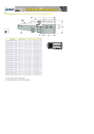
POSONIC
PS-EM16-192
8/16 Zone Expander Module
For PS-9192 Control Panel
INSTALLATION MANUAL
VERVION 1.1
INDEX
Chapter
Page
1. Introduction………............................................................................................................. 3
2. 6-Position Dip Switch Settings ......................................................................................... 3
3. Register the PS-EM16-192 Expander…........................................................................... 3
4. Wiring the PS-EM16-192.................................................................................................. 3
5. Terminal Description ........................................................................................................ 4
6. Wiring Diagram................................................................................................................. 4
7. Default Zone Configurations............................................................................................. 5
8. Programming Zone Configuration & Partition....................................................................7
9. Programming Worksheets………………………………………………………………………8
10. Specifications ...............................................................................................................13
-2-
1. INTRODUCTION
The PS-EM16-192 is a microprocessor-controlled 16-zone expander for PS-9192 control panel. Up to 23
pcs of PS-EM16-192 expanders can be added to the control panel with a maximum zone number of 192
zones. Each expander has an tamper switch and power isolator making it ideal for use in a remote
location.
2. 6-POSITION DIP SWITCH SETTINGS:
The first thing that must be decided is the starting zone of this particular zone expander. The starting zone
must be on a boundary of eight (8) zones. The sixteen (16) zones for this module will move out from this
starting position. There are stick-on zone labels to indicate the zone numbers that you select. To set the
starting zone, set the dip switch according to the table below:
NOTE: THE POSITION OF ALL SWITCHES IS ONLY UPDATED WHEN THE PS-EM16-192 IS
POWERED UP. BEFORE YOU CHANGE THE POSITION OF THESE SWITCHES YOU MUST
POWER DOWN THE EXPANDER.
Starting Zone
No.
9
9
17
25
33
41
49
57
65
73
81
89
97
105
113
121
129
137
145
153
161
169
177
185
Expander
No.
22
23
16
17
18
19
20
21
96
97
98
99
100
101
102
103
104
105
106
107
108
109
110
111
Dip Switch 1
Dip Switch 2
Dip Switch 3
Dip Switch 4
Dip Switch 5
OFF
OFF
ON
ON
OFF
OFF
ON
ON
OFF
OFF
ON
ON
OFF
OFF
ON
ON
OFF
OFF
ON
ON
OFF
OFF
ON
ON
OFF
OFF
OFF
OFF
ON
ON
ON
ON
OFF
OFF
OFF
OFF
ON
ON
ON
ON
OFF
OFF
OFF
OFF
ON
ON
ON
ON
OFF
OFF
OFF
OFF
OFF
OFF
OFF
OFF
ON
ON
ON
ON
ON
ON
ON
ON
OFF
OFF
OFF
OFF
OFF
OFF
OFF
OFF
OFF
OFF
OFF
OFF
OFF
OFF
OFF
OFF
OFF
OFF
OFF
OFF
OFF
OFF
OFF
OFF
ON
ON
ON
ON
ON
ON
ON
ON
OFF
ON
OFF
ON
OFF
ON
OFF
ON
OFF
ON
OFF
ON
OFF
ON
OFF
ON
OFF
ON
OFF
ON
OFF
ON
OFF
ON
Dip switch 6 - Dip switch 6 is used to disable the second block of eight (8) zones on this zone expander.
This can be done if only an eight- (8) zone expander is required in a particular expander address. To
disable the second group of eight (8) zones on this expander, turn dip switch 6 ON. In this case, up to 23
expanders can be added to the system creating a total of 192 zones.
3. REGISTER THE PS-EM16-192 EXPANDER
The PS-9192 panel has the ability to automatically find and store in its memory the presence of all
keypads, zone expanders, wireless receivers and any other module connected to the data terminal. This
allows these modules to be supervised by the control panel. To register the modules, enter the Program
Mode of PS-9192 control panel, and when the Program Mode is exited, it will automatically register the
devices. The register process takes about 12 seconds, during which time the Service LED will illuminate.
User codes will not be accepted during the register process. Once a module is registered, if it is not
detected by the control panel, the Service LED will illuminate.
-3-
4. WIRING THE PS-EM16-192
Wire the zones according to the wiring diagram on page 4. NOTE: Any unused zones must have the EOL
resistor across it (unless all eight are disabled by dip switch 6).
5. TERMINAL DESCRIPTION:
Terminal
POS
COM
DATA
TAMP
AUX
Z9
COM
Z10
Z11-Z24
Description
Connect to the KP POS terminal of the PS-9192 panel. Current draw is 30mA.
Connect to the KP COM terminal of the PS-9192 panel.
Connect to the KP DATA terminal of the PS-9192. (See the wiring diagram for wire
specifications.) Max cable length is 750m.
Connect as shown below. If not used, connect to a COM terminal.
This can be used to power devices directly from PS-EM16-192. Since power is coming from
PS-9192, the current draw of these devices must be added to the total current draw of the PSEM16-192. This output is current limited to 100mA.
Connect to any cable of zone 9 alarm input loop. Connect the other cable of the loop to COM
terminal. Open or short of the loop will cause alarm. (See the wiring diagram for examples)
Common (–) terminal for zone 9 & 10.
Connect to any cable of zone 10 alarm input loop. Connect the other cable of the loop to
COM terminal. Open or short will cause alarm. (See the wiring diagram for examples).
Connection is same as Z9 & Z10.
6. WIRING DIAGRAM
Pos, Com, and Data - Connect to PS-9192 panel or PS-483 module.
Tam - Connect to Com terminal through a normally closed tamper switch.
Aux - Current limited to 100mA (MUST BE ADDED TO AUX POWER OF PANEL)
Z9-Z24 - Connect as described in the Terminal Description.
-4-
Maximum Wire Run when connected to
PS-9192 panel
If AUX terminal is used:
75m – 24 AWG
150m – 20 AWG
300m – 18 AWG
450m – 16 AWG
750m – 14 AWG
Maximum Wire Run when connected to
PS-483 power module
If AUX terminal is used:
75m – 22 AWG
150m – 18 AWG
300m – 16 AWG
450m – 14 AWG
750m – 12 AWG
If AUX terminal is not used:
75m – 24 AWG
220m – 24 AWG
300m – 22 AWG
600m – 20 AWG
750m – 18 AWG
If AUX terminal is not used:
150m – 22 AWG
220m – 20 AWG
300m – 20 AWG
600m – 16 AWG
750m – 16 AWG
7. DEFAULT ZONE CONFIGURATIONS
Zones can be programmed to be one of 30 different zones configurations (zone types). Configurations #
17 through 20 can be used for wireless or hardwired zones using European double EOL configuration.
The default zone configurations are listed below. These zone configurations can be customized by
programming address 110-169.
DATA
1
2
3
4
5
6
7
8
9
DESCRIPTION OF DEFAULT CONFIGURATION
Day Zone-instant when system is armed trouble zone when system is disarmed.
24-Hour Audible-Creates an instant yelping siren alarm regardless of the armed state of the
control panel
ENTRY/EXIT DELAY 1 - A trip will start entry delay 1. The lack of a trip during exit delay will
enable the Automatic Bypass or Instant mode if so programmed.
FOLLOWER WITH AUTO-BYPASS DISABLED - This zone will be instant when the system is
armed and no entry or exit delays are being timed. It is delayed during entry and exit delay
times. This zone will not bypass in Stay Mode, nor automatically bypass even if enabled in
Segment 1 / Address 23.
INTERIOR FOLLOWER WITH AUTO- BYPASS ENABLED - This zone will be instant when
the system is armed and no entry or exit delay is being timed. It is delayed during entry and exit
delay times. This zone will bypass in Stay Mode, and automatically bypass if enabled in
Segment 1 of Address 23.
INSTANT - This zone creates an instant alarm whenever it is tripped and the Armed LED is on.
24-HOUR SILENT - Creates an instant silent alarm regardless of the armed state of the control
panel. It will not display on the keypad.
FIRE - This zone will illuminate the Fire LED and sound the temporal siren each time the zone
is shorted. It will also rapidly flash the Fire LED indicating a trouble if the zone is open.
ENTRY/EXIT DELAY 2 - A trip will start entry delay 2. The lack of a trip during exit delay will
enable the Automatic Bypass or Instant mode if so programmed.
-5-
10
11
12
13
14
15
16
17
18
19
20
21
22
23
24
25
26
27
28
24-HOUR SILENT SUPERVISED - Creates an instant silent alarm regardless of the armed
state of the control panel. It will display on the keypad.
KEYSWITCH ZONE - This zone type will arm and disarm the partition or partitions of the
control panel that resides in each time the zone is shorted. Key-switch arming will report as
user #99.
INTERIOR FOLLOWER WITH "CROSS ZONE" ENABLED - This zone will be Instant when
the system is armed and no entry or exit delay is being timed. It is delayed during entry and exit
delay times. If a "Cross Zone" is not being timed it will start a "Cross Zone" timer. If a "Cross
Zone" is being timed it will create an Instant alarm. This zone will bypass in Stay Mode and
automatically bypass when enabled in Segment 1 of Address 23.
INSTANT ENTRY GUARD - This zone creates an instant alarm whenever it is tripped and the
Stay LED is off. It will start an entry delay time 2 if it is tripped and the system is armed and the
Stay LED is on.
ENTRY/EXIT DELAY 1 WITH GROUP BYPASS ENABLED - A trip will start entry delay 1.
This zone will bypass when the "Group Bypass" command is entered at the keypad. The lack
of a trip during exit delay will enable the Automatic Bypass or Instant mode if so programmed.
INTERIOR FOLLOWER WITH GROUP BYPASS ENABLED - This zone will be instant when
the system is armed and no entry or exit delays are being timed. It is delayed during entry/exit
delay times. This zone will bypass when the "Group Bypass" command is entered at the
keypad. This zone will bypass in Stay Mode and automatically bypass even if enabled in
Segment 1 / Address 23.
INSTANT WITH GROUP BYPASS ENABLED - This zone creates an instant alarm whenever
it is tripped and the Armed LED is on. This zone will bypass when the "Group Bypass"
command is entered at the keypad.
ENTRY/EXIT DELAY 1 WITH TAMPER ENABLED - A trip will start entry delay 1. The lack of
a trip during exit delay will enable the Automatic Bypass or Instant mode if so programmed.
This configuration group can be used to enable tamper on a wireless transmitter.
INTERIOR FOLLOWER WITH TAMPER AND AUTO-BYPASS ENABLED - This zone will be
instant when the system is armed and no entry or exit delay is being timed. It is delayed during
entry and exit delay times. This zone will bypass in Stay Mode and automatically bypass if
enabled in Segment 1 / Address 23. This configuration group can be used to enable
tamper on a wireless transmitter.
INSTANT WITH TAMPER ENABLED - This zone creates an instant alarm whenever it is
tripped and the Armed LED is on. This configuration group can be used to enable tamper
on a wireless transmitter.
ENTRY/EXIT DELAY 2 WITH TAMPER ENABLED - A trip will start entry delay 2. The lack of
a trip during exit delay will enable the Automatic Bypass or Instant mode if so programmed.
This configuration group can be used to enable tamper on a wireless transmitter.
GAS DETECTION- Creates an instant alarm regardless of the armed state of the control panel.
It will display on the keypad and activate the keypad sounder.
LOW TEMP DETECTION- Creates an instant silent alarm regardless of the armed state of the
control panel. It will display on the keypad and activate the keypad sounder.
HIGH TEMP DETECTION- Creates an instant silent alarm regardless of the armed state of the
control panel. It will display on the keypad and activate the keypad sounder.
MANUAL FIRE - This zone will illuminate the Fire LED and sound the temporal siren each time
the zone is shorted. It will also rapidly flash the Fire LED indicating a trouble if the zone is
open.
CHIME ONLY - Creates no alarm regardless of the armed state of the control panel. It will
chime anytime it is faulted and will display on the keypad. Local only.
INTERIOR FOLLOWER DELAY 2 - This zone will be instant when the system is armed and no
entry or exit delay is being timed. It is delayed during entry and exit delay 2 times. This zone
will automatically bypass if enabled in Segment 1 of address 23.
INTERIOR FOLLOWER FORCE ARMABLE - This zone will be instant when the system is
armed and no entry or exit delay is being timed. It is delayed during entry and exit delay 1
times. This zone will automatically bypass if enabled in Segment 1 of address 23.
ENTRY/EXIT FORCE ARMABLE DELAY 2 - A trip will start entry delay 2. The lack of a trip
during exit delay will enable the Automatic Bypass or Instant mode if so programmed.
-6-
29
30
INTERIOR FOLLOWER WITH ACTIVITY SUPERVISION ENABLED - This zone will be instant
when the system is armed and no entry or exit delay is being timed. It is delayed during entry
and exit delay times. It will send a report if the zone activity time is reached without a change of
state.
Refer to Address 40 / Segment 11. This zone will automatically bypass if enabled in Segment 1
of
address 23.
ENTRY/EXIT WITH ACTIVITY SUPERVISION ENABLED- A trip will start entry delay 1. It will
send a report if the zone activity time is reached without a change of state. Refer to address 40
/ Segment 11. The lack of a trip during exit delay will enable the Automatic Bypass or Instant
mode if so programmed.
8. PROGRAMMING THE ZONE CONFIGURATION AND PARTITION FOR EACH ZONE
The programming for all zone information is performed in PS-9192 control panel. For instructions on
programming the PS-9192, as well as changing the characteristics of a configuration group, please refer
to the Installation Manual of PS-9192. The following programming information is taken from the Installation
Manual of PS-9192.
ADDRESS 25 CONFIGURATION GROUP ZONES 1-8
(8 segments, numerical data) Address 25 contains the Configuration Group (Zone type) for zones 1-9.
Segment 1 is for zone 1; Segment 8 is for zone 8. Default configurations are found in the table on page 5.
ADDRESS 26 PARTITION SELECT ZONES 1-8
(8 segments, feature selection data) Address 26 is used to select the partition(s) that zones 1-8 reside in.
A zone may reside in any combination of the 8 partitions. If a burglary zone resides in more than 1
partition, it will only be active when all partitions are armed. A zone that resides in more than 1
partition will be reported to its lowest partition. Address 28 has 8 segments. Segment 1 corresponds
to zone 1 and Segment 8 corresponds to zone 8.
Segments 1 - 8:
1 = Partition # 1 3 = Partition # 3 5 = Partition # 5 7 = Partition # 7
2 = Partition # 2 4 = Partition # 4 6 = Partition # 6 8 = Partition # 8
ADDRESS 27 – 36 and 170 - 205
These addresses contain the Configuration Group and Partition Select for Zones 9 – 192. Use the
instructions
associated with Address 25 and 26 to program the remaining addresses. Worksheets for these addresses
are
included for your convenience.
-7-
9. PROGRAMMING WORKSHEETS
ADD
DESCRIPTION
DEFAULT
25
ZONES 1 – 8 CONFIGURATION GROUP
26
ZONES 1 - 8 PARTITION SELECT
Segment
Zone
1
9
1
2
3
4
5
6
7
8
2
10
1
2
3
4
5
6
7
8
27
ZONES 9 - 16 CONFIGURATION GROUP
28
ZONES 9 - 16 PARTITION SELECT
29
1
2
9
10
1
1
2
2
3
3
4
4
5
5
6
6
7
7
8
8
ZONES 17 – 24 CONFIGURATION GROUP
30
ZONES 17 - 24 PARTITION SELECT
31
1
2
17
18
1
1
2
2
3
3
4
4
5
5
6
6
7
7
8
8
ZONES 25 – 32 CONFIGURATION GROUP
32
ZONES 25 – 32 PARTITION SELECT
Segment
Zone
Segment
Zone
Segment
Zone
1
25
1
2
3
4
5
6
7
8
2
26
1
2
3
4
5
6
7
8
DATA
6-6-6-6-6-6-6-6
3
11
1
2
3
4
5
6
7
8
4
12
1
2
3
4
5
6
7
8
5
13
1
2
3
4
5
6
7
8
6
14
1
2
3
4
5
6
7
8
7
15
1
2
3
4
5
6
7
8
8
16
1
2
3
4
5
6
7
8
3
11
1
2
3
4
5
6
7
8
4
5
12
13
1
1
2
2
3
3
4
4
5
5
6
6
7
7
8
8
6-6-6-6-6-6-6-6
6
14
1
2
3
4
5
6
7
8
7
15
1
2
3
4
5
6
7
8
8
16
1
2
3
4
5
6
7
8
3
19
1
2
3
4
5
6
7
8
4
5
20
21
1
1
2
2
3
3
4
4
5
5
6
6
7
7
8
8
6-6-6-6-6-6-6-6
6
22
1
2
3
4
5
6
7
8
7
23
1
2
3
4
5
6
7
8
8
24
1
2
3
4
5
6
7
8
6
30
1
2
3
4
5
6
7
8
7
31
1
2
3
4
5
6
7
8
8
32
1
2
3
4
5
6
7
8
6-6-6-6-6-6-6-6
3
27
1
2
3
4
5
6
7
8
-8-
4
28
1
2
3
4
5
6
7
8
5
29
1
2
3
4
5
6
7
8
ADD
DESCRIPTION
DEFAULT
33
ZONES 33 – 40 CONFIGURATION GROUP
6-6-6-6-6-6-6-6
34
ZONES 33 – 40 PARTITION SELECT
Segment
Zone
3
5
3
6
1
33
1
2
3
4
5
6
7
8
2
34
1
2
3
4
5
6
7
8
3
35
1
2
3
4
5
6
7
8
ZONES 41 – 48 CONFIGURATION GROUP
4
36
1
2
3
4
5
6
7
8
DATA
5
37
1
2
3
4
5
6
7
8
6
38
1
2
3
4
5
6
7
8
7
39
1
2
3
4
5
6
7
8
8
40
1
2
3
4
5
6
7
8
5
45
1
2
3
4
5
6
7
8
6
46
1
2
3
4
5
6
7
8
7
47
1
2
3
4
5
6
7
8
8
48
1
2
3
4
5
6
7
8
3
4
51
52
1
1
2
2
3
3
4
4
5
5
6
6
7
7
8
8
6-6-6-6-6-6-6-6
5
53
1
2
3
4
5
6
7
8
6
54
1
2
3
4
5
6
7
8
7
55
1
2
3
4
5
6
7
8
8
56
1
2
3
4
5
6
7
8
3
59
1
2
3
4
5
6
7
8
5
61
1
2
3
4
5
6
7
8
6
62
1
2
3
4
5
6
7
8
7
63
1
2
3
4
5
6
7
8
8
64
1
2
3
4
5
6
7
8
6-6-6-6-6-6-6-6
ZONES 41 - 48 PARTITION SELECT
Segment
Zone
1
41
1
2
3
4
5
6
7
8
2
42
1
2
3
4
5
6
7
8
170
ZONES 49 – 56 CONFIGURATION GROUP
171
ZONES 49 – 56 PARTITION SELECT
172
1
2
49
50
1
1
2
2
3
3
4
4
5
5
6
6
7
7
8
8
ZONES 57 – 64 CONFIGURATION GROUP
173
ZONES 57 - 64 PARTITION SELECT
3
43
1
2
3
4
5
6
7
8
6-6-6-6-6-6-6-6
Segment
Zone
Segment
Zone
1
57
1
2
3
4
5
6
7
8
4
44
1
2
3
4
5
6
7
8
2
58
1
2
3
4
5
6
7
8
-9-
4
60
1
2
3
4
5
6
7
8
ADD
DESCRIPTION
174
ZONES 65 – 72 CONFIGURATION GROUP
175
ZONES 65 – 72 PARTITION SELECT
Segment
Zone
1
65
1
2
3
4
5
6
7
8
2
66
1
2
3
4
5
6
7
8
ZONES 73 – 80 CONFIGURATION GROUP
177
ZONES 73 – 80 PARTITION SELECT
178
1
2
73
74
1
1
2
2
3
3
4
4
5
5
6
6
7
7
8
8
ZONES 81 – 88 CONFIGURATION GROUP
179
ZONES 81 - 88 PARTITION SELECT
180
1
2
81
82
1
1
2
2
3
3
4
4
5
5
6
6
7
7
8
8
ZONES 89 – 96 CONFIGURATION GROUP
181
ZONES 89 - 96 PARTITION SELECT
Segment
Zone
Segment
Zone
1
89
1
2
3
4
5
6
7
8
6-6-6-6-6-6-6-6
3
67
1
2
3
4
5
6
7
8
176
Segment
Zone
DATA
DEFAULT
2
90
1
2
3
4
5
6
7
8
5
69
1
2
3
4
5
6
7
8
6
70
1
2
3
4
5
6
7
8
7
71
1
2
3
4
5
6
7
8
8
72
1
2
3
4
5
6
7
8
6-6-6-6-6-6-6-6
3
75
1
2
3
4
5
6
7
8
4
5
76
77
1
1
2
2
3
3
4
4
5
5
6
6
7
7
8
8
6-6-6-6-6-6-6-6
6
78
1
2
3
4
5
6
7
8
7
79
1
2
3
4
5
6
7
8
8
80
1
2
3
4
5
6
7
8
3
83
1
2
3
4
5
6
7
8
4
5
84
85
1
1
2
2
3
3
4
4
5
5
6
6
7
7
8
8
6-6-6-6-6-6-6-6
6
86
1
2
3
4
5
6
7
8
7
87
1
2
3
4
5
6
7
8
8
88
1
2
3
4
5
6
7
8
6
94
1
2
3
4
5
6
7
8
7
95
1
2
3
4
5
6
7
8
8
96
1
2
3
4
5
6
7
8
3
91
1
2
3
4
5
6
7
8
- 10 -
4
68
1
2
3
4
5
6
7
8
4
92
1
2
3
4
5
6
7
8
5
93
1
2
3
4
5
6
7
8
ADD
DESCRIPTION
182
ZONES 97 – 104 CONFIGURATION GROUP
183
ZONES 97 – 104 PARTITION SELECT
Segment
Zone
1
97
1
2
3
4
5
6
7
8
2
98
1
2
3
4
5
6
7
8
ZONES 105 – 1112 CONFIGURATION GROUP
185
ZONES 105 - 112 PARTITION SELECT
186
1
2
105
106
1
1
2
2
3
3
4
4
5
5
6
6
7
7
8
8
ZONES 113 – 120 CONFIGURATION GROUP
187
ZONES 113 - 120 PARTITION SELECT
188
1
2
113
114
1
1
2
2
3
3
4
4
5
5
6
6
7
7
8
8
ZONES 121 – 128 CONFIGURATION GROUP
189
ZONES 121 - 128 PARTITION SELECT
Segment
Zone
Segment
Zone
1
121
1
2
3
4
5
6
7
8
6-6-6-6-6-6-6-6
3
99
1
2
3
4
5
6
7
8
184
Segment
Zone
DATA
DEFAULT
2
122
1
2
3
4
5
6
7
8
- 11 -
4
100
1
2
3
4
5
6
7
8
5
101
1
2
3
4
5
6
7
8
6
102
1
2
3
4
5
6
7
8
7
103
1
2
3
4
5
6
7
8
8
104
1
2
3
4
5
6
7
8
6
110
1
2
3
4
5
6
7
8
7
111
1
2
3
4
5
6
7
8
8
112
1
2
3
4
5
6
7
8
6
118
1
2
3
4
5
6
7
8
7
119
1
2
3
4
5
6
7
8
8
120
1
2
3
4
5
6
7
8
6
126
1
2
3
4
5
6
7
8
7
127
1
2
3
4
5
6
7
8
8
128
1
2
3
4
5
6
7
8
6-6-6-6-6-6-6-6
3
4
5
107
108
109
1
1
1
2
2
2
3
3
3
4
4
4
5
5
5
6
6
6
7
7
7
8
8
8
6-6-6-6-6-6-6-6
3
115
1
2
3
4
5
6
7
8
3
123
1
2
3
4
5
6
7
8
4
5
116
117
1
1
2
2
3
3
4
4
5
5
6
6
7
7
8
8
6-6-6-6-6-6-6-6
4
124
1
2
3
4
5
6
7
8
5
125
1
2
3
4
5
6
7
8
ADD
DESCRIPTION
DEFAULT
190
ZONES 129 – 136 CONFIGURATION GROUP
6-6-6-6-6-6-6-6
191
ZONES 129 - 136 PARTITION SELECT
Segment
Zone
192
193
1
129
1
2
3
4
5
6
7
8
2
130
1
2
3
4
5
6
7
8
3
131
1
2
3
4
5
6
7
8
ZONES 137 – 144 CONFIGURATION
GROUP
ZONES 137 – 144 PARTITION SELECT
Segment
Zone
1
137
2
138
1
2
3
4
5
6
7
8
1
2
3
4
5
6
7
8
3
13
6
134
1
2
3
4
5
6
7
8
7
135
1
2
3
4
5
6
7
8
8
136
1
2
3
4
5
6
7
8
ZONES 145 – 152 CONFIGURATION GROUP
195
ZONES 145 - 152 PARTITION SELECT
196
1
2
145
146
1
1
2
2
3
3
4
4
5
5
6
6
7
7
8
8
ZONES 153 – 160 CONFIGURATION GROUP
197
ZONES 153 - 160 PARTITION SELECT
Segment
Zone
2
154
1
2
3
4
5
6
7
8
- 12 -
4
14
5
141
6
142
7
143
8
144
0
1
2
3
4
5
6
7
8
194
1
153
1
2
3
4
5
6
7
8
5
133
1
2
3
4
5
6
7
8
6-6-6-6-6-6-6-6
9
Segment
Zone
4
132
1
2
3
4
5
6
7
8
DATA
1
2
3
4
5
6
7
8
1
2
3
4
5
6
7
8
1
2
3
4
5
6
7
8
1
2
3
4
5
6
7
8
1
2
3
4
5
6
7
8
6
150
1
2
3
4
5
6
7
8
7
151
1
2
3
4
5
6
7
8
8
152
1
2
3
4
5
6
7
8
6
158
1
2
3
4
5
6
7
8
7
159
1
2
3
4
5
6
7
8
8
160
1
2
3
4
5
6
7
8
6-6-6-6-6-6-6-6
3
4
5
147
148
149
1
1
1
2
2
2
3
3
3
4
4
4
5
5
5
6
6
6
7
7
7
8
8
8
6-6-6-6-6-6-6-6
3
155
1
2
3
4
5
6
7
8
4
156
1
2
3
4
5
6
7
8
5
157
1
2
3
4
5
6
7
8
ADD
DESCRIPTION
DEFAULT
198
ZONES 161 – 168 CONFIGURATION GROUP
6-6-6-6-6-6-6-6
199
ZONES 161 – 168 PARTITION SELECT
Segment
Zone
1
161
1
2
3
4
5
6
7
8
2
162
1
2
3
4
5
6
7
8
3
163
1
2
3
4
5
6
7
8
200
ZONES 169 – 176 CONFIGURATION GROUP
201
ZONES 169 - 176 PARTITION SELECT
203
1
2
169
170
1
1
2
2
3
3
4
4
5
5
6
6
7
7
8
8
ZONES 177 – 184 CONFIGURATION
GROUP
ZONES 177 - 184 PARTITION SELECT
Segment
Zone
1
177
1
2
3
4
5
6
7
8
3
4
5
171
172
173
1
1
1
2
2
2
3
3
3
4
4
4
5
5
5
6
6
6
7
7
7
8
8
8
6-6-6-6-6-6-6-6
2
178
1
2
3
4
5
6
7
8
3
179
1
2
3
4
5
6
7
8
204
ZONES 185 – 192 CONFIGURATION GROUP
205
ZONES 185 - 192 PARTITION SELECT
Segment
Zone
1
185
1
2
3
4
5
6
7
8
5
165
1
2
3
4
5
6
7
8
6
166
1
2
3
4
5
6
7
8
7
167
1
2
3
4
5
6
7
8
8
168
1
2
3
4
5
6
7
8
6
174
1
2
3
4
5
6
7
8
7
175
1
2
3
4
5
6
7
8
8
176
1
2
3
4
5
6
7
8
6-6-6-6-6-6-6-6
Segment
Zone
202
4
164
1
2
3
4
5
6
7
8
DATA
2
186
1
2
3
4
5
6
7
8
- 13 -
4
180
1
2
3
4
5
6
7
8
5
181
1
2
3
4
5
6
7
8
6
182
1
2
3
4
5
6
7
8
7
183
1
2
3
4
5
6
7
8
8
184
1
2
3
4
5
6
7
8
6
190
1
2
3
4
5
6
7
8
7
191
1
2
3
4
5
6
7
8
8
192
1
2
3
4
5
6
7
8
6-6-6-6-6-6-6-6
3
187
1
2
3
4
5
6
7
8
4
188
1
2
3
4
5
6
7
8
5
189
1
2
3
4
5
6
7
8
9. SPECIFICATIONS
Input Power
AUX Power Output
12VDC Supplied from PS-9192 or PS-483
Power supply to other devices, max. 100mA
Current Consumption
Loop Resistance
30mA
300 ohms Maximum
Loop Reponse
Operating Temperature
Selectable 50mS or 500mS
0 to 50 degrees C
Dimensions
Weight
152 x 56mm
67 g
- 14 -