1
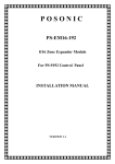
INSTALLATION MANUAL
Table of Contents
Page
General Description ........................................................................2
4-Position Dip Switch Settings.........................................................2
Enrolling the NX-216 Expander .......................................................2
Wiring the NX-216...........................................................................2
Terminal Description .......................................................................4
Wiring Diagram ...............................................................................4
Default Zone Configurations ............................................................5
Programming Zone Configuration & Partition............................. 5 - 6
Specifications and Warranty............................................................8
CADDX CONTROLS, INC.
1420 NORTH MAIN STREET
GLADEWATER, TEXAS 75647
TOLL FREE 800-727-2339
FAX 903-845-6811
GENERAL DESCRIPTION
The NX-216 is a microprocessor-controlled 16-zone expander for the NX-8 control panel. Up to five NX-216
expanders can be added to the NetworX control panel with a maximum zone count of 48 zones. Each expander
has an optional tamper switch and power isolator making it ideal for use in a remote location.
4-POSITION DIP SWITCH SETTINGS
The first thing that must be decided is the starting zone of this particular zone expander. The starting zone must
be on a boundary of eight (8) zones. The sixteen (16) zones for this module will move out from this starting
position. There are stick-on zone labels to indicate the zone numbers that you select. To set the starting zone, set
the dip switch according to the table below:
NOTE: THE POSITION OF ALL SWITCHES IS ONLY UPDATED WHEN THE NX-216 IS POWERED UP.
BEFORE YOU CHANGE THE POSITION OF THESE SWITCHES YOU MUST POWER DOWN THE EXPANDER.
Starting Zone Number
Dip Switch 1
Dip Switch 2
Dip Switch 3
9
ON
OFF
OFF
17
OFF
ON
OFF
25
ON
ON
OFF
33
OFF
OFF
ON
41
ON
OFF
ON
Dip switch 4 - Dip switch 4 is used to disable the second block of eight (8) zones on this zone expander. This
can be done if only an eight- (8) zone expander is required in a particular expander location. In this case, up to
5 expanders can be added to the system creating a total of 48 zones. To disable the second group of eight (8)
zones on this expander, turn dip switch 4 on.
ENROLLING THE NX-216 EXPANDER
The NX-8 has the ability to automatically find and store in its memory the presence of all keypads, zone expanders,
wireless receivers, and any other device on the keypad buss. This allows these devices to be supervised by the
control panel and illuminate the "Service" LED if one is not detected. To enroll the devices, enter the program
mode of the NX-8 control panel, using the procedure outlined in the Installation Manual, and enter [9]-[1]-[5]-[#].
When the Program Mode is exited, the NX-8 will automatically enroll the device. Enrolling takes about 12
seconds, during which time the “Service” LED will illuminate. User codes will not be accepted during the enrolling
process. If a speaker is attached to the NX-8, it will click at this time. If a siren or bell is attached to the NX-8, it
will sound for about 1 second. Once a module is enrolled, the “Service” LED will illuminate if it is not detected by
the control panel.
WIRING THE NX-216
Wire the zones according to the wiring diagram on page 3. NOTE: Any unused zones must have the EOL
resistor across it (unless all eight are disabled by dip switch 4).
2
NX-216 ZONE EXPANDER
TERMINAL DESCRIPTION
TERMINAL
DESCRIPTION
POS
Connect to the KP POS terminal of the NX-8. Current draw is 30 mA.
COM
Connect to the KP COM terminal of the NX-8.
DATA
Connect to the KP DATA terminal of the NX-8. (See the wiring diagram for wire specifications.)
TAM
Connect as shown below. IF NOT USED, CONNECT TO A COM TERMINAL.
AUX
Can be used to power devices directly from the NX-216. Power is coming from the NX-8,
therefore the current draw of these devices must be added to the total current draw of the NX216. This output is current limited to 100 mA.
Z9
Connect to one side of zone 9 loop. Connect the other side to COM terminal. Open or short
causes alarm. (See the wiring diagram for examples)
COM
Common (-) terminal for zones 9 & 10.
Z10
Connect to one side of zone 10 loop. Connect the other side to COM terminal. Open or short
causes alarm. (See the wiring diagram for examples).
Z11-Z24
Connect as described for Z9 & Z10.
WIRING DIAGRAM
3
NX-216 ZONE EXPANDER
DEFAULT ZONE CONFIGURATIONS
Zones can be programmed to be one of twenty different zone configurations (zone types). Configurations # 17
through 20 can be used for wireless or hardwired zones using European double EOL configuration. The default
zone configurations are listed below. These zone configurations can be customized by programming locations
110-149.
DATA
DESCRIPTION OF DEFAULT CONFIGURATION
“1”
DAY ZONE - Instant when system is armed trouble zone when system is disarmed.
“2”
24-HOUR AUDIBLE - Creates an instant yelping siren alarm regardless of the armed state of the control panel.
ENTRY/EXIT DELAY 1 - A trip will start entry delay 1. The lack of a trip during exit delay will enable the
“3”
Automatic Bypass or Instant mode if so programmed.
INTERIOR FOLLOWER WITH AUTO-BYPASS DISABLED - This zone will be instant when the system is armed
“4”
and no entry or exit delays are being timed. It is delayed during entry and exit delay times. This zone will not
bypass in Stay Mode, nor automatically bypass even if enabled in Segment 1 / Location 23.
INTERIOR FOLLOWER WITH AUTO- BYPASS ENABLED - This zone will be instant when the system is armed
“5”
and no entry or exit delay is being timed. It is delayed during entry and exit delay times. This zone will bypass in
Stay Mode, and automatically bypass if enabled in Segment 1 of Location 23.
“6”
INSTANT - This zone creates an instant alarm whenever it is tripped and the Armed LED is on.
24-HOUR SILENT - Creates an instant silent alarm regardless of the armed state of the control panel. It will not
“7”
display on the keypad.
FIRE - This zone will illuminate the Fire LED and sound the steady siren each time the zone is shorted. It will also
“8”
rapidly flash the Fire LED indicating a trouble if the zone is open.
ENTRY/EXIT DELAY 2 - A trip will start entry delay 2. The lack of a trip during exit delay will enable the
“9”
Automatic Bypass or Instant mode if so programmed.
24-HOUR SILENT SUPERVISED - Creates an instant silent alarm regardless of the armed state of the control
“10”
panel. It will display on the keypad.
KEYSWITCH ZONE - This zone type will arm and disarm the partition or partitions of the control panel that
“11”
resides in each time the zone is shorted. Keyswitch arming will report as user #99.
INTERIOR FOLLOWER WITH "CROSS ZONE" ENABLED - This zone will be Instant when the system is armed
and no entry or exit delay is being timed. It is delayed during entry and exit delay times. If a "Cross Zone" is not
“12”
being timed it will start a "Cross Zone" timer. If a "Cross Zone" is being timed it will create an Instant alarm. This
zone will bypass in Stay Mode and automatically bypass when enabled in Segment 1 / Location 23.
INSTANT ENTRY GUARD - This zone creates an instant alarm whenever it is tripped and the Stay LED is off.
“13”
It will start an entry delay time 1 if it is tripped and the system is armed and the Stay LED is on.
ENTRY/EXIT DELAY 1 WITH GROUP BYPASS ENABLED - A trip will start entry delay 1. This zone will bypass
“14” when the "Group Bypass" command is entered at the keypad. The lack of a trip during exit delay will enable the
Automatic Bypass or Instant mode if so programmed.
INTERIOR FOLLOWER WITH GROUP BYPASS ENABLED - This zone will be instant when the system is
armed and no entry or exit delays are being timed. It is delayed during entry/exit delay times. This zone will
"15
bypass when the "Group Bypass" command is entered at the keypad. This zone will bypass in Stay Mode and
automatically bypass even if enabled in Segment 1 / Location 23.
INSTANT WITH GROUP BYPASS ENABLED - This zone creates an instant alarm whenever it is tripped and
"16"
the Armed LED is on. This zone will bypass when the "Group Bypass" command is entered at the keypad.
ENTRY/EXIT DELAY 1 WITH TAMPER ENABLED - A trip will start entry delay 1. The lack of a trip during exit
"17" delay will enable the Automatic Bypass or Instant mode if so programmed. This configuration group can be
used to enable tamper on a wireless transmitter.
INTERIOR FOLLOWER WITH TAMPER AND AUTO-BYPASS ENABLED - This zone will be instant when the
system is armed and no entry or exit delay is being timed. It is delayed during entry and exit delay times. This
"18"
zone will bypass in Stay Mode and automatically bypass if enabled in Segment 1 / Location 23. This
configuration group can be used to enable tamper on a wireless transmitter.
INSTANT WITH TAMPER ENABLED - This zone creates an instant alarm whenever it is tripped and the Armed
"19"
LED is on. This configuration group can be used to enable tamper on a wireless transmitter.
ENTRY/EXIT DELAY 2 WITH TAMPER ENABLED - A trip will start entry delay 2. The lack of a trip during exit
"20" delay will enable the Automatic Bypass or Instant mode if so programmed. This configuration group can be
used to enable tamper on a wireless transmitter.
4
NX-216 ZONE EXPANDER
PROGRAMMING THE ZONE CONFIGURATION AND PARTITION FOR EACH ZONE
The programming for all zone information is performed in the NX-8 control panel. For instructions on accessing
and programming the NX-8, as well as changing the characteristics of a configuration group, refer to the NX-8
Installation Manual. The following programming information is taken from the NX-8 Installation Manual.
LOCATION 27 CONFIGURATION GROUP ZONES 9-16 (8 segments, numerical data)
Location 27 contains the Configuration Group (Zone type) for zones 9 -16. Segment 1 is for zone 9; Segment 8
is for zone 16. Default configurations are found in the table on page 4.
LOCATION 28 PARTITION SELECT ZONES 9-16 (8 segments, feature selection data)
Location 28 is used to select the partition(s) that zones 9-16 reside in. A zone may reside in any combination of
the 8 partitions. If a burglary zone resides in more than 1 partition, it will only be active when all partitions
are armed. A zone that resides in more than 1 partition will be reported to its lowest partition. Location
28 has 8 segments. Segment 1 corresponds to zone 9 and Segment 8 corresponds to zone 16.
Segments 1 - 8:
1 = Partition #1
2 = Partition #2
3 = Partition #3
4 = Partition #4
5 = Partition #5
6 = Partition #6
7 = Partition #7
8 = Partition #8
LOCATION 29 CONFIGURATION GROUP ZONES 17-24 (8 segments, numerical data)
Location 29 contains the Configuration Group (Zone type) for zones 17-24. Segment 1 is for zone 17; Segment
8 is for zone 24. Default configurations are found in the table on page 4.
LOCATION 30 PARTITION SELECT ZONES 17-24 (8 segments, feature selection data)
Location 30 is used to select the partition(s) that zones 17-24 reside in. A zone may reside in any combination of
the 8 partitions. If a burglary zone resides in more than 1 partition, it will only be active when all partitions
are armed. A zone that resides in more than 1 partition will be reported to its lowest partition. Location
30 has 8 segments. Segment 1 corresponds to zone 17 and Segment 8 corresponds to zone 24.
Segments 1 - 8:
1 = Partition #1
2 = Partition #2
3 = Partition #3
4 = Partition #4
5 = Partition #5
6 = Partition #6
7 = Partition #7
8 = Partition #8
LOCATION 31 CONFIGURATION GROUP ZONES 25-32 (8 segments, numerical data)
Location 31 contains the Configuration Group (Zone type) for zones 25-32. Segment 1 is for zone 25; Segment
8 is for zone 32. Default configurations are found in the table on page 4.
5
NX-216 ZONE EXPANDER
LOCATION 32 PARTITION SELECT ZONES 25-32 (8 segments, feature selection data)
Location 32 is used to select the partition(s) that zones 25-32 reside in. A zone may reside in any combination of
the 8 partitions. If a burglary zone resides in more than 1 partition it will only be active when all partitions
are armed. A zone that resides in more than 1 partition will be reported to its lowest partition. Segment 1
corresponds to zone 25 and Segment 8 corresponds to zone 32.
Segments 1 - 8:
1 = Partition #1
2 = Partition #2
3 = Partition #3
4 = Partition #4
5 = Partition #5
6 = Partition #6
7 = Partition #7
8 = Partition #8
LOCATION 33 CONFIGURATION GROUP ZONES 33-40
(8 segments, numerical data)
Location 33 contains the Configuration Group (Zone type) for zones 33-40. Segment 1 is for zone 33; Segment
8 is for zone 40. Default configurations are found in the table on page 4.
LOCATION 34 PARTITION SELECT ZONES 33-40 (8 segments of feature selection data)
Location 34 is used to select the partition(s) that zones 33-40 reside in. A zone may reside in any combination of
the 8 partitions. If a burglary zone resides in more than 1 partition, it will only be active when all partitions
are armed. A zone that resides in more than 1 partition will be reported to its lowest partition. Segment 1
corresponds to zone 33 and Segment 8 corresponds to zone 40.
Segments 1 - 8:
1 = Partition #1
2 = Partition #2
3 = Partition #3
4 = Partition #4
5 = Partition #5
6 = Partition #6
7 = Partition #7
8 = Partition #8
LOCATION 35 CONFIGURATION GROUP ZONES 41-48
(8 segments of numerical data)
Location 35 contains the Configuration Group (Zone type) for zones 41-48. Segment 1 is for zone 41; Segment
8 is for zone 48. Default configurations are found in the table on page 4.
LOCATION 36 PARTITION SELECT ZONES 41-48 (8 segments, feature selection data)
Location 36 is used to select the partition or partitions that zones 41-48 reside in. A zone may reside in any
combination of the 8 partitions. If a burglary zone resides in more than 1 partition it will only be active when
all partitions are armed. A zone that resides in more than 1 partition will be reported to its lowest partition.
Location 36 has 8 segments. Segment 1 corresponds to zone 41 and Segment 8 corresponds to zone 48.
Segments 1 - 8:
1 = Partition #1
2 = Partition #2
3 = Partition #3
4 = Partition #4
5 = Partition #5
6 = Partition #6
7 = Partition #7
8 = Partition #8
6
NX-216 ZONE EXPANDER
SYSTEM NOTES
SPECIFICATIONS
OPERATING POWER
12VDC Supplied from NX-8 or NX-320
AUXILIARY POWER
Supplied from NX-8 or NX-320
Current limited to 100mA
CURRENT DRAW
30mA
LOOP RESISTANCE
300 Ohms Maximum
LOOP RESPONSE
Selectable 50mS or 500mS
OPERATING TEMPERATURE
32 to 120 degrees F
DIMENSIONS
6.0" Wide
2.125" High
1.0" Deep
SHIPPING WEIGHT
2 lbs.
FIVE YEAR LIMITED WARRANTY
CADDX CONTROLS, INC. GUARANTEES THIS PRODUCT AGAINST DEFECTIVE PARTS
AND WORKMANSHIP FOR TWENTY-FOUR (24) MONTHS FROM DATE OF MANUFACTURING.
IF ANY DEFECT APPEARS DURING THE WARRANTY PERIOD, RETURN IT TO CADDX
POSTAGE PREPAID. THE UNIT WILL BE REPAIRED AND RETURNED AT NO CHARGE.
FOR THE REMAINING 36 MONTHS OF WARRANTY, THE CHARGE TO REPAIR OR REPLACE THIS
MODULE WILL NOT EXCEED $10.00 PLUS SHIPPING AND HANDLING.
CADDX ASSUMES NO LIABILITY FOR CONSEQUENTIAL OR INDIRECT DAMAGE AND
ACCEPTS NO RESPONSIBILITY FOR REPAIRING DAMAGE TO THE PRODUCT CAUSED BY
MISUSE, CARELESS HANDLING, OR WHERE REPAIRS HAVE BEEN MADE BY OTHERS.
NO OTHER GUARANTEE, WRITTEN OR VERBAL, IS AUTHORIZED BY OR
ON BEHALF OF CADDX CONTROLS, INC., GLADEWATER, TEXAS.
CADDX CONTROLS, INC.
1420 NORTH MAIN STREET
GLADEWATER, TEXAS 75647
TOLL FREE 800-727-2339
FAX 903-845-6811
NX-216 INSTALLATION MANUAL
NX216IE98
REV. E (07-20-98)