1
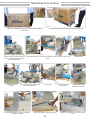
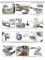
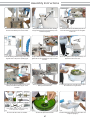
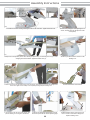
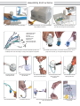
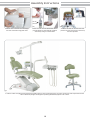
Installation Manual - Quality
Index
Installation Enviroment
03
Before Starting
04
Tools
04
Assembly Instructions
05
Final Instructions
11
02
Installation Enviroment
Dear technician,
This manual has been developed to guiding as proper installation for Quality dental unit,
aiming to standardize the process of installation, making it easier and ensure customer
satisfaction.
Before installing the equipment, when possible, please check the installation
environment, place where the equipment will be installed, available spaces, placement of
furniture, patient’s movement area, work position of the professional(s ) and assistant(s), to
ensure the best placement and performance of the equipment, granting a comfortable
working environment not only for professionals but also for patients.
Make sure the necessary supplies are available for the proper functioning of the
equipment:
Compressed Air: The dental compressor must be oil free with dynamic pressure between
5.5 and 7.0 bar (80-100 psi), minimum displacement of 150 l / min and 30 liters reservoir. Please
recommend the use of coalescing filter in the equipment’s air inlet.
Plumbing: - Up to 10 meters: use hose Ø1/4". From 10 to 20 meters: use hose Ø5/16". Use
specific woven hose for compressed air. For longer stretches, it is recommended project of
distribution with specific rigid pipe.
Water to Spittoon Bowl and Cup-filler: Install an easy access block valve to stop water
supply to the equipment at the end of working day and also to limit water pressure, if
necessary. The water pressure must to be between 2.8 and 6.0 BAR and ideal pH between 6.5
and 8. If the water pressure is not enough, we recommend consulting an experienced
professional for hydraulic systems. We also recommend to use a filter in the equipment’s
water inlet.
Sewage System: The sewage pipe must have good hydraulic declivity and should
preferably be installed underground. Use Ø40 mm pipe.
Power Supply: Single phase installation, proper grounding and provided with an exclusive
circuit breaker. If the electricity network has tension variations, we do recommend power
stabilizer.
Vacuum Pump Sewage System: Connecting Junction Box to the Vacuum pump
installation, use curved pipes. Don’t use 90º fittings, to avoid debris deposits and decreasing
suction power.
Fixing chair to the ground: For safety reasons, both for the professional and patient, we
recommend to fix the equipment on the ground, with anchor bolt screws provided with the
equipment.
Fixation is strong recommended to prevent shifting of the equipment and consequently
disruption of electrical, hydraulic and pneumatic connections. Damages caused to the
equipment for not fixing the same are entire responsibility of the technician and the owner.
03
Before Starting
Before starting the equipment installation, please check the following items:
1- Installation site: Check the doors’ width to ensure the equipment’s box will get in; otherwise
you must to unpack the equipment before.
2- Power supply: Check if electrical power is available at dental office. Check also voltage and
where circuit breaker’s box is located.
3- Compressed Air: Make sure the compressor is installed and working properly. Check
plumbing conditions. If necessary proceed drainage / cleaning to avoid water and debris into
the equipment. Check filters conditions. If there is no filter, ask the customer to install it.
Check the main compressed air block valve. If there is no block valve, install it inside the
Junction Box.
4- Water Network: Check water supply and its pressure. If water pressure is not enough we do
recommend to install water pressurizer system. Make sure there is water block valve
available. If there is no water block valve, install it inside the Junction Box.
5- Hydro-sanitary, electrical and compressed air sketches: Check the exactly location of each
abovementioned plumbing to avoid accidents when using the drilling machine.
6- Chair fixation point: Inform the customer about necessity of chair anchorage. Position the
chair according the dental office layout.
Tools
Necessary tools to intall the equipment:
Universal Plier with
electrical insulation
Cutting Plier with
electrical insulation
Snap Rings
Plier
Flat Blade Screwdriver: 3/16 x 4”
Philips Screwdriver:
3/16 x 4"
Blunt Scissors
L Wrench:
11 x 11mm
2 Combination
Wrenchs:13mm
Magnetic Level
Hex Wrench
3mm and 5mm
Adjustable Wrench
Hammer Drill
Concret drill 12mm
Extension Cord 10m
Cleaning Cloth
04
Assembly Instructions
P01
P02
1- Place the box next to the installation site. Use the existent handles for
transportation.
P03
2-Cut the three green tapes with cutting pliers. Pull up housing cover.
P04.2
P04.1
P04.3
P05
5-Chair Backrest
3-Remove the protective plastic with blunt 4-Stool Upholstery (P04.1) and Stool Structure (P04.3), which is tied on the opposite side
scissors and carefully removing from the
(P04.2);
chair the following items:
F07
P06
6-Chair armrests and
headrest;
P08
P07
7-Arm of Operation Light, which is tied at
the three indicated points.
P11
11-Remove the front plastic cover of the pantograph
using philips screwdriver.
P09
8-Junction Box;
P10
9-Water tank and Chair
Anchorage Kit.
10-Move up the working
table from the chair seat.
P13
P12
12-Remove the finishing covers and keep them.
05
13-Remove the chair fixing screws using L Wrench
11mm.
Assembly Instructions
P14
P15
14-Remove the chair from wooden base. .
P16
15-Release the seat fixing handle screw.
P17
P18
17-Release the handle screw and remove the seat
lower covering.
18-Release the four screws for the rear pantograph
cover using flat screwdriver.
16-Remove the seat upholstery, watching the screw
to avoid damages (detail).
P19
230V
220V
19-Remove the rear pantograph cover and keep the
four screws.
Cristal cable
for voltage
selection
127V
118V
(Factory Standard: 220V)
P20.2
P20.1
20-Before plug in the equipment, please check the network voltage and proceed necessary changes at transformer and fuse. Plug in the equipment (P20.1) and turn
it on. Firstly releasing the emergency button (P20.2) and after by pressing the On/Off Switch (detail).
P21
21-Raise the seat up to its maximum height.
P22
22-Release the counter nuts above indicated using two 13mm wrenches. Thread up the top nut (touching the metal
plate). Remove the lower nut from the screw and keep it.
06
Assembly Instructions
P23
23-Unscrew the holder nuts using 13mm wrench
and remove the Delivery Unit from the holder.
P24
P25
24-Couple the Delivery Unit to the chair, watching
the right insertion of the screws and Delivery Unit’s
metal bracket (detail).
25-Take the two nuts from the holder (P23) and use
it to fix the Delivery Unit to the chair. Do not tighten
screws now.
2º
1º
2º
1º
P26
P27
26-Put the Working Table at working position and fix
magnetic level on the post of Operating Light.
P28
27-Adjust Delivery Unit level parallel to the chair and
tighten the nuts as indicated above using two 13mm
wrenches.
P31
P29
P30
29-Adjust the right level and tighten the nuts on the
delivery unit metal bracket using two 13mm
wrenches.
30-Plug in electrical connectors and place on the
Delivery Unit metal bracket.
Spittoon Bowl
Strainer
28-Turn the magnetic level to adjust the delivery unit
perpendicular level to the chair.
31-Unpack the water unit, unroll the hoses and place
the instruments on its right holders.
Water ½" x
1/4" Connector
1x
1x
Venturi Saliva Ejector Set
2x
Ejector Tip
Ø 9,5mm
1x
Water and
Air Clamp
2x
Sewer Clamp
5x
Air inlet
Connector
1x
The availability of items will change according
to the equipment’s configuration.
P32
32-Check if all above items are available.
P33
P34
33-Install the Spittoon Bowl Strainer.
07
34-Place handpieces tubings in the right holders and
couple the syringe tip.
Assembly Instructions
1
P35
2
P36
35-Install the seat lower covering watching the holder on the chair frame. Tighten the handle screw.
36-Fix the rear pantograph cover tightening the four
screws, watching sizes and right places to insert
them (detail).
2
1
3
P37
P38
37Replace the seat upholstery on the chair, watching the specific fit (1) and watching the screw (2) to avoid
damaging the chair’s PC Board. Tighten the handle screw (3).
38-Raise up the backrest frame and remove the
finishing cover.
P40
P39
39-Remove the screws from the backrest using a 5mm Hex Wrench, place backrest on its frame and handtighten the
center screw. Tighten screws carefully to avoid upholstery damages.Replace finishing cover.
P41
41-Fix armrests on the chair using 13mm wrench, and
place the finishing covers using 3mm Hex Wrench.
P42
40-Place the headrest on the backrest.
P43
42-Plug in the Operating Light electrical connector
and move it up into the arm. Fix the Operating Light.
08
43-After install the anchors on the ground, use
11mm L wrench to fix the chair to the ground.
Replace finishing covers.
Assembly Instructions
P45
P44
44-Remove carefully all remaining packaging.
1
45-Remove the front plactic cover of the pantograph
using a philips screwdriver.
46-Place Junction Box over all connections and
pass the hoses through the connector (detail).
1-Saliva Ejector Drain
2-Saliva Ejector Air
3-Air Inlet
4-Cup-Filler Drain
5-Cuspidor Drain
6-Water Inlet
7-Vacuum Pump Drain
8-Vacuum Pump Wires
3
2
P46
4
5
6
7
2
1
3*
8
P47
*Opcional item.
P48
47-Identify each hose and connections. All hoses are identified by labels. The
availability of the hoses will change according to the equipment configuration.
P49
P50
49-Conect the hose
fromcuspidor drain.
50-Conect the hose from
cup-filler drain.
48-Install the Sewer Connector (1), the water connector (2) and vacuum
pump drain connector. (3). Use proper sealing tape or similar.
P51
P52
51-Conect the hose from air
to the venturi saliva ejector.
52-Conect the venturi saliva
ejector set to Sewer
Connector.
P53
53-Conect the hose from
Saliva Ejector drain.
N P G
P54
54-Install water inlet hose.
P55
55-Install air inlet hose.
P56.1
P56.2
56-Conect the vacuum pump drain hose and wires.
This is an optional item.
09
P57
57-Install the electrical wires
as indicated.
Assembly Instructions
Note the
water limit
P58
58-Check all the connections to avoid leakages,
then close Junction Box using plastic rivets.
P59
P60
59-Fill in the water tank with filtered water, remove
protection plastic from water tank filter. Install the
water tank by turning it counterclockwise.
60-Fit the stool seat over stool structure. Seat
yourself on the stool and check the e check its up
and down adjustment.
F61
61-Check if all items of equipment have been properly installed, make sure all are functioning properly, such as the controls of the chair and pneumatic devices.
Remove all leftover packages remaining before presenting the installed equipment to the customer.
10
Final Instructions
After finishing the installation, check operation of all instruments, chair movements’
switches and Operating Light. Double check all air/water connections to ensure there is no
leakage.
After checking all the equipment operations, instruct the user about its correct managing.
Check all handpieces to be used in the equipment and pressure compatibility. If necessary
make duly adjustments.
Show to the customer each main valve (air inlet, water for spittoon bowl and cup-filler).
Also explain about zero and working positions, how to record working positions as well as
correct managing of Operating Light.
Explain about the water replacement, using filtered drinking water, the correct way to
install and remove water tank, as well as its water level.
Fill in the warranty form with the customer, guiding him on each item. Give him the
owner's manual and instruct about its reading.
General Instructions:
Able Professional Operation: This equipment must be operated by professional who have
the ability to work on dental procedures.
Storage: Before the first operation or after long stop periods (weekends, holidays,
vacations), the user must eliminate all air and water stuck inside the hoses, shut off the watercocks, depressurize and empty the water tank, turn the general switch and the general circuit
breaker off. For reactivation of the unit, verify the functioning of the entire set before starting
operation.
Direct exposure to Sunlight: The equipment must not be exposed directly to solar light to
prevent from the plastic covers and/or the upholstery to wear out precociously.
Environmental awareness: The organic residues, the contaminated materials and
disposable items must be properly eliminated according to the rules of the local law.
Daily Cares:
- Replace the bottle water;
- Clean the unit as per instructions on the Owner’s Manual for Quality Equipment;
- Shut the water and compressed air valves and turn the circuit breaker off after work;
- Check the compressor before start using the dental set;
- Drain the humidity filter of the compressor before starting using the dental set.
‘Equipment properly installed + well oriented user = well satisfied customer!’
11
OLSEN INDÚSTRIA E COMÉRCIO S.A.
Av. Ivo Lucchi, 68 - Distrito Industrial - Palhoça - Santa Catarina - Brasil - Caixa Postal - 59 - CEP 88133-510
Fone/Fax: +55 48 2106-6000 - www.olsen.odo.br
OLSEN SHOW ROOM PREMIER - Filial Olsen
Rua República do Iraque, 1369 - Campo Belo - CEP 04611-002 - Fone/Fax: +55 11 3539-3944
16
5402102 Rev. 00
Certificação FDA 10042326