1
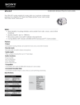
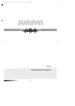
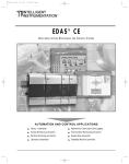
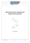
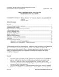
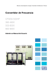
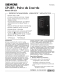
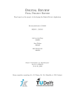
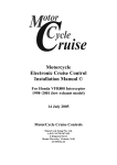
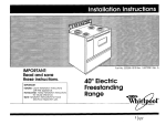
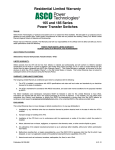
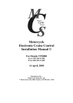
Cerberus Division
CERBERUS PYROTRONICS™
MODEL PB-1191
Linear Smoke Detection System
Operation and Installation Manual
Siemens Building Technologies, Inc.
8 Fernwood Road
Florham Park, New Jersey 07932
P/N 315-095424-3
Siemens Building Technologies, Ltd.
50 East Pearce Street
Richmond Hill, Ontario L4B 1B7 CN
PB-1191 Beam Detector
Overview
Figure 1
PBA-1191
Characteristics
•
•
•
•
•
•
•
•
•
•
•
•
•
Microprocessor-controlled signal processing
Suitable for surveillance ranges from 17 to 280 feet
Operates according to the principle of light-attenuation by smoke
Response behavior selectable In 3 sensitivity stages
Automatic digital compensation of ambient Influences
High immunity to extraneous light
Transmitter and receiver installed in the same housing
Easy installation, adjustment, and commissioning
Two-wire installation
Comprehensive accessories
New diagnostic capabilities with fuzzy logic
Efficient signal processing algorithms with application-specific characteristics
Comprehensive EMC concept based on the latest technologies enables the detector to be
installed in difficult environments
• Integrated multi-coincidence circuit suppresses extreme electrical and optical noise signals
• Automatic and comprehensive self-test design
1
PB-1191 Beam Detector
Design
The PB-1191 linear smoke detector has the following components:
• Base PBB-1191 consisting of:
– Terminal support with terminals
The base housing features six PG16 tapped cable inlets.
• Detector module PBA-1191 consisting of:
– Transmitter
– Receiver
– Lens
– Electronics
Insert the plug-in detector module just prior to alignment and commissioning. Align the Iens to the
reflector by setting the adjustment on the PBL-1191.
Reflectors
Different reflectors are available for different distances:
– 17ft to 99ft
– 99ft to 164ft
– 164ft to 214ft
– 214ft to 262ft
– 66ft to 280ft
Reflector foil PBR-1193 (I0 x 10cm) 1 pc.
Reflector foil PBR-1192 (20 x 20cm) 1 pc.
Reflector foil PBR-1192 (20 x 20cm) 4 pcs.
Reflector foil PBR-1192 (20 x 20cm) 9 pcs.
Prism made of glass PBR-1191 (cat's eye) 1 pc.
Short distance filter
For shorter distances between 17ft and 33ft, use an additional short distance filter as listed below:
– 17ft to 26ft
– 23ft to 33ft
PBF-1191B
PBF-1191A
Accessories:
• Detector heater PBH-1191 protects against condensation of the lens
Auxiliary tools:
• Detector adjustment set PBL-1191 consisting of:
– Adjustment device
– Test filter
– Target device
2
PB-1191 Beam Detector
Operating principle
The transmitter (IRLED) emits an invisible infrared (IR) pulse through the transmitter lens. The IR
pulse crosses over the measuring section and reaches the reflector located opposite the detector. The
reflector deflects the IR pulse back to the point of origin. The receiver lens directs the reflected IR
pulse to a silicon photodiode. The resulting electrical signal is evaluated by the electronics.
Receiver
Coverage Area
Transmitter
Reflector
PBR-1191
Detector
PBA-1191
Figure 2
Linear smoke detector without smoke
If smoke penetrates the measuring section, part of the light beam is absorbed by the smoke particles
while another part is scattered by the smoke particles; that is, the light beams merely change direction.
The remaining light reaches the reflector. The remaining light is then reflected and once again passes
through the measuring section and is further attenuated. Thus only a small portion of the beam
reaches the receiver and the signal (S smoke) becomes smaller.
Scattering
Scattering
Light Beam
Absorption
Smoke
Particles
Scattering
Figure 3
Measuring principle of the linear smoke detector with smoke
Attenuation = Absorption + Scattering
3
PB-1191 Beam Detector
Technical Data
Parameters
Operating voltage
Symbol
Unit
Value
min.
Ub
V
18
typ.
max.
Conditions
28
(quiescent)
Umax
V
30
Switch-on current
Ie
mA
2.8
Operating current
(quiescent condition)
Ib
mA
Alarm voltage at I A = 1 ... 10mA
UA
V
5
11
Maximum permissible voltage
1.5
2.8
Alarm current at U b = 24V
IA
mA
40
75
Reset voltage
UR
V
2
6
Reset time (U R = 2V)
tR
s
Distance between detector and
L
FT
2
17
280
reflector
Response sensitivity
reduced
standard
increased
D1
Compensation (if beam is
attenuated)
%
%
%
%
Compensation speed
%/h
Self-test interval
min.
Response indicator
Voltage
Current
Uie
Iie
Electromagnetic compatibility
Operating temperature
Ta
V
mA
50
4
15
3
V/m
50
C
-25
O
Humidity <30OC
>30OC
6
60
1MHx...1GHz
+60
<95% rel
<29g/m3
Storage temperature
Tl
Detector heater (optional)
Supply voltage
Operating current
UH
IH
(maximum 1 detector per detection line)
4
Attenuation of the beam
(See TABLE on page 22.)
65
50
30
C
-30
+75
VDC
mA
20
33
30
50
O
Transient condensation
allowed
Regulated DC
PB-1191 Beam Detector
Design and Principle of Operation
Detector
Short Distance Filter
Sighting Device
(mirror with backsight)
Sighting device (foresight)
Receiver Lens
Locking Screw
Knurled Screw For
Horizontal Adjustment
Knurled Screw For
Vertical Adjustment
Locking Screw
Transmitter Lens
Program Switch
Detector Heater Terminal
Reed Contact (initialization)
Connector for
Adjustment Device
Response Indicator
Figure 4
The Detector
Structure of the infrared beam
The infrared beam emitted by the transmitter to the reflector is not a strictly parallel bundle of rays.
It exhibits a certain degree of scattering which makes it conical in shape. The radiation energy decreases as you move towards the outside edges of the beam and can be divided into the three regions:
• effective
• core
• scattered
The reflector retransmits the received light.
5
PB-1191 Beam Detector Manual
Effective
region
Core
region
Scattered
region
Detector
PBA-1191
Reflector
PBR-1191
Figure 5
Structure of the infrared beam
• The effective region corresponds to the ribbon connecting transmitter, reflector and receiver.
• The core region contains sufficient radiation energy to operate the system.
• The energy in the scattered region is not sufficient to ensure reliable operation of the system.
Reflector
PBR-1191
5 ft.
Detector
PBA-1191
280 ft.
Figure 6
Diameter of the core region
Alignment Possibilitites
The infrared beam can be adjusted by 10° increments horizontally and in 5° increments vertically from
the center axis. When selecting the optimum mounting location, remember that this adjustment range
can be fully used. Experience has shown that the detector and reflector should be arranged as parallel
as possible especially with distances of >162.5 feet, as this makes adjustment simpler.
Detector
PBA-1191
10°
Reflector
PBR-1191
44 ft.
10°
44 ft.
280 ft.
Figure 7
Horizontal adjustment range of the optical system - max. 10° each side of the axis
6
PB-1191 Beam Detector Manual
Reflector
PBR-1191
Detector
PBA-1191
22 ft.
5°
5°
22 ft.
280 ft.
Figure 8
Vertical adjustment range of the optical system - max. 5° above and below the axis
Note: One rotation of the knurled screw moves the beam at 280 ft. approximately 3 ¾ ft.
Reflectors
Retroreflectors reflect the received light beam in parallel to the latter. For this reason the retroreflector
does not have to be installed parallel to the detector. Also vibrations and distortions of the reflector
mounting wall do not cause any problems. Another advantage is that any extraneous light is also
reflected in its own direction and consequently does not reach the receiver.
Reflector
Reflector
max. + 20°
max. + 20°
Reflector
Figure 9
The reflector can be mounted inclined a maximum of ± 20O in all directions
PBR-1191 prism
The retroreflecting prism has the shape of a pyramid whose lateral faces are formed by isosceles
orthogonal triangles. Light beams entering through the base are completely reflected twice on the
lateral faces and reflected back through the base.
The prism is installed in a housing that is identical to the one used for the detector base. The reflector
is equipped with a reflector heater. If condensation is possible, connect the heater to a 24V supply.
7
PB-1191 Beam Detector Manual
Light beam
Figure 10
PBR-1191 reflector and reflection principle
PBR-1192, PBR-1193 reflector
This reflector consists of microprismatic elements that are formed by transparent, synthetic resin
sealed to a plastic substrate.
Compatibility
COMPATIBLE EQUIPMENT
System
8
Zone
Module
System - 3
ZB-35
MXL
CZM-4
MXL-IQ
CZM-4
PXL
PCM-1
PZE-4B
SXL-EX
SZE-4X
PB-1191 Beam Detector Manual
Planning
Fundamentals of planning
The linear smoke detector PBA-1191 is ideal for certain applications. Use it to supplement or replace
point-type smoke detectors. Refer to the Fields of Use table for suitable applications.
FIELDS OF USE
Very Suitable:
Suitable:
Large and high halls
Aircraft hangars
Cable and energy ducts
Churches
Buildings with artwork ceilings of historical interest
Rooms with complex ceiling sructures
Rooms with strong air currents
Heavy soiling of point detectors (textile and wood processing)
Monitoring at different levels
Expensive installation and maintenance of point detectors,
for example:
-- in sawtooth roofs
-- very high rooms
-- where point detectors would have to be
suspended at a lower level
Underground garages >9ft high (min)
Computer rooms
Under floor
Above ceiling
Corridors
Inner courtyards (malls)
Open-plan offices
Cross zone releasing appliances
In combination with flame detectors
Operating conditions
The distance between the PBA-1191 and the reflector must be between 17 ft and 280 ft.
- There must be a permanent line of vision between the PBA-1191 and the reflector. Care should
be taken to ensure that the IR beam is not interrupted by moving objects such as overhead
cranes, etc., which can lead to trouble signals.
- If point detectors cannot be used because of the interfering effects of smoke, steam, or dust,
note that the PBA-1191 will only solve the problem in certain cases.
- Avoid frontal incidence of sunlight, light from halogen lamps, etc. on the PBA-1191.
- Always mount the PBA-1191 in the vicinity of the ceiling (See Figure 11 for distances). The
detector placement must not be too close to or too far from the ceiling.
- The PBA-1191 is also suitable for very high rooms. As a supplementary measure, install
additional PBA-1191s at different levels and/or use additional flame detectors.
9
PB-1191 Beam Detector Manual
Monitoring areas with flat ceilings
Min. spacing between two
parallel beams determined by
distance PBA-1191 and reflector
(See Figure 20)
Distance between PBA-1191
and reflector 17 - 280 ft.
Max. distance from ceiling
1 ft. for rooms <33 ft. high
(See Figures 21 & 22)
Max. width of monitored area
determined by height of room
(See Figure 23)
min 1 ft.
Figure 11
Detector layout in areas with flat ceilings
Monitoring areas with sloping ceilings
To be defined as sloping, a ceiling must have an angle of inclination of at least 11 O which corresponds
to >7.0 inch/yard. With gable roofs which have a slope of >0.5, always arrange a monitoring beam in
the gable area.
Additional PBA-1191s on the slope of the ceiling
The number of PBA-1191s required results from the maximum permissible monitoring width shown in
Figure 23.
1/4
10
1/4
1/4
1/4
Figure 12
Arrangement with 3 monitoring beams on a sloping ceiling
PB-1191 Beam Detector Manual
1/3
1/6
1/6
1/3
Figure 13
If the ceiling slopes only slightly (N <0.5), the monitoring beam in the gable is unnecessary
Both distances are determined by height of the room
(See Figure 23.)
Height of room
When the sides of the roof are unequal,
the unit must be displaced from the
center towards the less steep side.
Figure 14
Positioning underneath unequal sloping ceilings
With sloping ceilings the smoke is channeled into the gable, resulting in an increased smoke concentration in this area. Therefore, the monitoring width for each PBA-1191 can be increased according to
Figure 23.
11
PB-1191 Beam Detector Manual
Monitoring areas with beam constructions
Note that the term beams, also covers such structures as air conditioning ducts which are mounted up
to 0.5 ft below the ceiling.
Layout underneath beam construction
If the beam construction is less than 20% of the total height of the room, the units of the linear smoke
detector can be mounted below the beams as indicated in Figure 15.
min. 1 ft.
a
100%
<20%
Note: When calculating the width of the monitored area, only the distance up to the
beam construction counts as the height of the room.
a: Height for determining max. width of
monitored area
Figure 15
Detector layout underneath beam construction
Layout within the beam area
When the beam construction is more than 20% of the total height of the room, then the beams can be
considered as room dividers and each section must be individually monitored.
100%
<20%
Note: When distance exceeds maximum monitored area, mount more than one linear
smoke detector per section.
Figure 16
Detector layout within beam construction
12
PB-1191 Beam Detector Manual
Detection of smoldering fire in high rooms
10 ft. up to
60% of the
room height
PBA-1191
Reflectors
In order to detect smoldering fires with weak thermal current even in high rooms, the second IR beam
must be arranged at the assumed height of the spread of smoke of a smoldering fire.
Figure 17
Detection of smoldering fires in high rooms with two linear smoke detectors
Guideline for distances between PBA-1191 and reflector
Distance PB reflector
17 — 33 ft
33 — 99 ft
99 — 164 ft
164 — 214 ft
214 — 262 ft
66 — 280 ft
Types and number of reflectors
Short distance filter +
1 PBR-1193
1 PBR-1193
1 PBR-1192
4 PBR-1192
9 PBR-1192
1 PBR-1191
If a number of reflectors are used, they must be arranged close together and in the form of a square.
Distances are approximate; they depend on detector and reflector tolerances and can easily vary by a
few yards. The important thing is that sufficient signal strength is achieved.
Penetration of panes of glass
With the reflector principle, the penetration of panes of glass is subject to certain restrictions.
• Panes of glass must be absolutely smooth, clear and firmly installed.
• Panes of glass must never be positioned at an angle to the optical axis, in which the pane of
glass has the effect of a mirror and can reflect the beam back to the receiver (angle of incidence = angle of reflection).
• No more than 2 panes of 3/16 inch glass may be penetrated.
• Each pane of glass reduces the distance by 66 feet.
13
PB-1191 Beam Detector Manual
PBA-1191
Pane of glass
Partial light
scatter
Partial light
scatter
PBR-1191
PBA-1191
Pane of glass
PBR-1191
min. 10°
CORRECT - THE RECEIVER IS NOT AFFECTED
INCORRECT - THE RECEIVER IS AFFECTED
Figure 18
With the penetration of panes of glass, check the angle in relation to the optical axis
Glass wall
Partial light
scatter
Partial light
scatter
PBA-1191
PBR-1191
correctly
positioned
PBR-1191
incorrectly
positioned
PLAN
PBA-1191
PBR-1191
Glass wall
FRONT ELEVATION
PBR-1191
correctly
positioned
PBR-1191
incorrectly
positioned
PBA-1191
Glass wall
Figure 19
Application example for the penetration of pages of glass
14
PB-1191 Beam Detector Manual
Minimum distances between two pairs of detectors
The monitoring beam must not be mounted closer than 1 ft. to the ceiling, walls, installations, and
stored material.
In order to prevent the mutual interference of two or more PBA-1191 detectors where there is an
increasing distance between PBA-1191 and reflector, maintain an ever-increasing transverse distance
between PBA-1191 and reflector.
Figure 20
Minimum distance between two parallel IR beams
Beam spacing from the ceiling
In order for the IR beam to detect the smoke, it is normally mounted immediately beneath the cushion
of warm air. The higher the room, the further away the PBA-1191 and the reflector should be mounted
from the ceiling.
Figure 21
Distance from IR beam ⇒ flat ceiling (N < 0,2)
15
PB-1191 Beam Detector Manual
NOTE: The steeper the gable roof, the greater the distance must be between the IR beam in
the gable and the ridge.
Figure 22
Distance from IR beam ⇒ sloping ceiling (N > 0,2)
Maximum monitoring width
The monitoring width can be increased with increasing room height.
Figure 23
Monitoring width dependent on the room height
If the monitoring beam is set at a low level in order to detect a smouldering fire, use the distance
between the floor and detector instead of the room height. However, choose a narrower monitoring
width to cover increased risks.
16
PB-1191 Beam Detector Manual
Measures against condensation
If the PBA-1191 or the reflector is mounted on cool outside walls or in rooms in which there is high
humidity and a rapid increase in temperature (e.g. sunshine on a non-insulated roof), use the detector
heating unit PBH-1191. If condensation on the front cover causes troubles or false alarms, or for short
distances, use the reflector PBR-1191 with built-in heating.
Installation locations
When installation locations are rigid and vibration-free, large temperature fluctuations (e.g., between
day and night) have only a slight influence on steel girders and do not greatly affect the building structure. However, if the installation location is not rigid, the closely bundled infrared beam can drift from
the receiver and cause an alarm or trouble signal. Unstable installation locations include:
•
•
•
the walls of rooms constructed of steel which expand and contract due to the
temperature coefficient of steel
masonry walls upon which a steel roof has been constructed
non-bonded wooden beam construction
In the cases listed above the PBA-1191 must be mounted on the rigid structural element, while the
reflector can be mounted on the unstable wall.
PBR-1191
PBA-1191
INCORRECT
Figure 24
Deflection of the IR beam caused by heat on the steel roof
PBA-1191
PBR-1191
CORRECT
Figure 25
Possible solution: mounting the PB-1191 on the stable surface
and mounting the reflector on the unstable wall
17
PB-1191 Beam Detector Manual
Accessibility
The PB-1191 must always be easily accessible in high halls for commissioning and servicing. Suitable
equipment for this purpose includes fixed ladders, catwalks, etc. or safe mobile equipment such as
stacker trucks, sky-workers etc.
Figure 26
Difficult and dangerous work using a ladder
Figure 27
Precise and safe work using a permanent plafform
18
PB-1191 Beam Detector Manual
Installation
Mounting
6"
5 3\8"
Surface mounting directly on the wall (minimum clearance to ceiling and other obstacles at least 1 ft)
3/16"
5 3/8"
Base PBB-1191
4 5\8"
3/16"
PG16
Detector module
PBA-1191
Mounting plane
PBB-1191
NOTE: The response
indicator should always
be at the bottom.
Figure 28
Installation of the PBA-1191
6"
5 3\8"
Detector module
PBA-1191
3/16"
Reflector heater
5 3/8"
1¾"
2 5\8"
PG16
Mounting plane
PBR-1191
Figure 29
Installation of the PBR-1191 Reflector
19
PB-1191 Beam Detector Manual
Wiring
The detector is installed with a twisted 2-wire line from base to base.
The PBB-1191 base contains one terminal block with 6 terminals for connecting the detector to the
line and for connecting the external response indicator. The terminal block incorporates a slide switch
jumper which places the end of line device in the circuit for initial continuity check. When the detector
is first installed, this jumper is automatically disengaged and remains that way.
Caution: Slide switch must be intact and engaged or trouble conitions will not be annunciated.
The opposite terminal block is supplied for the detector heater.
Short distance filter
Short
distance
filter
Figure 30
Insert short distance filter for distances < 33 feet
Detector heater
In the event of danger of condensation, the installation of the detector heater is recommended
NOTE: Supply voltage 24V is necessary.
The opposite terminal block is supplied together with the detector heater and is used for connecting
the detector heater.
20
PB-1191 Beam Detector Manual
Detector heater
connection
Connection
adjustment unit
Figure 31
Connection of the dector heater
Connection
RLI-1 or RLI-2
End of line
device
To UL Listed Siemens
Building Technologies, Inc.
Control Panel
Response
Indicator
MB = RED pulse signal (for adjusting the
lenses during detector production)
Z = auxillary terminal
Auxillary supply for
detector heater
(optional)
24V
NOTE: Only one detector may be connected per zone circuit.
Figure 32
Connection diagram
21
PB-1191 Beam Detector Manual
Commissioning
Settings
• Remove the detector cover.
• Set the DIP switches.
The detector has 3 sensitivity settings - REDUCED, STANDARD, and INCREASED.
Set the response threshold with DIPswitch S1 and S2.
The transmitter intensity (strong, weak) is set with DIPswitch S3.
The S3 DIPswitch, which governs the transmitter intensity is set to STRONG by default. If the signal
amplitude is too high (display on the adjustment unit: Range = 13, signal > 50), the transmitter can be
set to WEAK. If the measurement section is < 33 ft., a supplementary filter must be installed.
Function
S1
Reduced Sensitivity (65%)
(See TABLE below.)
off
S2
S3
S4
S5
S6
on
Standard Sensitivity (50%)
(See TABLE below.)
on
Increased Sensitivity (30%)
(See TABLE below.)
on
on
off
on
Weak Transmitter Signal
Strong Transmitter Signal
off
on
Conventional
Reserved
S6 OFF
Fault at beam interruption
(<30s or >60s)
Beam Distance
off
Allowable Sensitivity Setting
17 ft. to 33 ft.
Increased only
33 ft. to 98 ft.
Standard only
98 ft. to 164 ft.
Standard and Reduced
164 ft. to 280 ft.
Reduced only
Figure 33
Settings
22
PB-1191 Beam Detector Manual
Preliminary adjustment
•
Install the alignment device on the detector. The mirror and the front sight must be
installed without play!
•
Unfasten the locking screw.
•
Align the detector lens to the reflector. The detector lens can be adjusted with the
knurled screws. Check by using the mirror and front sight - the target center and
the apex of the sight must be within the circle.
•
Apply zone power.
•
Connect the adjustment unit to the detector. Note: Install a new battery. Switch
the adjustment unit to ON and AUTO-RANGE. The correct range is measured
automatically.
When the mechanical adjustment is correct, a signal >2 shows on the adjustment
unit. This signal changes in large increments when the knurled screw is turned.
•
Remove the aiming device.
Mirror with
backsight
Eye
Foresight
Locking screw
Knurled screw for
horizontal
adjustment
Locking screw
Reflector
Knurled screw for
vertical adjustment
Figure 34
Mounting the aiming device and aligning the detector to the reflector
23
PB-1191 Beam Detector Manual
Final Adjustment
•
Set the switch on the adjustment unit to AUTO-RANGE.
•
Using the knurled screws, fine-adjust the detector lens to display the maximum level
in the RANGE display.
Note: The knurled screws should be turned slowly in order to avoid large signal
jumps.
•
When the maximum value is obtained, (it must be between min. 4 and max. 13) set
the switch to FIX-RANGE. The range level is now programmed into the detector to
set the internal amplifiers.
•
Adjust the knurled screws to display the maximum level in the SIGNAL display.
Caution: If the signal value can be adjusted to >60, the range level was not adjusted to its maximum. Switch back to AUTO-RANGE and readjust to the maximum
range level. Then repeat the signal level adjustment.
The RANGE and SIGNAL levels on the adjustment unit should both be set to the
maximum.
•
Engage the locking screws.
•
Switch the adjustment unit to FIX-RANGE.
Connection
adjustment unit
Figure 35
Front plate of the adjustment unit
•
Cover the reflector.
Completely cover the reflector with a dark cover. The signal should decrease to <2.
If this is not the case, the detector has not been aligned to the reflector but to a
reflecting obstacle in the environment of the measurement section. Repeat the
adjustment procedure.
24
•
Disconnect the adjustment unit from the detector.
•
Reinstall the detector cover.
PB-1191 Beam Detector Manual
Initialization
To initialize the detector, activate a reed relay located near the internal response indicator with the
supplied magnet. A flashing response indicator signals initialization.
Reed relay rear of the
response indicator
Magnet
Figure 36
Initialization with the magnet
During the initialization, the working range of the electronics (RANGE), the compensation value, all
smoothing algorithms and diagnostics, and the staus are set to an initial value. All required thresholds
are calculated. At the same time a self-test is performed.
•
lnitialization with the magnet.
Place the magnet directly behind the response indicator to activate the Reed relay
(Black or red point = magnet).
As soon as the response indicator flashes, the compensation value is formed (approximately 30 sec.). Do not interfere with the measurement during this time.
When the initialization is completed, the response indicator turns off. If any procedural error has been made, a new initialization can be started at any time with the
magnet.
•
Test alarm with test filter.
Place the test filter immediately in front of the detector and cover the entire
measurement window. When an alarm is triggered, the response indicator turns on
after approximately 10 seconds.
•
The commissioning is now completed.
25
PB-1191 Beam Detector Manual
Troubles / Overhaul
Trouble
Removing the detector triggers a trouble condition (zone line interruption). Blocking the IR Beam also
triggers a trouble condition (in approximately 1 minute).
Reflection
If a reflective surface comes too close to the coverage area or near the detector, a reflection can
occur.
As a result, the measured value increases significantly above the compensation value and remains at
that level. The system reports a trouble to the control unit.
Functional check/ overhaul
The detector self-test automatically subjects the PBA-1191 to an extensive electronic functional check.
Nevertheless it is necessary to physically check the functions on site at regular intervals by triggering
the detector with a suitable test filter (usually once per year). Detectors that do not respond or which
are mechanically damaged must be replaced.
All detector covers and reflectors should be cleaned regularly with a soft piece of cloth which is either
dry or soaked with a mild soap solution, depending on the environmental conditions and severity of
contamination at the installation site. Do not use any solvents or pressurized liquids.
26
Siemens Building Technologies, Inc.
8 Fernwood Road
Florham Park, New Jersey 07932
P/N 315-095424-3
Siemens Building Technologies, Ltd.
50 East Pearce Street
Richmond Hill, Ontario L4B 1B7 CN