1
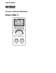
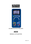
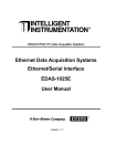
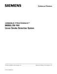
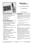
25005_source 6/14/02 7:28 AM Page 1
EDAS CE
®
OPEN ARCHITECTURE MONITORING
AND
CONTROL SYSTEMS
AUTOMATION AND CONTROL APPLICATIONS
▲
Factory Automation
▲
Networked or Stand-alone Data Logging
▲
Process Monitoring and Control
▲
Environmental Monitoring and Control
▲
Machine Monitoring and Control
▲
Remote Data Acquisition
▲
Laboratory Automation
▲
Embedded Machine Controllers
25005_source 6/14/02 7:28 AM Page 2
TABLE OF CONTENTS
EDASCE – O
PEN
ARCHITECTURE MONITORINGAND CONTROL SYSTEMS
Overview . . . . . . . . . . . . . . . . . . . . . . . . . . . . . . . . . . . . . . . . . . . . . . . . . . . . . . . . . . . . . . . . . .2
Description . . . . . . . . . . . . . . . . . . . . . . . . . . . . . . . . . . . . . . . . . . . . . . . . . . . . . . . . . . . . . . . .3
Software and Development Tools . . . . . . . . . . . . . . . . . . . . . . . . . . . . . . . . . . . . . . . . . . . . . . . . . .4
EDASCE Module Specifications:
Base Units . . . . . . . . . . . . . . . . . . . . . . . . . . . . . . . . . . . . . . . . . . . . . . . . . . . . . . . . . . . . . . .5
Power Module . . . . . . . . . . . . . . . . . . . . . . . . . . . . . . . . . . . . . . . . . . . . . . . . . . . . . . . . . . . . .6
Digital I/O Module . . . . . . . . . . . . . . . . . . . . . . . . . . . . . . . . . . . . . . . . . . . . . . . . . . . . . . . . . .7
Analog Input Module . . . . . . . . . . . . . . . . . . . . . . . . . . . . . . . . . . . . . . . . . . . . . . . . . . . . . . . . .8
Digital Input Modules . . . . . . . . . . . . . . . . . . . . . . . . . . . . . . . . . . . . . . . . . . . . . . . . . . . . . . . .9
Digital Output Module . . . . . . . . . . . . . . . . . . . . . . . . . . . . . . . . . . . . . . . . . . . . . . . . . . . . . . . 10
Analog Output Module . . . . . . . . . . . . . . . . . . . . . . . . . . . . . . . . . . . . . . . . . . . . . . . . . . . . . . 11
Serial Port Module . . . . . . . . . . . . . . . . . . . . . . . . . . . . . . . . . . . . . . . . . . . . . . . . . . . . . . . . . 12
Relay Output Module . . . . . . . . . . . . . . . . . . . . . . . . . . . . . . . . . . . . . . . . . . . . . . . . . . . . . . . 13
Digital Output (TRIAC) Module . . . . . . . . . . . . . . . . . . . . . . . . . . . . . . . . . . . . . . . . . . . . . . . . . 14
Ordering Information . . . . . . . . . . . . . . . . . . . . . . . . . . . . . . . . . . . . . . . . . . . . . . . . . . . . . . . . . 15
Contact Information . . . . . . . . . . . . . . . . . . . . . . . . . . . . . . . . . . . . . . . . . . . . . . . . . . . .Back Cover
EDAS CE
www.edasce.com
▲
Intelligent Instrumentation
1
25005_source 6/14/02 7:28 AM Page 3
EDAS CE 2000 SERIES
OVERVIEW
CLIENTS
MACHINES
CLIENTS
EDAS CE
EDAS-2000E SERIES
OPEN ARCHITECTURE MONITORING
AND CONTROL SYSTEMS
SENSORS
ETHERNET
RS-232 DEVICES
KEY FEATURES/BENEFITS
▲
Modular I/O
Industrial modular case design provides 8 to 192
channels of isolated I/O per base unit. Supports any
combination of analog and digital I/O, and RS-232
data, giving EDAS CE the flexibility to create a wide
range of automation and control applications.
▲
▲
Open Architecture
Leverage open standards for lower total cost of
ownership. Open systems environment provides easy
interface to existing and future plant-wide systems.
Take advantage of existing network infrastructure,
lower cost network components and trained staff for
networking and application development.
▲
Ethernet delivers high-speed networking with 10 and
100 Mb/s. Most facilities already have Ethernet
installed and components are widely available at very
low cost. Ethernet and TCP/IP are standard, integrated
components of the PC, Windows, and the Internet.
▲
▲
Non-Volatile Storage
EDAS CE can support up to 500 MB of non-volatile
storage allowing it to be used in stand-alone data
logging applications or to continue operating and
logging data in the event of a network disruption.
www.edasce.com
▲
Intelligent Instrumentation
Network Standards
EDAS CE supports TCP/IP, UDP, SNMP, DHCP, HTTP and
time synchronization.
Windows CE
Easy application development using Microsoft’s
eMbedded Visual C++. Windows CE 3.0 provides true
multitasking, allowing both control and monitoring
functions to run simultaneously on an EDAS CE
system.
Ethernet Connectivity
2
25005_source 6/14/02 7:28 AM Page 4
EDAS CE 2000 SERIES
DESCRIPTION
Open Architecture Industrial I/O
The EDAS® CE is designed using open architecture
standards allowing for easy development and
deployment into exiting and future automation systems.
By leveraging the efficiencies of standard technology,
you are ensuring a lower total cost of ownership. With
EDAS CE, you can take advantage of your existing
network infrastructure, lower cost components and
trained staff for networking and application
development. Digital I/O, analog I/O, RS-232,
10/100BaseT Ethernet, and Windows CE, all in an
industrial modular package, make EDAS CE the ideal
solution for a wide range of applications in today’s open
architecture manufacturing environment.
Modular I/O Offers Flexibility
The modular architecture of EDAS CE allows you to
mix and match I/O as necessary to meet the needs of a
wide range of automation, control, and measurement
applications. Each EDAS CE system supports up to 12
modules allowing for systems from 8 to 192 I/O points
per base unit.
The modules provide connectivity to virtually all
sensors including temperature, pressure, flow, voltage,
current, contact closures and RS-232 devices. All in a
rugged and reliable industrial DIN-rail mount package.
Networked and Stand-Alone Operation
With built-in 10/100BaseT Ethernet the EDAS CE is
ready to run networked applications, providing
connectivity across your enterprise. Other networked
devices can communicate with the EDAS CE to read
and write its I/O points or an application can be
downloaded to run directly on the unit. Applications
running on the EDAS CE can operate stand-alone
allowing the unit to provide real-time control during
network downtime. The EDAS CE supports Compact
Now Available with Entivity Studio
EDAS CE is now available with the Entivity Studio™
runtime. Applications developed with Studio can now
be targeted for the EDAS CE as an embedded
application.
Entivity Studio offers a complete automation and
control software solution with transparent control
scalability across a full range of Microsoft Windows
platforms, built-in productivity analysis, enterprise
connectivity, and a Unified Development Environment
incorporating Microsoft® Visio® drawing technology
for control logic and human-machine interface (HMI).
Microsoft eMbedded Development Tools
With EDAS CE, applications can be developed using
Microsoft’s eMbedded™ Visual Tools. These tools
allow users to write, download and debug applications
for the EDAS CE using the popular eMbedded Visual
C++ programming environment. The built-in
networking, including a TCP/IP stack, allows
applications running on EDAS CE to communicate with
other computers and other EDAS CE units on your
network as part of a plant-wide control and monitoring
solution.
The Windows CE 3.0 operating system provides true
multitasking with 256 priority levels allowing both high
priority and lower priority tasks to be run
simultaneously on the same device. This enables a
single EDAS CE system to function as both the
machine/process control system, and to also function as
the machine monitoring system, providing real-time
machine and process information to the company’s
manufacturing execution systems.
www.edasce.com
▲
Intelligent Instrumentation
Flash cards with up to 500 Mbytes of non-volatile local
storage, making it ideal for stand-alone or remote data
logging applications.
3
25005_source 6/14/02 7:28 AM Page 8
EDAS CE
SOFTWARE
AND
DEVELOMENT TOOLS
eMBEDDED VISUAL TOOLS SDK
For developing applications for the EDAS CE using
Microsoft’s eMbedded Visual tools and the eMbedded
Visual C programming environment we supply a
Software Developers Kit (SDK). The SDK when
installed on a PC with eMbedded Visual tools, provides
all the necessary interface and API’s to allow users to
develop embedded, distributed, networked, and
client/server applications for the EDAS CE. The CE Link
API provides access to all of the optional I/O modules.
Serial I/O, TCP/IP interface, and other networked
client/server program development are done using the
standard Win32 API.
WEBDEVICE
The EDAS CE includes an embedded Web server, called
WebDevice. WebDevice can serve both static and
dynamic web pages. Dynamic web pages can include
raw or processed data from the I/O modules, serial ports,
and non-volatile storage. WebDevice supports pushtechnology allowing data from the EDAS CE to be
pushed to real-time display applets running on remote
computers. WebDevice can interface with Windows
98/Me/NT/2000/XP machines that use ODBC to store or
retrieve data from databases. WebDevice can also
interface with other Web servers running on a wide range
of platforms, allowing real-time data to be posted to ASP,
PHP, CGI, or other server side form processors.
SERIAL SOCKET
The Serial Socket application can be run on the
EDAS CE to provide an Ethernet socket to serial
port connection. When Serial Socket is running and
configured, a remote device can open a socket
connection to the EDAS CE over Ethernet and send
and receive data through the RS-232 serial ports on
the EDAS CE.
LCMDSET
REMOTE MANAGER
The Remote Manager is a Web application that runs on
WebDevice. It allows user interaction with the EDAS
CE through a standard browser interface. The Remote
Manager allows users to:
• Up/download files
• Run/terminate/view applications running
on the EDAS CE
• Configure and View module I/O
• Reboot the EDAS CE
• Download updates to the EDAS CE
• Access documentation of server side
scripting
TIME SYNCHRONIZATION
The Time Synchronization program allows the EDAS CE
to synchronize its local real-time clock to a network
clock standard.
The LCmdSet application runs on the EDAS CE and
allows a user to connect to the EDAS CE using a Telnet
client over Ethernet. From the Telnet client the user can
reconfigure the EDAS CE networking parameters (IP
address, subnet mask, DHCP settings, etc), reconfigure
the EDAS CE serial port settings (baud rate, parity, etc),
run and terminate applications, and reboot the unit.
NET LINK API
The EDAS CE is provided with a server program
(supcate.exe) and the Net Link API, which allow users to
develop client applications for remote computers to
connect to the EDAS CE and to read and write the EDAS
CE I/O and serial ports. The Net Link API is compatible
with both the EDAS and the EDAS CE product lines.
The Net Link API supports Visual C/C++ and Visual
Basic programming environments.
www.edasce.com
▲
Intelligent Instrumentation
Embedded Web server provides remote management
of EDAS CE systems with a standard browser interface
4
25005_source 6/14/02 7:28 AM Page 9
EDAS CE
BASE UNITS
EDAS-2000E-2 Base Unit with NV-RAM
The EDAS-2000E-2 Base Unit is available with 128
Kbytes of non-volatile Battery RAM. The non-volatile
RAM allows control applications to store state variables
or other data with persistence through power outages.
Base Units
Each system requires one EDAS-200E-1, -2, or -3 Series
Base (processor) Unit Module. The base unit modules
include the CPU, Ethernet connectivity, and an RS-232
serial port. The 32-bit embedded processor runs the
Windows CE 3.0 operating system, providing real-time
and multi-tasking capabilities.
EDAS-2000E-3 Base Unit with Entivity Studio 7.0
Runtime
The EDAS-2000E-3 Base Unit includes an Entivity
Studio 7.0 runtime kernel, which allows automation and
control applications developed with Entivity Studio to be
downloaded and executed on the EDAS CE system. The
EDAS2000E-3 Base Unit also includes the 128 Kbytes
of non-volatile Battery RAM for persistence state
variable storage.
BASE UNIT- EDAS-2000E-1,2,3
Operating System:
Windows CE 3.0
Processor
AMD Elan SC400, 32-bit, 66 MHz
Ethernet
10/100baseT
DRAM
16MB – expandable to 64MB
Non-volatile Storage
Compact Flash
8MB – expandable to 500+ MB
Battery RAM
EDAS-2000E-1
EDAS-2000E-2
EDAS-2000E-3
0
128 kB
128 kB
Serial Ports
1, RS-232 (Up to 115K Baud)
Power
5VDC @ 1 A max
Dimensions
4.55 D x 5.9 H x 3.35 W (inches)
116 D x 150 H x 85 W (mm)
Operating Temperature
0-60ºC
All specifications are typical at 25ºC unless otherwise noted.
www.edasce.com
▲
Intelligent Instrumentation
5
25005_source 6/14/02 7:28 AM Page 10
EDAS CE
POWER SUPPLY MODULE
Power Supply Module
The EDAS-2001E Power Supply Module provides power
for the base unit and the attached I/O modules. The
EDAS-2001E can accept worldwide line voltages of
90 - 260 VAC @ 50 - 60 Hz. The EDAS-2001E has a
standard IEC power connector.
POWER MODULE: EDAS-2001E-1
PARAMETER
CONDITIONS
Input
Connector
SPECIFICATION
90-260VAC, 50-60Hz
IEC
Output Voltage
5VDC, ± 5%
Output Current
10A max
Dimensions
Inches
mm
4.55 D x 5.9 H x 3.35 W
116 D x 150 H x 85 W
Temperature Range
Operating
0-60ºC
All specifications are typical at 25ºC unless otherwise noted.
www.edasce.com
▲
Intelligent Instrumentation
6
25005_source 6/14/02 7:28 AM Page 11
EDAS CE
DIGITAL I/O MODULE
Digital Input Functions
The inputs can be configured on a channel by channel
basis.
• Normal: Reads the current sates of the input (low/high).
• Counter: 24 bit up/down counter, 250 Hz maximum
count rate.
• Latched: The input is latch on a low-to-high, high-tolow, or any change of state.
• High Speed Counter: Channel 0 only, 16-bit counter to
20 kHz maximum count rate.
Digital Output Functions
Digital IO Module
The outputs can be configured on a channel by channel
basis.
The EDAS-2002M Digital I//O Module has 8 digital
inputs and 4 digital outputs. The digital I/O are designed
for 24 VDC operation. The digital I/O provide 500 V
channel to channel isolation with one return per channel.
Digital inputs can be individually configured for normal
(high/low), counter or latched operation. Digital outputs
can be individually configured for normal (open/closed),
pulsed, delayed and squarewave output.
• Normal: Set output to desired state (open/closed)
• Pulsed: Set output active for a specified amount of time.
• Delayed: Set output active after the specified time
delay.
• Square wave: Generate a square wave with the
specified period, 250 Hz maximum.
DIGITAL I/O MODULE- ENT-2002M-1
PARAMETER
Inputs
Levels
Current
Modes
Outputs
On
Off
Modes
Power On State
Isolation
Current Consumption
Dimensions
Temperature Range
CONDITIONS
8 Inputs
Low
High
Low Vin = 0.5VDC
High Vin = 24VDC
Normal
Up counter
Down counter
Latch low
Latch high
Latch state change
High speed counter
FET output
Resistance
Current
Voltage
Voltage
Normal
Squarewave
Pulse High
Pulse Low
Delayed High
Delayed
Channel to channel
input to output
5 VDC
Inches
Mm
Operating
SPECIFICATION
0-3 VDC
9 VDC min, 30 VDC max
< 500 nA
5 mA max
24-bit, 250Hz max channels 0 - 7
24-bit, 250Hz max channels 0 -7
16-bit, 20 kHz max, channel 0 only
4 Outputs
0.03 0.5 A max
0.8 V max
27 VDC max
250Hz max
2ms min
2ms min
2ms min
2ms min
Selectable
500V
1500V
200 mA max
4.55 D x 5.9 H x 1.74 W
116 D x 150 H x 42 W
0-60ºC
All specifications are typical at 25ºC unless otherwise noted.
www.edasce.com
▲
Intelligent Instrumentation
7
25005_source 6/14/02 7:28 AM Page 12
EDAS CE 16 SE OR 8 DIF-CHANNEL
ANALOG INPUT MODULE
Current Readings
Current readings of 0-20mA can be made with this
module by switching on the 487 ohm between the input
and ground. Up to 16 current readings can be made per
module.
Thermocouple
The module includes Cold Junction Compensation (CJC)
input on channel 0 and input bias resistors that support
up to 7 thermocouples directly connected to the module.
Software linearization supports type J, K and T
thermocouples. Thermocouple support EDAS-2003M-3.
Analog Input Module
The EDAS-2003M Analog Input Module can be
configured to read voltage, current, or thermocouple
inputs. Voltage, current, and thermocouple readings can
be configured on a channel by channel basis allowing
one analog input module to read a combination of
voltage, current, and thermocouple inputs.
Waveform Capture
The module has a hardware pacer, channel scanner
circuitry, and triggering that allows the module to capture
waveform data. This allows the EDAS CE systems to
perform high-speed data capture, transient analysis, FFT
processing, and other waveform based measurements.
Voltage Readings
16 single-ended, 8 differential or a combination may be
read. The input ranges for voltages are +/-10V, +/-1V,
+/-100mV, 0-10V, 0-1V, 0-100mV.
ANALOG INPUT MODULE: EDAS-2003M-1,-2,-3
PRAMETER
Inputs
Resolution
Voltage Ranges
Over Voltage Protection
Gain Accuracy
Offset Voltage
Input Bias Current
Input Impedance
Common Mode Range
Common Mode Rejection
Noise
Linearity
Monotonicity
Waveform Cature
max sample rate
Rate Generator
Isolation
Power Consumption
Dimensions
Temperature Range
CONITIONS
Gain =1
Gain =10
Gain =100
Power on or off
Gain =1
Gain =10
Gain =100
Gain =1
Gain =10
Gain =100
Voltage mode
Current mode
Gain =1
Gain =10
Gain =100
Gain = 1
No missing codes
3M-1
3M-2, 3M-3
Resolution
Output Frequency
input to output VAC rms for 60 s
5 VDC
inches
mm
Operating
SPECIFICATION
16 Single ended
8 Differential
12-bits (1 in 4096)
± 10V, 0 to 10V
± 1.0V, 0 to 1.0V
± 100mV, 0 to 100mV
-40V to +55V
± 0.012%
± 0.05% typical, ± 0.25% max
± 0.05% typical, ± 0.25% max
± 1.2mV
± 0.12mV
± 0.012mV
500pA
10 G || 3pF
487 ± 10V
80dB
86dB
92dB
0.5 LSB (RMS)
2 LSB (peak to peak)
± 1 LSB
12 bits
2kHz
200kHz
250 nS
0.238 Hz to 200kHz
1500V
400 mA
4.55 D x 5.9 H x 1.74 W
116 D x 150 H x 42 W
0-60ºC
All specifications are typical at 25ºC unless otherwise noted.
Intelligent Instrumentation
www.edasce.com
8
25005_source 6/14/02 7:28 AM Page 13
EDAS CE 16-CHANNEL
DIGITAL INPUT MODULES
Digital Input Modules
The EDAS-2004M Digital Input Modules provide 16
channels of 24 V, 120 V or 240 V input. The 16 channels
are arranged as two 8 bit ports Port 0 and Port 1. The
digital inputs have 500 V channel to channel isolation
with one return per channel. The modules provides 1500
V input to output isolation.
DIGITAL INPUT MODULES EDAS-2004M-1,2,3 - 24V, 120V, 240V
PARAMETER
CONDITIONS
SPECIFICATION
Digital Input
Opto Isolators
16 Inputs
Low
High
0-3 VAC/DC max
9-30 VAC/DC max
Vin = 24V
2 mA max
Low
High
0-20 VAC/DC max
70-130 VAC/DC max
Vin = 120V
2 mA max
Low
High
0-40 VAC/DC max
140-250 VAC/DC max
Vin = 240V
2 mA max
EDAS-2004-1, 24V Levels
EDAS-2004-1, 24V Current
EDAS-2004-2, 120V Levels
EDAS-2004-2, 120V Current
EDAS-2004-3, 240V Levels
EDAS-2004-3, 240V Current
Turn-on time
Turn-off time
6 mS min
35 mS max
Isolation
Channel - channel
500V
Input to output
1500V
Current Consumption
5 VDC
500 mA max
Dimensions
Inches
mm
4.55 D x 5.9 H x 1.74 W
116 D x 150 H x 42 W
Temperature Range
Operating
0-60ºC
All specifications are typical at 25ºC unless otherwise noted.
www.edasce.com
▲
Intelligent Instrumentation
9
25005_source 6/14/02 7:28 AM Page 14
EDAS CE 12-CHANNEL
DIGITAL OUTPUT MODULE
Digital Output Module
The EDAS-2005M Digital Output Module provides 12
channels of open drain, 24 VDC digital outputs. The 12
channels are arranged as two ports. Port 0 has 8 channels
and Port 1 has 4 channels. This module supports read
back allowing the software to determine the output’s
present state. Each channel has a hardware switch that
determines the channels power-on state.
The digital outputs have 500 V channel to channel
isolation with one return per channel. The module
provides 1500 V input to output isolation.
DIGITAL OUTPUT MODULE: EDAS-2005M-1
PARAMETER
CONDITIONS
Digital Output
SPECIFICATION
12 Outputs, 24VDC
Resistance
.03 Current
0.5A max
Voltage
0.8V max
Voltage
27V max
Channel - channel
500V
Input to output
1500V
Current Consumption
5 VDC
160 mA max
Dimensions
Inches
Mm
4.55 D x 5.9 H x 1.74 W
116 D x 150 H x 42 W
Temperature Range
Operating
0-60ºC
On
Off
Isolation
All specifications are typical at 25ºC unless otherwise noted.
www.edasce.com
▲
Intelligent Instrumentation
10
25005_source 6/14/02 7:28 AM Page 15
EDAS CE 8-CHANNEL
ANALOG OUTPUT MODULE
Analog Output Module
The EDAS-2006M Analog Output Module provides 8
channels of 0 to 10 V analog outputs. Each channel is
capable of supplying up to 10 mA. The module provides
1500 V input to output isolation.
ANALOG OUTPUT MODULE: EDAS-2006M-1
PARAMETER
CONDITIONS
Analog Output
SPECIFICATION
8 Outputs
Range
All channels
0 to 10 V
Output Current
Each channel
10 mA max
Resolution
All channels
12-bits (1 in 4096)
Isolation
Input to output
1500V
Current Consumption
5 VDC
450 mA max
Dimensions
Inches
Mm
Operating
4.55 D x 5.9 H x 1.74 W
116 D x 150 H x 42 W
0-60ºC
Temperature Range
All specifications are typical at 25ºC unless otherwise noted.
www.edasce.com
▲
Intelligent Instrumentation
11
25005_source 6/14/02 7:28 AM Page 16
EDAS CE RS-232
4 PORT SERIAL MODULE
Serial Port Module
The EDAS-2008M Serial Port Module provides four
RS-232 serial ports. The serial ports use standard 9-pin
D-subminiature connectors. Each EDAS-2000E base unit
can support up to two EDAS-2008M Serial Port Modules
for a total of nine COM ports, one COM port on the base
unit and eight COM ports on the two Serial Port
Modules.
SERIAL PORT MODULE: EDAS-2008M-1
PARAMETER
Serial
RS-232C
Connector
Communication
Supply Voltages
Baud Rate
Serial Output
Output voltage low
Output voltage high
CONDITIONS
3K load
3K load
3K load
Serial Inputs
Input impedance
Input threshold low
Input threshold high
SPECIFICATION
4 ports
DE-9
ASCII, Binary
± 6V TX, RTS Active
300 - 115K Baud
-5.0V max
+5.0V min
3K min 7K max
.08V min
2.4V max
Current Consumption
5 VDC
200 mA max
Dimensions
Inches
mm
4.55 D x 5.9 H x 1.74 W
116 D x 150 H x 42 W
Temperature Range
Operating
0-60ºC
All specifications are typical at 25ºC unless otherwise noted.
www.edasce.com
12
▲
Intelligent Instrumentation
25005_source 6/14/02 7:28 AM Page 17
EDAS CE 12-CHANNEL
RELAY OUTPUT MODULE
Relay Output Module
The EDAS-2010M Relay Output Module provides 12
channels of single-pole/single-throw normally open relay
contacts capable of switching 2 A at either 250 VAC or
30 VDC. This module has power-up initialization
hardware allowing users to configure the power-up state
of each output. The relay outputs have 500 V channel to
channel isolation with one return per channel. The
module provides 1500 V input to output isolation.
RELAY OUTPUT MODULE: EDAS-2010M-1
PARAMETER
CONDITIONS
SPECIFICATION
Relay Output
Contact closure
12 channels
Single Pole / Single Throw
All channels
AC
2A @ 250VAC
DC
2A @ 30VDC
Closed Resistance
.03 Isolation
Channel - channel
500V
Input to output
1500V
Current Consumption
5 VDC
450 mA max
Dimensions
Inches
mm
4.55 D x 5.9 H x 1.74 W
116 D x 150 H x 42 W
Temperature Range
Operating
0-60ºC
All specifications are typical at 25ºC unless otherwise noted.
www.edasce.com
▲
Intelligent Instrumentation
13
25005_source 6/14/02 7:28 AM Page 18
EDAS CE 12-CHANNEL TRIAC
DIGITAL OUTPUT MODULE
Digital Output (Triac) Module
The EDAS-2011M Digital Output Module provides 12
solid state (triac) outputs capable of switching 1 A at 24
VAC to 240 VAC. This module has power-up
initialization hardware allowing users to configure the
power-up state of each output. The digital outputs have
500 V channel to channel isolation with one return per
channel. The module provides 1500 V input to output
isolation.
RELAY OUTPUT MODULE: EDAS-2011M-1
PARAMETER
CONDITIONS
SPECIFICATION
Relay Output
Contact closure
12 Triac Outputs
AC
1A @ 24VAC to 250VAC
Closed Resistance
.03 Isolation
Channel - channel
500V
Input to output
1500V
Current Consumption
5 VDC
200 mA max
Dimensions
Inches
Mm
4.55 D x 5.9 H x 1.74 W
116 D x 150 H x 42 W
Temperature Range
Operating
0-60ºC
All specifications are typical at 25ºC unless otherwise noted.
www.edasce.com
14
▲
Intelligent Instrumentation
25005_source 6/14/02 7:28 AM Page 19
EDAS CE
ORDERING GUIDE
Intelligent Instrumentation’s complete EDAS CE product line information is available online at www.EDASce.com.
•
•
•
•
Detailed Product Specifications
Current US Pricing
New Product Announcements
Demo Software
•
•
•
•
Application Notes
Configuration Examples
Technical Support Tips
User Reference Documentation
PART NUMBER
EDAS-2000E-1
MODULE
Base unit
EDAS-2000E-2
EDAS-2000E-3
Base Unit
Base Unit
DESCRIPTION
Windows CE 3.0
10/100BaseT Ethernet
16MB RAM (expandable to 64MB)
8MB Compact Flash (500 MB max)
RS-232 serial port
EDAS-2000E-1 with 128 kB battery RAM
EDAS-2000E-1 with Entivity Studio Runtime & 128kB battery RAM
EDAS-2001E-1
Power Supply
90-260VAC, 50-60Hz
EDAS-2002M-1
Digital I/O
8 inputs, 24VDC
4 outputs, 24VDC
500V channel to channel isolation
1500V input to output isolation
EDAS-2003M-1
Analog Input
16 single ended or 8 differential channels
12-bit resolution
voltage, current (-1, -2 models) and thermocouple inputs (-3 model)
1500V input to output isolation
waveform capture 2kHz
waveform capture 200kHz
EDAS-2004M-1
EDAS-2004M-2
EDAS-2004M-3
Digital Input
16 inputs, 24V
16 inputs, 120 V
16 inputs, 240 V
500V channel to channel isolation
1500V input to output isolation
EDAS-2005M-1
Digital Output
8 outputs, solid state relay, 24VDC
500V channel to channel isolation
1500V input to output isolation
EDAS-2006M-1
Analog Output
8 outputs
0 to 10V
1500V input to output isolation
EDAS-2008M-1
Serial port
4 RS-232 serial ports
EDAS-2010M-1
Relay Out
12 relays, 2A @ 250VAC, 2A @ 30VDC
EDAS-2011M-1
Digital Output
12 triac outputs, 1 A @ 24VAC to 240VAC
EDAS-2014A-1
Starter Kit - USA*
Microsoft eMbedded Visual Tools v3.0, EDAS CE software development kit (SDK),
user manual, null modem cable, power cord, Ethernet crossover adapter and cable.
EDAS-2014A-2
Starter Kit - International*
Microsoft eMbedded Visual Tools v3.0, EDAS CE software development kit (SDK),
user manual, null modem cable, Ethernet crossover adapter and cable.
3M-1
3M-2, 3M-3
Development-Software
* EDAS CE software development kit (SDK), Microsoft eMbedded Visual Tools v3.0, and user reference manuals
available for download at www.EDASce.com/techsupport.asp.
www.edasce.com
▲
Intelligent Instrumentation
15
25005_source 6/14/02 7:28 AM Page 20
Intelligent Instrumentation products are sold and supported in more than
30 countries through a worldwide network of Intelligent Instrumentation
Regional Marketing Centers, value added resellers and system integrators.
For your convenience, Intelligent Instrumentation maintains an electronic
sales and support directory on our Web site. To contact the local office
nearest you anywhere in the world visit our web site at www.edasce.com.
Worldwide Headquarters
3000 E Valencia Rd, Suite 100
Tucson, Arizona 85706 USA
Sales and Information:
Fax:
Technical Support:
Website:
E-mail:
International Corporate Offices
France
1-800-685-9911
520-573-0522
520-573-3504
[email protected]
www.edasce.com
[email protected]
Sales and Information: 01 39.54.80.99
Fax:
01 39.54.69.46
E-mail:
[email protected]
Website:
www.edasce.com
Germany
U.S. REGIONAL OFFICES: (800) 685-9911
Charlotte, NC
Dallas, TX
Los Angeles, CA
Minneapolis, MN
Tucson, AZ
Sales and Information: 0711-94969-0
Fax:
0711-94969-89
E-mail:
[email protected]
Website:
www.edasce.com
International
For the international office nearest you,
contact our worldwide headquarters:
Sales and Information:
520-573-0887
Fax:
520-573-0522
E-mail:
[email protected]
Technical Support:
[email protected]
Local Contact:
Trademarks EDAS®, FactoryView®, LANPOINT Pro™, DESIGNPOINT®, LANPOINT Computers®, LANPOINT®, TIMEPOINT®, FACTORYPOINT®, DASport™, Intelligent
Instrumentation® are trademarks of Intelligent Instrumentation, Inc. Other product and company names listed are trademarks or trade names of their respective companies.
The information provided herein is believed to be reliable; however, INTELLIGENT INSTRUMENTATION assumes no responsibility for inaccuracies or omissions.
INTELLIGENT INSTRUMENTATION assumes no responsibility for the use of this information, and all use of such information shall be entirely at the user’s own risk.
Prices and specifications are subject to change without notice. No patent rights or licenses to any of the circuits described herein are implied or granted to any third party.
INTELLIGENT INSTRUMENTATION does not authorize or warrant any INTELLIGENT INSTRUMENTATION products for use in life support or aircraft control
applications.
© 2005 Intelligent Instrumentation Inc.
I3PDS-374A
Printed in the USA, Dec. 2005