1
Electric Drives
and Controls
Hydraulics
Linear Motion and
Assembly Technologies
Pneumatics
Automation Terminals Of
The Rexroth Inline Product Range
Application Description
Service
R911317021
Edition 01
Bosch Rexroth AG | Electric Drives
and Controls
Title
Type of Documentation
Document Typecode
Internal Reference
Purpose of Documentation
Inline | Application description
Automation Terminals of the Rexroth Inline Product Range
Application Description
DOK-CONTRL-ILSYSINS***-AW01-EN-P
7290_en_00, 120-0401-B329-01/EN
This document describes the automation terminals of the Rexroth Inline product
range.
Record of Revision
Document designation of
previous editions
120-0401-B329-01/EN
Copyright
Release
Date
12/06
Notes
First release
Bosch Rexroth AG, 2006-12-07.
Copying this document, giving it to others and the use or communication of the
contents thereof without express authority, are forbidden. Offenders are liable for
the payment of damages. All rights are reserved in the event of the grant of a
patent or the registration of a utility model or design (DIN 34-1).
Validity
Published by
Notes
The specified data is for product description purposes only and may not be
deemed to be guaranteed unless expressly confirmed in the contract. All rights
are reserved with respect to the content of this documentation and the availability
of the product.
Bosch Rexroth AG
Bgm.-Dr.-Nebel-Str. 2 • 97816 Lohr a. Main, Germany
Tel. +49 - (0)52 35 30 0 • Fax +49 - (0) 52 35 34 18 08
www.boschrexroth.com/
Abt. BRC/EPH3 (WW)
This document is printed on non-chlorine bleached paper.
Application description | Inline
Table of Contents
1
1.1
1.2
1.3
2
2.1
2.1.1
2.1.2
2.2
3
3.1
3.1.1
3.1.2
3.1.3
3.1.4
3.2
3.2.1
3.2.2
3.2.3
3.2.4
3.2.5
3.2.6
3.2.7
3.2.8
4
4.1
4.2
4.3
4.4
4.5
4.6
4.7
4.7.1
4.7.2
4.8
Electric Drives | Bosch Rexroth AG
and Controls
I/IV
Page
The Inline Product Range.............................................................................................1
Features...................................................................................................................................................1
Product Description..................................................................................................................................2
Standard Product Designations Used in This Application Description.....................................................3
Important Directions for Use........................................................................................5
Appropriate Use .......................................................................................................................................5
Introduction ..........................................................................................................................................5
Areas of use and application ...............................................................................................................6
Inappropriate Use ....................................................................................................................................6
Safety Instructions for Electric Drives and Controls.................................................7
Safety Instructions - General Information ................................................................................................7
Using the Safety Instructions and Passing them on to Others ............................................................7
How to Employ the Safety Instructions ................................................................................................7
Explanation of Warning Symbols and Degrees of Hazard Seriousness ..............................................9
Hazards by Improper Use ..................................................................................................................10
Instructions with Regard to Specific Dangers ........................................................................................11
Protection Against Contact with Electrical Parts and Housings .........................................................11
Protection Against Electric Shock by Protective Extra-Low Voltage ..................................................12
Protection Against Dangerous Movements .......................................................................................12
Protection Against Magnetic and Electromagnetic Fields During Operation and Mounting ..............14
Protection Against Contact with Hot Parts .........................................................................................14
Protection During Handling and Mounting .........................................................................................15
Battery Safety ....................................................................................................................................15
Protection Against Pressurized Systems ..........................................................................................16
Important Information on Voltage Areas ..................................................................17
Inline Voltage Areas...............................................................................................................................17
Correct Usage........................................................................................................................................17
Safety Instructions for the Low-Voltage Area.........................................................................................18
Installation Instructions and Notes for the Low-Voltage Area ...............................................................18
Structure of an Area With a Relay Terminal ..........................................................................................19
Electronics Base and Connectors..........................................................................................................19
Safety Mechanisms to Prevent Incorrect Connection of Connectors for Different Voltage Areas .........20
Protection Against the Connection of Connectors of the 24-V-Level to Relay Terminals ..................20
Protection Against the Connection of Live 230-V-AC- Connectors in the 24 V DC Area ..................20
Response to the Connection of a Relay Terminal in the 24-V-DC Area ................................................20
II/IV
Bosch Rexroth AG | Electric Drives
and Controls
Inline | Application description
Table of Contents
Page
5
5.1
5.1.1
5.1.2
5.2
5.2.1
5.2.2
5.3
5.3.1
5.3.2
5.4
5.4.1
5.4.2
5.5
5.6
5.7
5.8
6
6.1
6.2
6.3
6.4
6.5
6.5.1
6.5.2
6.6
6.6.1
6.6.2
7
7.1
7.1.1
7.1.2
7.1.3
7.1.4
7.1.5
7.1.6
7.2
7.2.1
7.2.2
Inline Product Groups ................................................................................................ 21
General ................................................................................................................................................. 21
Different Transmission Speeds ......................................................................................................... 21
Products With or Without Accessories .............................................................................................. 21
Bus Couplers and Terminals With Remote Bus Branch ....................................................................... 22
Bus Couplers .................................................................................................................................... 22
Terminal With Remote Bus Branch ................................................................................................... 23
Supply Terminals .................................................................................................................................. 24
Power Terminal ................................................................................................................................. 25
Segment Terminal ............................................................................................................................. 26
Input/Output Terminals ......................................................................................................................... 27
General Information on Terminals for Analog and Digital Signals .................................................... 27
Terminals for Analog Signals ............................................................................................................ 28
Function Terminals (Communication, Open and Closed-Loop Control) ............................................... 28
Branch Terminal.................................................................................................................................... 29
Example Structure of an Inline Station.................................................................................................. 29
Inline Block IO Modules ........................................................................................................................ 30
Structure and Dimensions of the Inline Terminals.................................................. 31
Basic Structure of Terminals................................................................................................................. 31
Electronics Base ................................................................................................................................... 32
Connectors............................................................................................................................................ 32
Function Identification and Labeling ..................................................................................................... 36
Housing Dimensions for Terminals ....................................................................................................... 40
Dimensions of the Electronics Base ................................................................................................. 40
Connector Dimensions ...................................................................................................................... 43
Mounting Distances .............................................................................................................................. 44
Mounting Distances .......................................................................................................................... 44
Mounting Distances for Mounting Outside a Terminal Box ............................................................... 45
Electrical Potential and Data Routing....................................................................... 47
Circuits and Provision of Supply Voltages ............................................................................................ 47
Supply of the Bus Coupler ................................................................................................................ 47
Logic Circuit ...................................................................................................................................... 48
Analog Circuit .................................................................................................................................... 48
Main Circuit ....................................................................................................................................... 49
Segment Circuit ................................................................................................................................ 50
Example of a Circuit Diagram ........................................................................................................... 52
Electrical Potential and Data Routing ................................................................................................... 55
Arrangement of Potential Jumpers and Data Jumpers ..................................................................... 55
Current and Voltage Distribution ....................................................................................................... 58
Application description | Inline
Electric Drives | Bosch Rexroth AG
and Controls
III/IV
Table of Contents
Page
8
8.1
8.2
8.3
8.4
9
9.1
9.1.1
9.1.2
9.2
9.2.1
9.2.2
9.3
9.4
9.5
9.6
9.6.1
9.6.2
9.7
9.7.1
9.7.2
9.8
9.8.1
9.8.2
9.8.3
9.8.4
9.8.5
9.8.6
9.9
9.10
9.10.1
9.10.2
9.10.3
10
10.1
10.2
10.3
10.3.1
10.3.2
Diagnostic and Status Indicators ..............................................................................59
Indicators on Bus Couplers and Terminals With Remote Bus Branch...................................................59
Indicators Available on Different Terminals in the Inline System ...........................................................60
Indicators on Supply Terminals..............................................................................................................61
Indicators on Input/Output Terminals and Function Terminals ..............................................................62
Mounting/Removing InlineTerminals and Connecting Cables ...............................65
Installation Instructions ..........................................................................................................................65
Unpacking a Terminal ........................................................................................................................65
Replacing Terminals ..........................................................................................................................65
Sequence of the Inline Terminals ..........................................................................................................66
Remote Bus Branch in an Inline Station ............................................................................................66
Positioning Terminals for Analog Signals ..........................................................................................67
Mounting and Removing Inline Terminals..............................................................................................68
Replacing a Fuse ...................................................................................................................................72
Grounding Concept (Functional Earth Ground) .....................................................................................74
Shielding Concept..................................................................................................................................76
Inline Shielding Concept ....................................................................................................................76
Shielding Analog Sensors and Actuators ..........................................................................................76
Connecting Cables.................................................................................................................................76
Connecting Unshielded Cables .........................................................................................................77
Connecting Shielded Cables Using a Shield Connector ....................................................................78
Connecting the Voltage Supply..............................................................................................................83
Bus Coupler Supply ...........................................................................................................................83
Power Terminal Supply ......................................................................................................................83
Providing Segment Voltage at Segment Terminals ...........................................................................83
Notes on Supply Voltages .................................................................................................................84
Voltage Supply Requirements ..........................................................................................................84
Supply Voltage Requirements ...........................................................................................................84
Connecting the Bus................................................................................................................................85
Connecting Sensors and Actuators .......................................................................................................85
Connection Methods for Sensors and Actuators ...............................................................................85
Connections Used for Digital Input and Output Terminals .................................................................86
Different Connection Methods for Sensors and Actuators .................................................................87
Examples and Tips......................................................................................................91
Tips for Working With Inline .................................................................................................................. 91
Temperature Response of the Terminals ............................................................................................. 91
Calculation Examples for Power Dissipation and Operating Temperature Range ............................... 92
Constant Power Dissipation of the Housing Over the Operating Temperature Range ......................92
Power Dissipation of the Housing Within the Operating Temperature Range Depending on the Ambient
Temperature ......................................................................................................................................93
IV/IV
Bosch Rexroth AG | Electric Drives
and Controls
Inline | Application description
Notes
11
11.1
11.2
12
12.1
12.1.1
12.1.2
12.2
12.2.1
12.2.2
12.2.3
13
13.1
13.2
13.3
13.4
14
14.1
14.1.1
14.1.2
14.1.3
15
Technical Data and Ordering Data ............................................................................ 97
Technical Data for Inline ....................................................................................................................... 97
Ordering Data ..................................................................................................................................... 103
Disposal and Environmental Protection................................................................. 105
Disposal .............................................................................................................................................. 105
Products .......................................................................................................................................... 105
Packaging Materials ........................................................................................................................ 105
Environmental Protection.................................................................................................................... 105
No Release of Hazardous Substances ........................................................................................... 105
Materials Contained in the Products ............................................................................................... 105
Recycling ........................................................................................................................................ 106
Service & Support..................................................................................................... 107
Helpdesk ............................................................................................................................................. 107
Service Hotline.................................................................................................................................... 107
Internet................................................................................................................................................ 107
Helpful Information.............................................................................................................................. 107
Glossary .................................................................................................................... 109
Explanation of Abbreviations and Symbols......................................................................................... 109
Explanation of Abbreviations .......................................................................................................... 109
Representations Used in Circuit Diagrams ..................................................................................... 110
Frequently Used Symbols ............................................................................................................... 111
Index .......................................................................................................................... 113
Application description | Inline
Electric Drives | Bosch Rexroth AG
and Controls
1/118
The Inline Product Range
1
The Inline Product Range
The Inline product range consists of
•
•
Inline Modular IOs: modular terminals and
Inline Block IOs: compact remote I/O modules
This application description mainly deals with the Inline Modular IOs,
which are referred to as Inline terminals. For information about the
Inline Block IOs, please refer to the module-specific data sheets.
1.1
Features
Inline Modular IO
•
•
•
•
•
•
•
•
Modules can be easily installed side by side without tools.
Open, flexible, modular structure
Terminals of varying widths may be combined to create a time-saving,
compact, and cost-effective station structure.
2-slot terminals:
These terminals provide optimum adaptation to the desired configuration.
They enable a flexible and compact station structure without unnecessary
reserve installation space.
8-slot terminals:
These terminals provide a fast and effective station structure for larger
stations.
Functional orientation of the switch box or control cabinet.
The modular structure makes it possible to assemble standard function
blocks in advance. Parts of the system can be started up independently of
one another. This means that pretests can be carried out when the system
is set up and the whole system can be adapted and expanded.
Automatic creation of isolated groups, potential and data circuits
The amount of costly parallel wiring is reduced
Within a station, potential and data routing can be carried out without
additional wiring.
Inline Block IO
•
•
•
•
•
Integrated bus interface for all popular bus systems
High channel density
Compact and 55 mm flat design
Modules can be easily installed without tools.
Same look and feel as Inline Modular IO
2/118
Bosch Rexroth AG | Electric Drives
and Controls
Inline | Application description
The Inline Product Range
1.2
Product Description
Within the Inline product range, automation terminals are available for I/O
functions, special functions, control functions, and power-level terminals.
Automation terminals consist of an electronics base and one or more connectors
for connecting the I/O devices or the power supply. The electronics base can be
replaced without removing a single wire from the connector.
The Inline terminals are integrated into the bus system via a bus coupler (see
"Bus Couplers" on page 22).
Versions
Inline Modular IO
The Inline product range offers terminals for all automation tasks:
•
•
•
•
•
•
•
•
Inline Block IO versions
•
Bus coupler for integrating the Inline station in various bus systems
Terminals with remote bus branch for opening a remote bus branch
Supply terminals for supplying the supply voltages and segmenting the
station (with and without fuse)
Input and output terminals for digital and analog signals
Function terminals (e.g., counters, incremental encoders)
Branch terminals to integrate branches
Terminals with or without accessories
Terminal for different transmission speeds (500 kbps, 2 Mbps)
Input modules, output modules and input/output modules for digital and
analog signals
Mounting location
Inline terminals (IP20 protection) and Block IO modules are designed for use in
closed housings. The compact structure means that most of the Inline terminals
and all Block IO modules can be installed in standard terminal boxes.
Mounting
Inline terminals and Block IO modules can be snapped onto DIN rails without
tools. Potential and data jumpers are automatically created when the
Inline Modular IO terminals are properly installed.
Bus connection
Inline Modular IO: The Inline station is connected to the bus via a bus coupler.
The bus is controlled by the Inline station using data routing.
Inline Block IO: The bus interface is integrated in the module.
I/O connection
The Inline terminals and Block IO modules have connectors for 1-, 2-, 3-, and
4-wire sensors or actuators. The wires use spring-cage connections. For further
information refer to the individual sections.
Application description | Inline
Electric Drives | Bosch Rexroth AG
and Controls
3/118
The Inline Product Range
1.3
Standard Product Designations Used in This Application
Description
Terminals are available with or without accessories and for various transmission
speeds. Deviations are given in the Section "General" on page 21. Since the
basic functions of the terminals are identical, only the designation of the standard
product (without accessories, 500 kbps) is used in this document in order to make
things simpler. In all cases, you can use the product with accessories rather than
the standard product. In a system with a transmission speed of 2 Mbps, you would
use the 2MBD version rather than the standard product.
For available product versions, please refer to the online product catalog at
www.boschrexroth.com.
Example
R-IB IL 24 DI 2
Without accessories, 500 kbps
R-IB IL 24 DI 2-PAC
Including accessories
R-IB IL 24 DI 2-2MBD
Without accessories, 2 Mbps
4/118
Bosch Rexroth AG | Electric Drives
and Controls
The Inline Product Range
Notes:
Inline | Application description
Application description | Inline
Electric Drives | Bosch Rexroth AG
and Controls
5/118
Important Directions for Use
2
Important Directions for Use
2.1
Appropriate Use
2.1.1
Introduction
Rexroth products represent state-of-the-art developments and manufacturing.
They are tested prior to delivery to ensure operating safety and reliability.
The products may only be used in the manner that is defined as appropriate. If
they are used in an inappropriate manner, then situations can develop that may
lead to property damage or injury to personnel.
Bosch Rexroth, as manufacturer, is not liable for any damages
resulting from inappropriate use. In such cases, the guarantee and
the right to payment of damages resulting from inappropriate use are
forfeited. The user alone carries all responsibility of the risks.
Before using Rexroth products, make sure that all the pre-requisites for
appropriate use of the products are satisfied:
•
•
•
•
Personnel that in any way, shape or form uses our products must first read
and understand the relevant safety instructions and be familiar with
appropriate use.
If the product takes the form of hardware, then they must remain in their
original state, in other words, no structural changes are permitted. It is not
permitted to decompile software products or alter source codes.
Do not mount damaged or faulty products or use them in operation.
Make sure that the products have been installed in the manner described in
the relevant documentation.
6/118
Bosch Rexroth AG | Electric Drives
and Controls
Inline | Application description
Important Directions for Use
2.1.2
Areas of use and application
The Inline system of Rexroth is a modular and flexibly scalable input/output
system in the degree of protection IP 20. It can be operated locally at the
IndraControl L or peripherally via a field bus coupler.
The Rexroth Inline system may only be used with the accessories and
parts specified in this document. If a component has not been
specifically named, then it may not be either mounted or connected.
The same applies to cables and lines.
Operation is only permitted in the specified configurations and
combinations of components using the software and firmware as
specified in the relevant function descriptions.
Typical applications of the Rexroth Inline system are:
•
Handling and assembly systems,
•
Packaging and foodstuff machines,
•
Printing and paper processing machines and
•
Machine tools.
The Rexroth Inline system may only be operated under the assembly, installation
and ambient conditions as described here (temperature, system of protection,
humidity, EMC requirements, etc.) and in the position specified.
In residential areas as well as in business and commercial areas Class A devices
may be used with the following note:
This is a Class A device. In a residential area, this device may cause
radio interferences. In such a case, the user may be required to
introduce suitable countermeasures at his own cost.
2.2
Inappropriate Use
Using the Rexroth Inline system outside of the above-referenced areas of
application or under operating conditions other than described in the document
and the technical data specified is defined as "inappropriate use".
The Rexroth Inline system may not be used if
•
•
they are subject to operating conditions that do not meet the above specified
ambient conditions. This includes, for example, operation under water, in the
case of extreme temperature fluctuations or extremely high maximum
temperatures or if
Bosch Rexroth has not specifically released them for that intended purpose.
Please note the specifications outlined in the general Safety Guidelines!
Application description | Inline
Electric Drives | Bosch Rexroth AG
and Controls
7/118
Safety Instructions for Electric Drives and Controls
3
Safety Instructions for Electric Drives and Controls
3.1
Safety Instructions - General Information
3.1.1
Using the Safety Instructions and Passing them on to Others
Do not attempt to install or commission this device without first reading all
documentation provided with the product. Read and understand these safety
instructions and all user documentation prior to working with the device. If you do
not have the user documentation for the device, contact your responsible
Bosch Rexroth sales representative. Ask for these documents to be sent
immediately to the person or persons responsible for the safe operation of the
device.
If the device is resold, rented and/or passed on to others in any other form, these
safety instructions must be delivered with the device in the official language of the
user's country.
Improper use of these devices, failure to follow the safety
instructions in this document or tampering with the product,
including disabling of safety devices, may result in material
damage, bodily harm, electric shock or even death!
WARNING
3.1.2
Observe the safety instructions!
How to Employ the Safety Instructions
Read these instructions before initial commissioning of the equipment in order to
eliminate the risk of bodily harm and/or material damage. Follow these safety
instructions at all times.
•
•
•
•
•
Bosch Rexroth AG is not liable for damages resulting from failure to observe
the warnings provided in this documentation.
Read the operating, maintenance and safety instructions in your language
before commissioning the machine. If you find that you cannot completely
understand the documentation for your product, please ask your supplier to
clarify.
Proper and correct transport, storage, assembly and installation, as well as
care in operation and maintenance, are prerequisites for optimal and safe
operation of this device.
Only assign trained and qualified persons to work with electrical
installations:
–
Only persons who are trained and qualified for the use and operation
of the device may work on this device or within its proximity. The
persons are qualified if they have sufficient knowledge of the assembly,
installation and operation of the product, as well as an understanding
of all warnings and precautionary measures noted in these instructions.
–
Furthermore, they must be trained, instructed and qualified to switch
electrical circuits and devices on and off in accordance with technical
safety regulations, to ground them and to mark them according to the
requirements of safe work practices. They must have adequate safety
equipment and be trained in first aid.
Only use spare parts and accessories approved by the manufacturer.
8/118
Bosch Rexroth AG | Electric Drives
and Controls
Inline | Application description
Safety Instructions for Electric Drives and Controls
•
Follow all safety regulations and requirements for the specific application as
practiced in the country of use.
•
•
The devices have been designed for installation in industrial machinery.
The ambient conditions given in the product documentation must be
observed.
Only use safety-relevant applications that are clearly and explicitly approved
in the Project Planning Manual. If this is not the case, they are excluded.
Safety-relevant are all such applications which can cause danger to persons
and material damage.
The information given in the documentation of the product with regard to the
use of the delivered components contains only examples of applications and
suggestions.
The machine and installation manufacturer must
–
make sure that the delivered components are suited for his individual
application and check the information given in this documentation with
regard to the use of the components,
–
make sure that his application complies with the applicable safety
regulations and standards and carry out the required measures,
modifications and complements.
Commissioning of the delivered components is only permitted once it is sure
that the machine or installation in which they are installed complies with the
national regulations, safety specifications and standards of the application.
Operation is only permitted if the national EMC regulations for the
application are met.
The instructions for installation in accordance with EMC requirements can
be found in the section on EMC in the respective documentation (Project
Planning Manuals of components and system).
The machine or installation manufacturer is responsible for compliance with
the limiting values as prescribed in the national regulations.
Technical data, connection and installation conditions are specified in the
product documentation and must be followed at all times.
•
•
•
•
•
•
•
National regulations which the user must take into account
•
•
•
•
European countries: according to European EN standards
United States of America (USA):
–
National Electrical Code (NEC)
–
National Electrical Manufacturers Association (NEMA), as well as local
engineering regulations
–
regulations of the National Fire Protection Association (NFPA)
Canada: Canadian Standards Association (CSA)
Other countries:
–
International Organization for Standardization (ISO)
–
International Electrotechnical Commission (IEC)
Application description | Inline
Electric Drives | Bosch Rexroth AG
and Controls
9/118
Safety Instructions for Electric Drives and Controls
3.1.3
Explanation of Warning Symbols and Degrees of Hazard
Seriousness
The safety instructions describe the following degrees of hazard seriousness. The
degree of hazard seriousness informs about the consequences resulting from
non-compliance with the safety instructions:
Warning
symbol
Fig. 3-1
Signal word
Degree of hazard seriousness acc. to
ANSI Z 535.4-2002
Danger
Death or severe bodily harm will occur.
Warning
Death or severe bodily harm may occur.
Caution
Minor or moderate bodily harm or material damage
may occur.
Hazard classification (according to ANSI Z 535)
10/118
Bosch Rexroth AG | Electric Drives
and Controls
Inline | Application description
Safety Instructions for Electric Drives and Controls
3.1.4
Hazards by Improper Use
High electric voltage and high working current! Risk of death or
severe bodily injury by electric shock!
Observe the safety instructions!
DANGER
Dangerous movements! Danger to life, severe bodily harm or
material damage by unintentional motor movements!
Observe the safety instructions!
DANGER
High electric voltage because of incorrect connection! Risk of death
or bodily injury by electric shock!
Observe the safety instructions!
WARNING
Health hazard for persons with heart pacemakers, metal implants
and hearing aids in proximity to electrical equipment!
Observe the safety instructions!
WARNING
Hot surfaces on device housing! Danger of injury! Danger of burns!
Observe the safety instructions!
CAUTION
Risk of injury by improper handling! Risk of bodily injury by
bruising, shearing, cutting, hitting or improper handling of
pressurized lines!
CAUTION
Observe the safety instructions!
Risk of injury by improper handling of batteries!
Observe the safety instructions!
CAUTION
Application description | Inline
Electric Drives | Bosch Rexroth AG
and Controls
11/118
Safety Instructions for Electric Drives and Controls
3.2
Instructions with Regard to Specific Dangers
3.2.1
Protection Against Contact with Electrical Parts and Housings
This section concerns devices and drive components with voltages of
more than 50 volts.
Contact with parts conducting voltages above 50 volts can cause personal danger
and electric shock. When operating electrical equipment, it is unavoidable that
some parts of the units conduct dangerous voltage.
High electrical voltage! Danger to life, electric shock and severe
bodily injury!
•
DANGER
•
•
•
•
•
•
•
•
•
Only those trained and qualified to work with or on electrical equipment are
permitted to operate, maintain and repair this equipment.
Follow general construction and safety regulations when working on
electrical power installations.
Before switching on the device, the equipment grounding conductor must
have been permanently connected to all electrical equipment in accordance
with the connection diagram.
Do not operate electrical equipment at any time, even for brief
measurements or tests, if the equipment grounding conductor is not
permanently connected to the mounting points of the components provided
for this purpose.
Before working with electrical parts with voltage potentials higher than 50 V,
the device must be disconnected from the mains voltage or power supply
unit. Provide a safeguard to prevent reconnection.
For electrical drive and filter components, observe the following:
Wait 30 minutes after switching off power to allow capacitors to
discharge before beginning to work. Measure the electrical voltage on the
capacitors before beginning to work to make sure that the equipment is safe
to touch.
Never touch the electrical connection points of a component while power is
turned on.
Install the covers and guards provided with the equipment properly before
switching the device on. Before switching the equipment on, cover and
safeguard live parts safely to prevent contact with those parts.
A residual-current-operated circuit-breaker or r.c.d. cannot be used for
electric drives! Indirect contact must be prevented by other means, for
example, by an overcurrent protective device according to the relevant
standards.
Secure built-in devices from direct touching of electrical parts by providing
an external housing, for example a control cabinet.
For electrical drive and filter components with voltages of more than
50 volts, observe the following additional safety instructions.
12/118
Bosch Rexroth AG | Electric Drives
and Controls
Inline | Application description
Safety Instructions for Electric Drives and Controls
High housing voltage and high leakage current! Risk of death or
bodily injury by electric shock!
•
DANGER
•
•
•
3.2.2
Before switching on, the housings of all electrical equipment and motors
must be connected or grounded with the equipment grounding conductor to
the grounding points. This is also applicable before short tests.
The equipment grounding conductor of the electrical equipment and the
devices must be non-detachably and permanently connected to the power
supply unit at all times. The leakage current is greater than 3.5 mA.
Over the total length, use copper wire of a cross section of a minimum of
10 mm² for this equipment grounding connection!
Before commissioning, also in trial runs, always attach the equipment
grounding conductor or connect to the ground wire. Otherwise, high
voltages may occur at the housing causing electric
Protection Against Electric Shock by Protective Extra-Low
Voltage
Protective extra-low voltage is used to allow connecting devices with basic
insulation to extra-low voltage circuits.
All connections and terminals with voltages between 5 and 50 volts at Rexroth
products are PELV systems1. It is therefore allowed to connect devices equipped
with basic insulation (such as programming devices, PCs, notebooks, display
units) to these connections and terminals.
High electric voltage by incorrect connection! Risk of death or
bodily injury by electric shock!
WARNING
3.2.3
If extra-low voltage circuits of devices containing voltages and circuits of more
than 50 volts (e.g. the mains connection) are connected to Rexroth products, the
connected extra-low voltage circuits must comply with the requirements for
PELV1.
Protection Against Dangerous Movements
Dangerous movements can be caused by faulty control of connected motors.
Some common examples are:
•
improper or wrong wiring of cable connections
•
incorrect operation of the equipment components
•
wrong input of parameters before operation
•
malfunction of sensors, encoders and monitoring devices
•
defective components
•
software or firmware errors
These errors can occur immediately after equipment is switched on or even after
an unspecified time of trouble-free operation.
The monitoring in the drive components will normally be sufficient to avoid faulty
operation in the connected drives. Regarding personal safety, especially the
danger of bodily harm and/or material damage, this alone cannot be relied upon
to ensure complete safety. Until the integrated monitoring functions become
effective, it must be assumed in any case that faulty drive movements will occur.
The extent of faulty drive movements depends upon the type of control and the
state of operation.
1)
"Protective Extra-Low Voltage"
Application description | Inline
Electric Drives | Bosch Rexroth AG
and Controls
13/118
Safety Instructions for Electric Drives and Controls
Dangerous movements! Danger to life, risk of injury, severe bodily
harm or material damage!
•
DANGER
For the above reasons, ensure personal safety by means of qualified and
tested higher-level monitoring devices or measures integrated in the
installation.
They have to be provided for by the user according to the specific
conditions within the installation and a hazard and fault analysis. The safety
regulations applicable for the installation have to be taken into
consideration. Unintended machine motion or other malfunction is possible
if safety devices are disabled, bypassed or not activated.
To avoid accidents, bodily harm and/or material damage
•
•
•
•
•
•
•
•
•
Keep free and clear of the machine’s range of motion and moving parts.
Possible measures to prevent people from accidentally entering the
machine’s range of motion:
–
use safety fences
–
use safety guards
–
use protective coverings
–
install light curtains or light barriers
Fences and coverings must be strong enough to resist maximum possible
momentum.
Mount the emergency stop switch in the immediate reach of the operator.
Verify that the emergency stop works before commissioning. Do not
operate the device if the emergency stop switch is not working.
Isolate the drive power connection by means of an emergency stop circuit
or use a safety related starting lockout to prevent unintentional start.
Make sure that the drives are brought to a safe standstill before accessing
or entering the danger zone.
Additionally secure vertical axes against falling or dropping after switching
off the motor power by, for example:
–
mechanically securing the vertical axes,
–
adding an external braking/arrester/clamping mechanism or
–
ensuring sufficient equilibration of the vertical axes.
The standard equipment motor brake or an external brake controlled by the
drive controller are not sufficient to guarantee personal safety!
Disconnect electrical power to the equipment using a master switch and
secure the switch against reconnection for:
–
maintenance and repair work
–
cleaning of equipment
–
long periods of discontinued equipment use
Prevent the operation of high-frequency, remote control and radio
equipment near electronics circuits and supply leads. If the use of such
devices cannot be avoided, verify the system and the installation for
possible malfunctions in all possible positions of normal use before initial
commissioning. If necessary, perform a special electromagnetic
compatibility (EMC) test on the installation.
14/118
Bosch Rexroth AG | Electric Drives
and Controls
Inline | Application description
Safety Instructions for Electric Drives and Controls
3.2.4
Protection Against Magnetic and Electromagnetic Fields During
Operation and Mounting
Magnetic and electromagnetic fields generated by current-carrying conductors
and permanent magnets in motors represent a serious personal danger to those
with heart pacemakers, metal implants and hearing aids.
Health hazard for persons with heart pacemakers, metal implants
and hearing aids in proximity to electrical equipment!
•
WARNING
•
•
3.2.5
Persons with heart pacemakers and metal implants are not permitted to
enter following areas:
–
Areas in which electrical equipment and parts are mounted, being
operated or commissioned.
–
Areas in which parts of motors with permanent magnets are being
stored, repaired or mounted.
If it is necessary for somebody with a pacemaker to enter such an area, a
doctor must be consulted prior to doing so. The noise immunity of present
or future implanted heart pacemakers differs greatly so that no general
rules can be given.
Those with metal implants or metal pieces, as well as with hearing aids,
must consult a doctor before they enter the areas described above.
Otherwise health hazards may occur.
Protection Against Contact with Hot Parts
Hot surfaces at motor housings, on drive controllers or chokes! Danger of injury!
Danger of burns!
•
CAUTION
•
•
•
•
•
•
Do not touch surfaces of device housings and chokes in the proximity of
heat sources! Danger of burns!
Do not touch housing surfaces of motors! Danger of burns!
According to the operating conditions, temperatures can be higher than
60 °C, 140 °F during or after operation.
Before accessing motors after having switched them off, let them cool down
for a sufficiently long time. Cooling down can require up to 140 minutes!
Roughly estimated, the time required for cooling down is five times the
thermal time constant specified in the Technical Data.
After switching drive controllers or chokes off, wait 15 minutes to allow them
to cool down before touching them.
Wear safety gloves or do not work at hot surfaces.
For certain applications, the manufacturer of the end product, machine or
installation, according to the respective safety regulations, has to take
measures to avoid injuries caused by burns in the end application. These
measures can be, for example: warnings, guards (shielding or barrier),
technical documentation.
Application description | Inline
Electric Drives | Bosch Rexroth AG
and Controls
15/118
Safety Instructions for Electric Drives and Controls
3.2.6
Protection During Handling and Mounting
In unfavorable conditions, handling and mounting certain parts and components
in an improper way can cause injuries.
Risk of injury by improper handling! Bodily injury by bruising,
shearing, cutting, hitting!
•
CAUTION
•
•
•
•
•
•
•
3.2.7
Observe the general construction and safety regulations on handling and
mounting.
Use suitable devices for mounting and transport.
Avoid jamming and bruising by appropriate measures.
Always use suitable tools. Use special tools if specified.
Use lifting equipment and tools in the correct manner.
If necessary, use suitable protective equipment (for example safety goggles, safety shoes, safety gloves).
Do not stand under hanging loads.
Immediately clean up any spilled liquids because of the danger of skidding.
Battery Safety
Batteries consist of active chemicals enclosed in a solid housing. Therefore,
improper handling can cause injury or material damage.
Risk of injury by improper handling!
•
CAUTION
•
•
•
•
•
Do not attempt to reactivate low batteries by heating or other methods (risk
of explosion and cauterization).
Do not recharge the batteries as this may cause leakage or explosion.
Do not throw batteries into open flames.
Do not dismantle batteries.
When replacing the battery/batteries do not damage electrical parts
installed in the devices.
Only use the battery types specified by the manufacturer.
Environmental protection and disposal! The batteries contained in the
product are considered dangerous goods during land, air, and sea
transport (risk of explosion) in the sense of the legal regulations.
Dispose of used batteries separate from other waste. Observe the
local regulations in the country of assembly.
16/118
Bosch Rexroth AG | Electric Drives
and Controls
Inline | Application description
Safety Instructions for Electric Drives and Controls
3.2.8
Protection Against Pressurized Systems
According to the information given in the Project Planning Manuals, motors
cooled with liquid and compressed air, as well as drive controllers, can be partially
supplied with externally fed, pressurized media, such as compressed air,
hydraulics oil, cooling liquids and cooling lubricating agents. Improper handling of
the connected supply systems, supply lines or connections can cause injuries or
material damage.
Risk of injury by improper handling of pressurized lines!
•
CAUTION
•
•
•
•
Do not attempt to disconnect, open or cut pressurized lines (risk of
explosion).
Observe the respective manufacturer's operating instructions.
Before dismounting lines, relieve pressure and empty medium.
Use suitable protective equipment (for example safety goggles, safety
shoes, safety gloves).
Immediately clean up any spilled liquids from the floor.
Environmental protection and disposal! The agents used to operate
the product might not be economically friendly. Dispose of
ecologically harmful agents separately from other waste. Observe the
local regulations in the country of assembly.
Application description | Inline
Electric Drives | Bosch Rexroth AG
and Controls
17/118
Important Information on Voltage Areas
4
Important Information on Voltage Areas
4.1
Inline Voltage Areas
Inline terminals are mainly available for the safety extralow voltage area. When
using relay terminals, you work in the low-voltage area. The terminals are divided
into two product groups according to their use in a specific voltage area and their
function.
Voltage Area
Voltage Used for Inline
Product Group
SELV
24 V DC
Low-level signal terminals
Low voltage
230 V AC
Relay terminals
Figure 4-1
Voltage areas and corresponding terminal designations for Inline
Follow the safety instructions given in the following sections when
working outside the SELV area.
4.2
Correct Usage
The Inline terminals should only be used within an Inline station according to the
instructions given in the terminal-specific data sheets and in this application
description.
Accepts no liability if the device is used for anything other than its designated use.
Dangerous voltage
Please note that there are dangerous voltages when switching circuits that do
meet SELV requirements.When working on the terminals and wiring, always
switch off the supply voltage and ensure it cannot be switched on again.
WARNING
Do not replace terminals while the power is connected.
Before removing or mounting a terminal, disconnect power to the entire station.
Make sure the entire station is reassembled before switching the power back on.
DANGER
18/118
Bosch Rexroth AG | Electric Drives
and Controls
Inline | Application description
Important Information on Voltage Areas
4.3
Safety Instructions for the Low-Voltage Area
Only qualified personnel (qualified electricians or persons instructed in electrical
engineering) may work on Inline terminals outside the SELV area.
The instructions given in the terminal-specific data sheets must be
followed during installation and startup.
CAUTION
An electrician is a person who, because of their education, experience and
instruction and their knowledge of relevant standards, can assess any required
operations and recognize any possible dangers. (Definitions according to
DIN VDE 1000-10:1995)
A person instructed in electrical engineering is someone who has been
instructed by an electrician in their required tasks and the possible dangers
caused by incorrect handling and, if necessary, has also been informed of the
necessary safety equipment and safety measures. (Definitions according to DIN
VDE 1000-10:1995)
4.4
Installation Instructions and Notes for the Low-Voltage
Area
Dangerous voltage
Please note that there are dangerous voltages when switching circuits that do
meet SELV requirements.
CAUTION
Connecting and disconnecting connectors and terminals in the 230 V AC voltage
area is only permitted if the power supply is disconnected.
When working on the terminals and wiring, always switch off the supply voltage
and ensure it cannot be switched on again.
Use grounded AC voltage networks.
Inline terminals for the 230 V AC voltage area should only be operated in
grounded AC voltage networks (AC networks).
CAUTION
Application description | Inline
Electric Drives | Bosch Rexroth AG
and Controls
19/118
Important Information on Voltage Areas
4.5
Structure of an Area With a Relay Terminal
A relay terminal must be separated from the 24 V area of the Inline station by
means of distance terminals.
The number of terminals within a station is limited by the system restrictions of the
bus system and the Inline system (see Chapter 11, "Technical Data and Ordering
Data").
1
BA
RD
RC
LD
2
UL
3
US
1
D
UM
UM
BK-T&U
1
4 5
DOR 1/W
2
1
2
1
2
1
2
1
2
1
2
1
1
2
2
1
PWR IN
1
2
2
1
1
2
2
1
2
1
11
11
11
11
11
11
11
11
11
11
11
11
1
2
22
22
22
22
22
22
22
22
22
22
22
22
2
3
33
33
33
33
33
33
33
33
33
33
33
33
3
4
44
44
44
44
44
44
44
44
44
44
44
44
4
7290A001
Figure 4-1
1
2
3
4
5
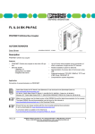
4.6
Typical structure of an Inline station with 24 V voltage area and a relay
terminal
Bus couplers
Various input/output terminals for the 24 V AC area
Relay terminal between distance terminals
Power terminal for the 24 V DC area
Various input/output terminals for the 24 V DC area
Electronics Base and Connectors
Low-level signal terminals and relay terminals are located in the same type of
housing, which is referred to as a low-level signal housing. An external
characteristic that distinguishes the base and the appropriate connectors for the
relay terminals from the base and connectors for the low-level signal terminals is
their color:
Area
Terminal
Connector
Other Differences
Low-level signal
(24 V DC)
Light gray
Light gray
Light color for function
identification (e.g., light blue)
Relay terminals (low
voltage; 230 V AC)
Dark gray
Dark gray
Light color for function
identification (e.g., light blue)
with white lightning bolt
Figure 4-2
Color of base and connectors
20/118
Bosch Rexroth AG | Electric Drives
and Controls
Inline | Application description
Important Information on Voltage Areas
4.7
Safety Mechanisms to Prevent Incorrect Connection of
Connectors for Different Voltage Areas
4.7.1
Protection Against the Connection of Connectors of the
24-V-Level to Relay Terminals
The low-level signal connectors can be plugged into relay terminals. Because the
relay outputs are floating, this connection error has no negative effects.
4.7.2
Protection Against the Connection of Live 230-V-AC- Connectors
in the 24 V DC Area
In the low-voltage area, live connectors can be connectors for the relay terminals.
These connectors are closed using filler plugs at some places and, therefore, do
not fit on the terminals of the 24-V-area.
4.8
Response to the Connection of a Relay Terminal in the
24-V-DC Area
A relay terminal can be inserted in the 24 V DC area. This does not result in direct
danger to people.
The module has no diagonal routing, so there is no direct danger from the
terminal, even with a 230 V connector. This means that the shortest isolating
distance is the distance from one connector to the next. This isolating distance is
not permitted. Therefore, insert a distance terminal (type: R-IB IL DOR LV-SET)
before and after the relay terminal.
Application description | Inline
Electric Drives | Bosch Rexroth AG
and Controls
21/118
Inline Product Groups
5
Inline Product Groups
The following sections give you an overview of the Inline product groups. For
specific information on the individual terminals, please refer to the terminalspecific data sheets and the individual sections in this application description.
5.1
General
5.1.1
Different Transmission Speeds
Inline terminals are available for transmission speeds of 500 kbps and 2 Mbps.
The order designation specifies the transmission speed.
Example:
500 kbps:
R-IB IL 24 DI 4
2 Mbps
R-IB IL 24 DI 4-2MBD
Please note that you can only work with one transmission speed
within a bus system.
CAUTION
You can identify terminals by means of the function identification (see "Function
Identification and Labeling" on page 36).
5.1.2
Products With or Without Accessories
Inline terminals are available with or without accessories. The order designation
specifies the scope of supply.
Example:
Without
accessories:
R-IB IL 24 DI 4
Including
accessories:
R-IB IL 24 DI 4-PAC
In the case of PAC products, Inline connectors and labeling fields are included in
the scope of supply.
22/118
Bosch Rexroth AG | Electric Drives
and Controls
Inline | Application description
Inline Product Groups
5.2
Bus Couplers and Terminals With Remote Bus Branch
5.2.1
Bus Couplers
A bus coupler is needed to connect an Inline station to a bus. The following bus
couplers were available when this application description was ready for printing:
Bus Coupler
Bus System
R-IBS IL 24 BK-T/U
R-IBS IL 24 BK-DSUB
INTERBUS
R-IL PB BK
R-IL PB BK DP/V1
R-IL PB BK DI8 DO4
PROFIBUS-DP
R-IL DN BK
DeviceNET
R-IL CAN BK-TC
CANopen
Figure 5-1
Bus couplers for different bus systems
The product range is continuously growing. More information on the
range can be found on the Internet at www.boschrexroth.com.
The different bus couplers are described in separate documents.
Not every Inline terminal can be operated with every bus coupler. For
an overview of the compatibility between Inline terminals and bus
couplers for various bus systems, please see "DOC-CONTRLILIOLIST***-KB..-EN-P".
Application description | Inline
Electric Drives | Bosch Rexroth AG
and Controls
23/118
Inline Product Groups
5.2.2
Terminal With Remote Bus Branch
If permitted by your bus system, this terminal can be used to create a remote bus
branch from the Inline station. This enables further segmentation of the system
so that, for example, star structures can be created. This terminal can be used to
switch the connected remote bus branch on or off.
The remote bus branch modules do not count as Inline station modules.
Terminals with remote bus branch can only be placed directly behind a bus
coupler or a terminal with remote bus branch.
This means that there must be no INTERBUS devices (no terminals with
protocol chip/ID code) between the bus coupler and the terminal with remote bus
branch.
Observe the restrictions of your bus system or bus coupler with regard
to terminals with remote bus branch.
5 5 2 0 B 0 7 4
Figure 5-1
Terminal with remote bus branch: R-IBS IL 24 RB-T
24/118
Bosch Rexroth AG | Electric Drives
and Controls
Inline | Application description
Inline Product Groups
5.3
Supply Terminals
Power terminals and segment terminals are available to supply the station with
I/O voltage. The segment terminals complement the power terminals. The
segment terminals make it possible to create different segments within a main
circuit.
Different types can be used to meet your requirements:
Designation
Type
R-IB IL 24 PWR IN
R-IB IL 24 PWR IN/R
R-IB IL 24 SEG/F
R-IB IL 24 SEG/F-D
Figure 5-2
Power terminal
Segment
terminal
Supply/
Provision
Fuse
Diagnostics
(INTERBUS
Device)
Fused Area
UM/US
No
No
None
U24V (UL/UANA)/
No
UM/US
No
None
US
Yes
No
Yes
Segment circuit
Overview of the supply terminals
Protect the power supply.
Protect the voltage supply externally, regardless of the supply terminal used.
CAUTION
Do not replace terminals while the power is connected.
Make sure power to the entire station is disconnected before removing a
terminal. Make sure the entire station is reassembled before switching the power
back on.
CAUTION
Application description | Inline
Electric Drives | Bosch Rexroth AG
and Controls
25/118
Inline Product Groups
5.3.1
Power Terminal
A power terminal is used to supply the required voltages to the internal station
potential jumpers. Several supply terminals can be used in one station. This
means that different circuits can be electrically isolated.
All power terminals are used to supply the main voltage and/or segment voltage.
5 5 2 0 A 0 1 3
Figure 5-2
Example of a power terminal: R-IB IL 24 PWR IN
Potential jumpers
The power terminal interrupts all potential jumpers for the voltages to be
reinjected, and recreates all potential jumpers (see also "Electrical Potential and
Data Routing" on page 47).
Carrying capacity of the
jumper contacts
The maximum load capacity of the jumper contacts on the side is indicated in
"Current and Voltage Distribution" on page 58.
Electrical isolation
The power terminal is used to create electrically isolated I/O areas within a
station.
Functional earth ground
connection
24 V terminals are connected to the functional earth ground when they are
snapped onto the grounded DIN rail via the FE spring on the bottom side of the
terminal. This spring is connected to the FE potential jumper and to the terminal
points for an FE connection.
If the previous terminal is a 24 V terminal, the power terminal is connected to the
FE potential jumper of the station when snapped onto this terminal.
26/118
Bosch Rexroth AG | Electric Drives
and Controls
Inline | Application description
Inline Product Groups
5.3.2
Segment Terminal
Segment terminals can only be used in the 24 V DC area. Segment terminals are
used to create partial circuits (segment circuits) within the main circuit.
On segment terminals without a fuse, the connection between the main circuit UM
and the segment circuit US must be established using a jumper or a switch.
Segment terminals with a fuse establish this connection automatically.
5 5 2 0 A 0 1 4
Figure 5-3
Example of a segment terminal: R-IB IL 24 SEG
UM
The potential jumper for the main circuit UM is not interrupted in the segment
terminal. The potential for the segment circuit US is tapped from the potential
jumper at the segment terminal.
US
The segment terminal interrupts the segment circuit US in the potential jumper of
the previous terminal.
For further information on the supply voltages, please refer to "Circuits and
Provision of Supply Voltages" on page 47.
Carrying capacity of the
jumper contacts
The maximum load capacity of the jumper contacts on the side is indicated in
"Current and Voltage Distribution" on page 58.
Functional earth ground
connection
The terminal is connected to the functional earth ground when it is snapped onto
the grounded DIN rail via the FE spring on the bottom side of the terminal. This
spring is connected to the FE potential jumper and to the terminal points for an
FE-connection.
When mounting a segment terminal onto the previous terminal, this segment
terminal is connected to the potential jumper FE of the station.
Application description | Inline
Electric Drives | Bosch Rexroth AG
and Controls
27/118
Inline Product Groups
5.4
Input/Output Terminals
5.4.1
General Information on Terminals for Analog and Digital Signals
For low-level signals, terminals with different functions are available. This
includes, for example, input/output terminals for analog and digital signals,
counter terminals and positioning terminals.
These terminals are available in different sizes. This enables you to set up the
station in a modular way so that it meets your application requirements.
Input/output terminals for digital signals and terminals with floating SPDT relay
contacts are available for the low voltage level.
5 5 2 0 A 0 1 5
Figure 5-4
Example of a digital input terminal: R-IB IL 24 DI 8
Protection
Overload protection of the system is centrally provided by a fuse in the power
terminal or by an external fuse provided by the user. The rating of the
preconnected fuse must be such that the maximum load current is not exceeded.
For the maximum permissible load current of an I/O terminal, please refer to the
terminal-specific data sheet.
Carrying capacity of the
jumper contacts
The maximum load capacity of the jumper contacts on the side is indicated in
"Current and Voltage Distribution" on page 58.
Grounding (FE)
Connection to functional earth ground (24 V DC area) is provided via the potential
jumpers when the terminal is snapped onto the previous terminal.
Voltage area
Input/output terminals are available for the 24 V DC voltage area.
28/118
Bosch Rexroth AG | Electric Drives
and Controls
Inline | Application description
Inline Product Groups
5.4.2
Terminals for Analog Signals
Shielding
Parameterization
The connectors of analog terminals have a special shield connection to shield the
cables.
Terminals for analog signals are in a preset configuration upon delivery.
Some terminals may also be parameterized to other configurations using the
output data words. Please refer to the terminal-specific data sheet to see if a
specific analog terminal can be configured and how the output data words are
assigned.
Data formats
Diagnostics in the input data
word
The measured values and the corresponding output values of terminals for
analog signals can be represented in different data formats depending on the
terminal used and on its configuration. These formats are listed in the terminalspecific data sheets.
Analog input terminals have overrange detection in all measuring ranges.
Open circuit is indicated in the 4 mA - 20 mA range.
Open circuit is also reported when using terminals for connecting thermocouples
and resistive temperature sensors.
Extended diagnostics
5.5
Some data formats support extended diagnostics. To determine whether
extended diagnostics are available for a specific terminal, please refer to the
terminal-specific data sheet.
Function Terminals (Communication, Open and ClosedLoop Control)
Function terminals are available to meet the following requirements:
•
•
•
•
•
Counting (R-IB IL CNT)
Positioning (e.g., R-IB IL SSI, R-IB IL INC)
Integrating V.24 devices
(R-IB IL RS 232-PRO, R-IB IL RS 485/422-PRO)
Pulse width modulation (R-IB IL PWM/2)
Temperature controller (R-IB IL TEMPCON UTH, R-IB IL TEMPCON RTD)
Please refer to the corresponding data sheet or application
description for information on these terminals.
Application description | Inline
Electric Drives | Bosch Rexroth AG
and Controls
29/118
Inline Product Groups
5.6
Branch Terminal
A branch terminal is available for integrating a Fieldline modular local bus in an
Inline station.
This terminal can be used to integrate sensors and actuators in close proximity to
the station, which are connected to the Fieldline modular local bus with
IP65/67 protection, in your bus system. Only use the branch terminal as the last
terminal in an Inline station.
Please refer to the corresponding data sheet for information on this
terminal.
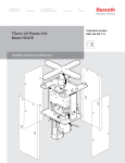
5.7
Example Structure of an Inline Station
4
1
3
2
1
7290A018
Figure 5-5
Example station with 24-V-DC-terminals
The example Inline station shown in Figure 5-5 consists of the following elements:
1
2
3
4
End clamp
Bus coupler (here, basic representation of a bus coupler with optional voltage
supply)
24 V DC terminals (e.g., I/O terminal)
End plate (end of the station)
30/118
Bosch Rexroth AG | Electric Drives
and Controls
Inline | Application description
Notes
5.8
Inline Block IO Modules
Block IO modules are available for inputting and/or outputting digital and analog
signals to various bus systems. Modules are available for the following bus
systems: INTERBUS, PROFIBUS-DP, DeviceNET, and CANopen.
The product range is continuously growing. More information on the
range can be found in the latest online product catalog at
www.boschrexroth.com.
Application description | Inline
Electric Drives | Bosch Rexroth AG
and Controls
31/118
Structure and Dimensions of the Inline Terminals
6
Structure and Dimensions of the Inline Terminals
6.1
Basic Structure of Terminals
Independent of function and design width, an Inline terminal consists of the
electronics base and the snap-in-place connector.
ZBFM labeling field for connector
Transparent field
Back connector
shaft latching
Keyway for attaching labeling field
Signal terminals 1/2
Potential terminals
Diagnostic an status
indicators
FE or Signal terminals 3/4
Colored
function encoding
D
1
Back
snap-on mechanism
2
3
4
4
DI
Connector
Front connector shaft latching
Electronics base
Slot encoding
Data jumpers
(knife contacts)
Front snap-on mechanism
Potential jumpers
(knife contacts)
Latching on
DIN rail
Feather of
keyway/featherkey connection
Figure 6-1
7290A011
Basic Inline terminal structure
The components shown in Figure 6-1 are described in the following sections.
The components required for labeling are listed in "Ordering Data" on
page 103.
32/118
Bosch Rexroth AG | Electric Drives
and Controls
Inline | Application description
Structure and Dimensions of the Inline Terminals
6.2
Electronics Base
The electronics base holds the entire electronics for an Inline terminal and the
potential and data routing.
Potential and data routing
Potential and data routing are located in the base. As all terminals are snapped
onto the DIN rail, the position of the interfaces between the terminals with regard
to the DIN rail is the same for all terminals (see also Figure 7-2 on page 55). The
advantage of this is that terminals of different sizes can be integrated into the
station.
The knife contacts are located on the left-hand side of the terminal (shown in
Figure 6-1). They snap into the featherkeys of the next terminal on the left when
the station is mounted.
The type of routing contacts (i.e., potential or data) that are on each terminal
depends on the function of the terminal and is shown in the circuit diagram of each
terminal-specific data sheet.
6.3
Snap-on mechanism/
latching
Pressing the front and back snap-on mechanism at the same time releases the
latching, enabling the terminal to be removed by pulling it straight back from the
DIN rail (see "Mounting and Removing Inline Terminals" on page 68).
Keyway/featherkey
connection
The featherkeys are on the left-hand side of the terminal (Figure 6-1). They snap
into the keyways of the next terminal on the left when the terminal is mounted on
the DIN rail. The featherkeys are also referred to as locking clips and the keyways
as guideways.
Base colors
The base and the appropriate connectors for the different voltage areas are of
different colors (see "Electronics Base and Connectors" on page 19).
Connectors
The I/O or supply voltages are connected using a pluggable connector.
Connector width
Regardless of the width of the electronics base, the connectors have a width of
two terminal points (connection points). This means that you must plug one
connector on a 2-slot base, two connectors on a 4-slot base, and four connectors
on an 8-slot base.
Connector colors
To distinguish between the functions and voltage areas, the connectors have
been assigned different colors:
Light gray
Connectors for low-level signal (24 V DC) terminals (excluding
supply terminals)
Black
Connectors for low-level signal supply terminals (24 V DC)
Dark gray
Connectors for relay terminals
Application description | Inline
Electric Drives | Bosch Rexroth AG
and Controls
33/118
Structure and Dimensions of the Inline Terminals
Connector types (24 V DC)
The following connector types are available for the 24 V DC area:
A
B
C
D
6 4 5 2 A 0 0 8
Figure 6-2
A
Relay-module connector
Connector types for Inline terminals
Standard connector
The light gray standard connector is used for the connection of two signals
in 4-wire technology (e.g., digital input/output signals).
The black standard connector is used for supply terminals. Some of the
adjacent contacts are jumpered internally (see Figure 6-3 on page 35).
B
Shield connector for connecting one cable
C
Shield connector for connecting two cables
Light gray connectors B and C are used for signals connected using
shielded cables (e.g., analog input/output signals, high-frequency counter
inputs, remote bus cable).
FE or shielding is connected by a shield connection clamp rather than by a
terminal point.
D
Extended double signal connector
This light gray connector is used for the connection of four signals in 3-wire
technology (e.g., digital I/O signals).
Dark gray standard connectors are available for the relay modules.
34/118
Bosch Rexroth AG | Electric Drives
and Controls
Inline | Application description
Structure and Dimensions of the Inline Terminals
Connector identification
All connectors are offered with and without color print. The connectors with color
print (marked with CP in the order designation) have terminal points that are colorcoded according to their functions.
The following colors indicate the signals of the terminal points:
Color
Terminal Point Signal
Red
+
Blue
-
Green
Functional earth ground (FE)
Green/yellow
Functional earth ground (FE);
This marking may still be seen on older connectors. Functional earth
ground is marked in green on modern connectors.
Figure 6-1
Terminal point color-coding (24 V DC)
The connectors for distance terminals are color-coded with two
colors.
The green marked side must point in the direction of the 24 V area and
the gray marked side in the direction of the AC area.
Application description | Inline
Electric Drives | Bosch Rexroth AG
and Controls
35/118
Structure and Dimensions of the Inline Terminals
Special features and internal
jumpering
A
1
B
2
1
C
2
1
D
2
1
E
2
1
2
1
1
1
1
1
1
1
1
1
1
2
2
2
2
2
2
2
2
2
2
3
3
3
3
3
3
3
3
3
3
4
4
4
4
4
4
4
4
4
4
5
5
6
6
7290A028
Figure 6-3
A
B
C
D
E
Internal jumpering within 24 V DC connectors
Light gray connector for I/O connection
Black connector for providing the supply voltages
Light gray shield connector for the connection of shielded cables
Light gray double signal connector for I/O connection
Dark gray connector for relay terminals
Terminal point without metal contact
The shield connector is jumpered between terminal points 1.4 and 2.4 through the
shield connection as seen in Figure 6-3. All other connectors are jumpered
internally through the terminal point connections in the connector.
Only install the appropriate connectors.
To avoid a malfunction, only snap a connector on a terminal that is appropriate
for this connector. Refer to the terminal-specific data sheet to select the correct
connectors.
CAUTION
Only place black connectors on supply terminals.
When the terminal points are jumpered in the black connector, power is carried
through the jumpering in the connector and not through the printed circuit board
of the terminal. The complete current carrying capacity is ensured through this
jumpering.
The black connector must not be placed on a terminal that is to be used for a
double signal connector. Incorrect connection may lead to a short circuit
between two signal terminal points.
36/118
Bosch Rexroth AG | Electric Drives
and Controls
Inline | Application description
Structure and Dimensions of the Inline Terminals
6.4
Function Identification and Labeling
Housing
The basic fields of application for terminals can be identified by their housing
color.
Field of Application
Housing Type
Housing
Color
Connector
Color
Low-level signal
terminals (24 V DC)
Low-level signal
housing
Light gray
Light gray/black
Relay terminals
Low-level signal
housing
Dark gray
Dark gray
Figure 6-2
Function identification
Field of application and housing
The terminals are color-coded to enable visual identification of the functions
(1 in Figure 6-4).
1
5 5 2 0 B 0 7 5
Figure 6-4
Function identification
The following colors indicate the functions:
Color
Terminal Function
24 V DC area
Gray
Bus coupler
Black
Power terminal/segment terminal
Light blue
Digital input
Pink
Digital output
Green
Analog input
Yellow
Analog output
Orange
Function terminal/control terminal
Relay terminal
Red with
lightning bolt
Figure 6-3
Digital output
Terminal color-coding
Application description | Inline
Electric Drives | Bosch Rexroth AG
and Controls
37/118
Structure and Dimensions of the Inline Terminals
Terminals with a transmission speed of 2 Mbps are identified by a white stripe at
the level of the D LED.
Identification of transmission
speed
500 kbps
2 Mbps
D
2
1
3
1
3
4
4
DO 4
Identification of transmission speed
The color-coding of the terminal points is described on page 34.
Connector identification
Terminal point numbering is explained using the example of an 8-slot terminal.
Labeling/terminal numbering
1
7290B003
DO 4
Figure 6-5
A
D
2
3
2
1
4
1
B
1
C
2
1
2
1
2
1
2
1
1 1
1 1
1 1
1
2
2 2
2 2
2 2
2
3
3 3
3 3
3 3
3
4
4 4
4 4
4 4
4
D
1
4
3
2
4
2
1 .1
1
1
2 .1
1 .2
2
2
2 .2
1 .3
3
3
2 .3
4
4
2 .4
1 .4
3
2
1
2
1
2
1
2
1
2
1
2
1
2
1
2
1
2
1 .1
2 .1
1 .1
2 .1
1 .1
2 .1
1 .1
2 .1
1 .1
2 .1
3 .1
4 .1
5 .1
6 .1
7 .1
8 .1
1 .2
2 .2
1 .2
2 .2
1 .2
2 .2
1 .2
2 .2
1 .2
2 .2
3 .2
4 .2
5 .2
6 .2
7 .2
8 .2
1 .3
2 .3
1 .3
2 .3
1 .3
2 .3
1 .3
2 .3
1 .3
2 .3
3 .3
4 .3
5 .3
6 .3
7 .3
8 .3
1 .4
2 .4
1 .4
2 .4
1 .4
2 .4
1 .4
2 .4
1 .4
2 .4
3 .4
4 .4
5 .4
6 .4
7 .4
8 .4
X .Y
6 4 5 2 A 0 2 6
Figure 6-6
Slot/connector
Terminal numbering
The slots (connectors) on a base are numbered consecutively (A in Figure 6-6).
This numbering is not shown on the terminal.
38/118
Bosch Rexroth AG | Electric Drives
and Controls
Inline | Application description
Structure and Dimensions of the Inline Terminals
Terminal point
Depending on your requirements you may order connectors with different
terminal point labeling:
1 Connectors without labeling (diagram on the left-hand side in Figure 6-6):
The terminal points on these connectors are marked X.Y.
X is the number of the terminal point row on the connector. It is indicated above
the terminal point row (B).
Y is the terminal point number in the terminal point row. It is directly indicated on
the terminal point (C).
The precise designation for a point is thus specified by the slot and terminal point.
The highlighted (gray) terminal point (D) would be numbered as follows: Slot 3
terminal point 2.3 (3.2.3).
2
Connector with printed terminal point numbering for each connector (middle
diagram in Figure 6-6):
Here, the terminal points are numbered as described above. The numbers are
printed above the terminal point.
3
Connector with printed terminal point numbering for each channel (diagram
on the right-hand side in Figure 6-6):
For terminals with eight or sixteen inputs or outputs, connector sets are available,
in which the terminal point rows are numbered by terminal (1 to 8) rather than by
connector (1 and 2). The numbers are printed above the terminal point.
Use the information provided in the terminal-specific data sheet to
select the connectors you require.
Application description | Inline
Electric Drives | Bosch Rexroth AG
and Controls
39/118
Structure and Dimensions of the Inline Terminals
Additional labeling
In addition to this terminal designation, you can identify the slots, terminal points,
and connections using labeling fields.
2
1
D
1
2
3
4
4
DI
7290A036
Figure 6-7
Labeling
Labeling fields are available in two widths, either as a labeling field covering one
connector (1; R-IB IL FIELD 2) or as a labeling field covering four connectors
(2; R-IB IL FIELD 8). You can label each channel individually with free text. On
the upper part of the connector there is a keyway for attaching this labeling field.
The labeling field can be tilted up and down. In each end position a light latching
ensures that the labeling field remains in place.
Using the markers on the connector and on the electronics base, you can clearly
assign both connector and slot.
Insert strips for use with a laser printer are available for insertion in the
R-IB IL FIELD 2 and R-IB IL FIELD 8 labeling fields (see "Ordering Data for
Accessories" on page 103).
40/118
Bosch Rexroth AG | Electric Drives
and Controls
Inline | Application description
Structure and Dimensions of the Inline Terminals
6.5
Housing Dimensions for Terminals
Today, small I/O stations are frequently installed in 80 mm standard control
boxes. Inline terminals are designed so that they can be used in this type of
control box.
The terminal dimensions are determined by the dimensions of the electronics
base and the dimensions of the connector.
The electronics base of the terminals is available in three standard design widths
(12.2 mm, 24.4 mm and 48.8 mm. They take one (1), two (2) or four (4), 12.2 mm
wide connectors.
When a connector is plugged in, each terminal has a depth of 71.5 mm.
The height of the terminal depends on the connector used. The connectors are
available in three different versions.
Dimensions of the Electronics Base
2-slot housing,
example:
R-IB IL 24 DO 2
R-IB IL 24 DI 4
(2 .8 1 5 ")
(4 .7 2 4 ")
7 1 ,5 m m
1 2 0 m m
6.5.1
1 2 ,2 m m
(0 .4 8 0 ")
Figure 6-8
5 5 2 0 A 0 2 3
Dimensions of the electronics base (2-slot housing)
Application description | Inline
Electric Drives | Bosch Rexroth AG
and Controls
41/118
Structure and Dimensions of the Inline Terminals
4-slot housing,
example:
R-IB IL AO 1/SF
R-IB IL CNT
(2 .8 1 5 ")
1 2 0 m m
(4 .7 2 4 ")
7 1 ,5 m m
2 4 ,4 m m
(0 .9 6 1 ")
Figure 6-9
5 5 2 0 C 0 2 2
Dimensions of the electronics base (4-slot housing)
8-slot housing,
example:
R-IB IL 24 DO 8
R-IB IL 24 DI 16
(2 .8 1 5 ")
1 2 0 m m
(4 .7 2 4 ")
7 1 ,5 m m
4 8 ,8 m m
(1 .9 2 1 ")
Figure 6-10
5 5 2 0 A 0 2 4
Dimensions of the electronics base (8-slot housing)
42/118
Bosch Rexroth AG | Electric Drives
and Controls
Inline | Application description
Structure and Dimensions of the Inline Terminals
Container housing 1,
example:
R-IBS IL 24 BK-DSUB
R-IL PB BK
1 2 0 m m
(4 .7 2 4 ")
7 1 ,5 m m
(2 .8 1 5 ")
9 0 m m
(3 .5 4 3 ")
Figure 6-11
3 3 ,5 m m
(1 .3 1 9 ")
6 4 5 2 A 0 1 9
Dimensions of the electronics base (container housing 1)
Application description | Inline
Electric Drives | Bosch Rexroth AG
and Controls
43/118
Structure and Dimensions of the Inline Terminals
6.5.2
Connector Dimensions
Connector
B
3
4
4
1
1
2
2
3
3
4
1
2
(5 .3 9 4 ")
3
2
1
1
2
3
4
4
2
1
1
2
2
2
3
4
1
1 3 7 m m
2
D
(5 .2 9 5 ")
2
1
1 3 4 ,5 m m
2
1
1 1 2 ,4 m m
C
(5 .1 9 7 ")
1
1
1 3 2 m m
(4 .4 2 5 ")
A
3
3
4
4
5
6
1 2 ,2 m m
(0 .4 8 0 ")
1 2 ,2 m m
(0 .4 8 0 ")
1 2 ,2 m m
(0 .4 8 0 ")
5
6
1 2 ,2 m m
(0 .4 8 0 ")
6 4 5 2 A 0 0 9
Figure 6-12
Connector dimensions
Key:
A
Standard connector (dimensions also apply to connector for relay
terminals)
B
Shield connector for connecting one cable
C
Shield connector for connecting two cables
D
Extended double signal connector
The depth of the connector does not influence the overall depth of the terminal.
44/118
Bosch Rexroth AG | Electric Drives
and Controls
Inline | Application description
Structure and Dimensions of the Inline Terminals
6.6
Mounting Distances
DIN rail
Inline terminals are always mounted onto DIN rails.
The distance between DIN rail fasteners must not exceed 200 mm. This distance
is necessary for the stability of the rail when mounting and removing Inline
terminals.
Mounting Distances
7 5 m m
(2 .9 5 3 ")
6 0 m m
(2 .3 6 2 ")
3 0 m m
(1 .1 8 1 ")
6 0 m m
(2 .3 6 2 ")
1 9 0 m m
(7 .4 8 0 ")
6.6.1
4 0 m m
(1 .5 7 5 ")
Figure 6-13
5 5 2 0 B 1 1 0
Mounting Distances
If the distances are smaller, the minimum bending radius of the
cables, easy handling during installation, and a clear structure cannot
be guaranteed.
Application description | Inline
Electric Drives | Bosch Rexroth AG
and Controls
45/118
Structure and Dimensions of the Inline Terminals
Mounting Distances for Mounting Outside a Terminal Box
If the Inline stations are housed in a control cabinet rather than a terminal box,
for example, the DIN rail distances depend on the previously mentioned mounting
distances.
1
D
2
1
D
2
D
2
D
E
1
PWR IN
DO2-2A
1
D
2
1
D
2
3
DO2-2A
4
DO4
DO2
40 mm
(1.578")
DO2-2A
160 mm
(6.299")
6.6.2
D
E
SEG-ELF
1
DI8
D
2
1
1
2
1
2
1
2
DI2
D
2
1
DI2
D
2
D
2RTD
7290A005
Figure 6-14
Mounting distances for mounting outside a terminal box
46/118
Notes
Bosch Rexroth AG | Electric Drives
and Controls
Inline | Application description
Application description | Inline
Electric Drives | Bosch Rexroth AG
and Controls
47/118
Electrical Potential and Data Routing
7
Electrical Potential and Data Routing
7.1
Circuits and Provision of Supply Voltages
There are several circuits within an Inline station. These are automatically created
when the terminals are properly installed. The voltages of the different circuits are
supplied to the connected terminals via potential jumpers.
An example of the circuits within an Inline station is given in "Example of a Circuit
Diagram" on page 52. The descriptions in the following sections refer to this
example.
Please refer to the terminal-specific data sheet for the circuit to
which the I/O circuit of a special terminal is to be connected.
Carrying capacity of the
jumper contacts
Observe the maximum current carrying capacity of the jumper contacts on the
side for each circuit. The current carrying capacities for all potential jumpers are
given in the following sections and are summarized in "Current and Voltage
Distribution" on page 58.
The arrangement of the potential jumpers and information on current and voltage
distribution on the potential jumpers can be found in "Electrical Potential and Data
Routing" on page 55.
The connection of the supply voltages is described in "Connecting the Voltage
Supply" on page 83.
For voltage connection, please refer to the notes given in the terminalspecific data sheets.
7.1.1
Supply of the Bus Coupler
Please refer to the documentation for your bus coupler to determine
the correct voltage supply for the bus coupler.
The voltages for the logic circuit UL and the supply of the terminals for analog
signals UANA are always internally generated from the bus coupler supply.
48/118
Bosch Rexroth AG | Electric Drives
and Controls
Inline | Application description
Electrical Potential and Data Routing
7.1.2
Logic Circuit
The logic circuit with the communications power UL starts at the bus coupler or at
a power terminal (R-IB IL 24 PWR IN/R) and is led through all terminals of an
Inline station.
Function
Voltage
The protocol chips for station devices are supplied with communications power
from the logic circuit.
The voltage in this circuit is 7.5 V DC ±5%.
Provision of UL
The communications power UL is provided from the bus coupler or a power
terminal from the connected supply voltage.
Current carrying capacity
The current carrying capacity is 2 A maximum (see technical data of the bus
coupler or power terminal). If this value is reached, the voltage must be reinjected
via a power terminal or a new station must be created using a bus coupler.
The current consumption from the logic circuit of each device is given in the Inline
device list and in every terminal-specific data sheet.
The communications power is not electrically isolated from the 24 V DC input
voltage for the bus coupler.
7.1.3
Analog Circuit
The analog circuit with the supply for the analog terminals (also known as analog
voltage) UANA starts at the bus coupler or at a power terminal
(R-IB IL 24 PWR IN/R) and is led through all terminals of an Inline station.
Function
Voltage
The I/O for analog signal terminals is supplied from the analog circuit.
The voltage in this circuit is 24 V DC (+20%, -15%).
Provision of UANA
The analog voltage UANA is provided from the bus coupler or a power terminal
from the connected supply voltage.
Current carrying capacity
The current carrying capacity is 0.5 A maximum (see technical data of the bus
coupler or power terminal). If this value is reached, the voltage must be reinjected
via a power terminal or a new station must be created using a bus coupler.
The current consumption from the analog circuit of each device that is supplied
from UANA is given in the Inline device list and in every terminal-specific data
sheet.
Application description | Inline
Electric Drives | Bosch Rexroth AG
and Controls
49/118
Electrical Potential and Data Routing
7.1.4
Main Circuit
The main circuit with the main voltage UM starts at the bus coupler or a power
terminal and is led through subsequent terminals until it reaches the next power
terminal.
Please note the special feature of Inline terminals with relay outputs.
These terminals interrupt the potential jumpers UM and US.
A new circuit starts at the next power terminal. This circuit is electrically isolated
from the previous one if electrically isolated power supply units are used.
Several power terminals can be used within one station.
Function
The segment voltage US can be tapped from the main voltage UM using different
segment terminals. Several independent segments can thus be created within the
main circuit. The main circuit provides the supply voltage for these segments.
Some terminals access the main circuit directly. For example, the encoder supply
for positioning terminals is tapped from the main circuit, while the I/O devices are
supplied from the segment circuit.
Voltage
Current carrying capacity
The voltage in this circuit should not exceed 30 V DC.
The maximum current carrying capacity for the main circuit is 8 A (total current
with the segment circuit).
This current carrying capacity can be reduced by certain terminals.
Please refer to the information in the terminal-specific data sheets.
If the limit value of the potential jumpers UM and US is reached (total current of US
and UM), a new power terminal must be used.
50/118
Bosch Rexroth AG | Electric Drives
and Controls
Inline | Application description
Electrical Potential and Data Routing
Provision of UM
In the simplest case, the main voltage UM can be supplied at the bus coupler.
The main voltage UM can also be supplied via a power terminal. A power terminal
must be used if:
1
2
3
4
7.1.5
A bus coupler that cannot supply the main voltage is used.
A new 24 V area is to be created downstream of a relay terminal.
Electrical isolation between different I/O areas is to be created.
The maximum current carrying capacity of the potential jumpers UM, US and
GND (total current of US and UM) is reached.
Segment Circuit
The segment circuit with segment voltage US starts at the bus coupler or a supply
terminal (power terminal or segment terminal) and is led through the subsequent
terminals until it reaches the next supply terminal.
Please note the special feature of Inline terminals with relay output.
These terminals interrupt the potential jumpers UM and US.
You can use several segment terminals within a main circuit and, therefore,
segment the main circuit.
Function
Almost all the terminals in the Inline station except the analog terminals are
supplied from the segment circuit (e.g., digital input terminals, digital output
terminals).
The segment circuit also provides the auxiliary supply voltage for controlling
power switches and contactors.
Some terminals access both the segment circuit and the main circuit. For
example, the encoder supply for positioning terminals is tapped from the main
circuit, while the I/O devices are supplied from the segment circuit.
The segment circuit can be switched off or fused using the safety or segment
terminals. It has the same reference ground as the main circuit. This means that
circuits with different fuses can be created within the station without external
cross wiring.
Voltage
Current carrying capacity
The voltage in this circuit should not exceed 30 V DC.
If the segment terminal and the preconnected power terminal do not have any
other limitations, the maximum current carrying capacity is 8 A (total current with
the main circuit). If the limit value of the potential jumpers UM and US is reached
(total current of US and UM), a new power terminal must be used.
Application description | Inline
Electric Drives | Bosch Rexroth AG
and Controls
51/118
Electrical Potential and Data Routing
Provision of US
There are various ways of providing the segment voltage US:
1
2
3
The segment voltage can be supplied at the bus coupler or a power terminal.
The segment voltage can be tapped from the main voltage at the bus coupler
or a power terminal using a jumper or a switch.
A power terminal with fuse can be used for the segment circuit. In this
terminal, the segment voltage is automatically tapped from the main voltage.
52/118
Bosch Rexroth AG | Electric Drives
and Controls
Inline | Application description
Electrical Potential and Data Routing
Example of a Circuit Diagram
M1
M2
S2.2
S2.1
R-IB IL 24 SEG/F
R-IB IL 24 PWR IN
S1.2
R-IB IL 24 SEG/F
S1.1
BK (+PWR IN)
7.1.6
Local bus
Protocol
chip
UL+
UANA
UL-
7,5 V
24 V
-U 1+
M
+
Figure 7-1
US
US
UM
UM
-
UM2
US
UM
+
-
7290A002
UBK
Potential routing within an Inline station
The illustrated Inline station is a typical example. It indicates the supply and
provision of different voltages and their forwarding via potential jumpers.
Explanations for this can be found in the following sections.
Application description | Inline
Electric Drives | Bosch Rexroth AG
and Controls
53/118
Electrical Potential and Data Routing
Mx
Sx, y
BK (PWR IN)
UBK
Main circuit (e.g., M1, M2)
Segment circuit y in main circuit x (e.g., S2.1, S2.2)
Bus coupler in conjunction with a power terminal, if required
Bus coupler supply (supply for bus coupler, generates UANA and UL)
UM
Main supply (I/O supply in the main circuit)
US
Segment supply (I/O supply in the segment circuit)
UANA
UL
Local bus
I/O supply for analog terminals
Communications power
Data jumper for the local bus
Ground (GND for the supply voltages UM and US)
Noiseless ground (functional earth ground, FE)
Protective earth ground
I
Main circuit M1/segment S1.1
Indicates the interruption of a potential jumper
The supply voltage for the bus coupler UBK is provided at the bus coupler (BK).
In addition, the main voltage UM1 is supplied at the bus coupler or a subsequent
power terminal.
The supply voltage of the logic UL and the supply voltage of the analog terminals
UANA are generated from the bus coupler supply and are led through the entire
station.
Electrical isolation between logic and I/O is provided through the separate supply
of the bus coupler supply UBK and the main voltage UM1.
If these voltages are not supplied separately (i.e., only the voltage
UM1, from which UL and UANA are also generated, for example) there
is no electrical isolation between logic and I/O.
No terminals are used in segment S1.1.
Segment S1.2
In a segment terminal with fuse, the segment voltage US for segment S1.2 is
automatically tapped from the main voltage UM1. This segment circuit is protected
by the internal fuse.
This segment terminal has been specifically used to create a
protected segment circuit without the need for additional external
fusing. If this is not necessary, the terminal does not have to be used.
In this case, the connection between UM and US on the bus coupler
must be established using a jumper (as shown on the R-IB IL
24 PWR/IN terminal) or a switch.
54/118
Bosch Rexroth AG | Electric Drives
and Controls
Inline | Application description
Electrical Potential and Data Routing
Main circuit M2/segment S2.1
The supply voltage for the power-level terminals and the subsequent terminals
should be provided separately. For this, a new power terminal
(e.g., R-IB IL 24 PRW/IN) is used, which provides the supply voltage UM2.
Using a jumper, the segment voltage US for segment S2.1 is tapped from the
main voltage UM2 at this terminal.
Segment S2.2
Segment terminal R-IB IL 24 SEG provides the segment voltage US via a switch.
Output terminals installed here can, therefore, be switched externally.
Errors and their effects
In this example structure, a short circuit in segment S1.2 or segment S2.2 would
not affect the terminals in other segments. The fuse in segment terminal
R-IB IL 24 SEG/F means that only segment S1.2 is switched off.
Application description | Inline
Electric Drives | Bosch Rexroth AG
and Controls
55/118
Electrical Potential and Data Routing
7.2
Electrical Potential and Data Routing
7.2.1
Arrangement of Potential Jumpers and Data Jumpers
An important feature of Inline is its internal potential routing system. The electric
connection between the individual station devices is created automatically when
the station is installed. When the individual station devices are connected, a
power rail is created for the relevant circuit. Mechanically, this is created by
interlocking knife and featherkey contacts from the adjacent terminals.
This potential routing eliminates the need for additional external potential
jumpering or cross wiring.
UL+ UANA UL- US UM
1
2
3
4
5
UM US UL-UANAUL+
6
7
7
6
5
4
3
A
8 Local bus
Figure 7-2
2
1
B
9
9
Arrangement of the potential and data jumpers
Local bus
8
7290A108
56/118
Bosch Rexroth AG | Electric Drives
and Controls
Inline | Application description
Electrical Potential and Data Routing
No.
Function
Meaning
See Figure 7-2 "Arrangement of the potential and data jumpers" on page 55
Potential jumpers
1
7.5 V DC
UL+
Communications power for the bus interface
2
24 V DC
UANA
I/O supply for analog terminals
3
GNDL
UL-
Ground of communications power and I/O supply for analog terminals
4
24 V DC
US
Supply of the segment circuit
(if necessary with overload protection)
5
24 V DC
UM
Supply of the main circuit
(if necessary with overload protection)
6
GND
GND
Ground of segment and main supply
7
FE
FE
Functional earth ground
(9)
FE spring
FE contact to the DIN rail
(for bus couplers, segment terminals, and power terminals for the SELV area)
Data jumper
8
Figure 7-1
Local bus
Potential and data jumpers (24 V DC area)
Terminal inputs and outputs are supplied with voltage via the segment
circuit.
The voltage for the segment circuit can be tapped from the main
circuit. In addition, some terminals tap the voltage directly from the
main circuit.
For further information on circuits that are created via the potential
jumpers UL, UANA, UM, and US, please refer to page 47.
Depending on the terminal function, not all of the jumpers listed in
Figure 7-2 are present in a terminal. Please refer to the circuit
diagram of the terminal to see which jumpers are provided for a
terminal and how they are internally connected. The circuit diagram is
shown in the terminal-specific data sheet.
Application description | Inline
Electric Drives | Bosch Rexroth AG
and Controls
57/118
Electrical Potential and Data Routing
GND
This potential jumper is ground for the main and segment circuits.
Note that the GND potential jumper carries the total current of the main and
segment circuits. The total current of the main and segment circuits must not
exceed the maximum current carrying capacity of the potential jumpers (8 A).
The maximum current carrying capacity is determined not only by the potential
jumpers, but also by the power/segment terminals used.
CAUTION
Refer to the data provided in the terminal-specific data sheet for your
particular application.
FE
The FE potential jumper must be connected via the corresponding connection at
the bus coupler to a grounding terminal. In addition, the FE potential jumper is
connected via the FE spring to the grounded DIN rail of every supply terminal and
led through all of the terminals.
FE spring
The spring creates the FE contact between the bus coupler, a 24 V DC power
terminal or a segment terminal, and the grounded DIN rail.
Data routing
The bus signal is also transmitted within the station using a connection that is
created automatically when the station devices are snapped on.
Current carrying capacity
The maximum total current flowing through the potential jumpers is limited. The
maximum current carrying capacity is indicated for each circuit in "Circuits and
Provision of Supply Voltages" on page 47.
Please refer to the information on the current carrying capacity of the
power and segment terminals provided in the terminal-specific data
sheets.
CAUTION
If the current carrying capacity of the potential jumpers UL or UANA is reached,
voltage must be reinjected via a power terminal, or a new station must be created
using a bus coupler
If the current carrying capacity of the potential jumpers UM, US and GND is reached
(total current of US and UM), a new power terminal must be used.
58/118
Bosch Rexroth AG | Electric Drives
and Controls
Inline | Application description
Electrical Potential and Data Routing
7.2.2
Current and Voltage Distribution
1 1 2 2
a
b
4 4
5 5
6 6
7 7
c
8 8
Figure 7-3
No.
3 3
5 5 52 50 2A 0 0B 5 07 5 7
( (9 9 ) )
Current and voltage distribution
Voltage to Contact1
Function
Current
Minimum
Maximum
Maximum
Potential jumpers
1
7.5 V DC
UL+
7.0 V DC
7.87 V DC
2A
2
24 V DC
UANA
19.2 V DC
30 V DC
0.5 A
0 V DC
2.5 A
3
GNDL
UL-
0 V DC
4
24 V DC
US
19.2 V DC
30 V DC
5
24 V DC
UM
19.2 V DC
30 V DC
6
GND
GND
0V
0V
8A
7
FE
FE
Not defined
Not defined
Not defined
(9)
FE spring
Data jumpers
8a
Bus signal
8b
Bus signal
8c
Clock
Figure 7-2
1
Current and voltage distribution in potential and data jumpers
Contact no. 3 is reference potential for the logic.
Contact no. 6 is reference potential for the I/O.
If there is no electrical isolation between logic and I/O, both have the same potential.
8A
Application description | Inline
Electric Drives | Bosch Rexroth AG
and Controls
59/118
Diagnostic and Status Indicators
8
Diagnostic and Status Indicators
All terminals are provided with diagnostic and status indicators for quick local
error diagnostics. They enable the clear localization of system errors (bus errors)
or I/O errors.
Diagnostics
The diagnostic indicators (red, yellow or green) provide information about the
status of the terminal and, in the event of an error, provide information about the
type and location of the error. A terminal is operating correctly if all its green LEDs
are on.
Status
The status indicators (yellow) display the status of the relevant input/output and
the connected device.
Extended diagnostics
Some Inline terminals have extended diagnostics. A short circuit or overload of
the sensor supply is indicated for each input. If a short circuit occurs at an output,
each channel is diagnosed individually. Information on the supply voltage is also
reported. Information on I/O errors is sent to the control system with the precise
identification of the error type and is displayed using status indicators.
Please refer to the terminal-specific data sheet for information about
the diagnostic and status indicators on each terminal.
8.1
Indicators on Bus Couplers and Terminals With Remote
Bus Branch
For the meaning of the diagnostic and status indicators of the bus
couplers and the terminals with remote bus branch, please refer to the
corresponding documentation.
60/118
Bosch Rexroth AG | Electric Drives
and Controls
Inline | Application description
Diagnostic and Status Indicators
8.2
Indicators Available on Different Terminals in the Inline
System
Some indicators can be found on various terminals and generally have the same
meaning:
UM
Green LED
Supply in the main circuit
ON:
Supply is present in the main circuit
OFF:
Supply is not present in the main circuit
Green LED
Supply in the segment circuit
ON:
Supply is present in the segment circuit
OFF:
Supply is not present in the segment circuit
D
Green LED
Diagnostics
(3)
ON:
Data transmission within the station is active
US
Flashing:
0.5 Hz:
(slow)
Communications power is present,
data transmission within the station is not active
2 Hz:
(medium)
Communications power is present,
I/O error is present
(e.g., fuse has blown, voltage is missing)
4 Hz:
(fast)
Communications power is present,
error at the interface between previous and flashing terminal (the terminals after the flashing
terminal cannot be addressed)
(e.g., loose contact at the bus interface, terminal before the flashing terminal has failed, another
terminal was snapped on during operation [not permitted])
OFF:
Communications power is not present
Application description | Inline
Electric Drives | Bosch Rexroth AG
and Controls
61/118
Diagnostic and Status Indicators
8.3
Indicators on Supply Terminals
1
1
UM
US
PWR IN
SEG
1
1
1
2
1
1
1
1
D
E
US
E
2
SEG/F
2
1
1
1
2
1
1
2
SEG/F-D
1
2
1
7290A029
Figure 8-1
Diagnostics
Possible indicators on supply terminals
The following states can be read on the supply terminals:
Power Terminal
UM (1)
Green LED
Supply voltage in the main circuit (for meaning see page 60)
Segment Terminal
US (1)
Green LED
Supply voltage in the segment circuit (for meaning see page 60)
Power Terminal With Fuse and Diagnostics/
Segment Terminal With Electronic Fuse
D (3)
Green LED
Diagnostics (for meaning see page 60)
Also on Supply Terminals With Fuse
E (2)
Red LED
Fuse status
ON:
Fuse not present or blown
OFF:
Fuse OK
On terminals with fuses, the green UM or US LED indicates that the
main or segment voltage is present at the line side of the fuse,
meaning that if the green LED is on, there is voltage on the line side
of the fuse. If the red E LED is also on, the fuse has blown or is
missing and no voltage is applied after the fuse.
If the red E LED is on and the green D LED is flashing at 2 Hz on
terminals with fuses and diagnostics, there is no voltage after the
fuse. Thus, a blown fuse is indicated by both diagnostic indicators.
The red E LED is on and the green D LED flashes at 2 Hz.
62/118
Bosch Rexroth AG | Electric Drives
and Controls
Inline | Application description
Diagnostic and Status Indicators
8.4
Indicators on Input/Output Terminals and Function
Terminals
The LEDs of the input/output terminals are electrically located in the logic area.
This may mean that the LED of an output is on but the output cannot be controlled
due to an error between the logic area and the digital output. The LED does not
monitor the output state. In the event of an error, the actual output state may differ
from the state indicated by the LED.
1
1
1
D
1
2
1
2
1
2
D
1
2
2
3
2
4
2
1
2
1
1
1 1
2
1
2
1 1
1
1 1
2
1
1
1
2
1
5 5 2 0 0 0 5 2
Figure 8-2
Diagnostics
D
I/O terminal indicators
The following states can be read on the I/O terminals:
Green LED
Diagnostics (for meaning see page 60)
(1)
Status
1, 2,
3, 4
(2)
The status of the input or output can be read on the relevant yellow LED:
Yellow LED
Status of the input/output
ON:
Corresponding input/output is set
OFF:
Corresponding input/output is not set
For terminals with extended diagnostics
E1, E2,
E3, E4
Yellow LED
The meaning depends on the terminal. It is described in the terminal-specific data
sheet, e.g.:
Initiator supply short circuit/overload
Output short circuit
Error message of the diagnostic input
ON:
An error has occurred
OFF:
No error
Function terminals
Diagnostic indicator D is located on all function terminals and has the same
function as described on page 60.
Additional diagnostic indicators can be found on the function
terminals. They are described in the corresponding documentation.
The various status indicators for the function terminals are also
described in the corresponding documentation.
Application description | Inline
Electric Drives | Bosch Rexroth AG
and Controls
63/118
Diagnostic and Status Indicators
Assignment Between Status LED and Input/Output
The figure shows the general principle of the assignment of a status LED to its
input or output.
1
1
2
D
1
2
1
2
D
1
2
1 /1
D
1
1
3
1
4 /2
1
2
2
3
4
3
4
4
D I1 6
D I4
2
4
2
3
4
4
1
1
2
3
3
D I 2
3
2
2
4
1
1 /3
2
1
2
1
2
1
4 /4
2
1
1
1
1
1
1 1
1 1
1 1
1
2
2
2
2
2
2 2
2 2
2 2
2
3
3
3
3
3
3 3
3 3
3 3
3
4
4
4
4
4
4 4
4 4
4 4
4
5
5
5
5 5
5 5
5 5
5
6
6
6
6 6
6 6
6 6
6
5 5 2 0 A 0 6 6
Figure 8-3
Assignment between status LED and input/output
Please refer to "Function Identification and Labeling" on page 36 for an
explanation of the numbering.
With an 8-slot terminal, the LEDs of a slot belong to the terminal points of this slot.
Every slot can be considered a 2-slot terminal.
For a 2-slot terminal with four inputs or outputs (example in the middle in
Figure 8-3), the following LEDs belong to the following terminal points:
LED 1
Terminal point 1.1
LED 2
Terminal point 2.1
LED 3
Terminal point 1.4
LED 4
Terminal point 2.4
On the 8-slot terminal in Figure 8-3 and Figure 8-4, e.g., with 4/2, LED 2 on slot 4
is indicated. The LED belongs to input 14 on terminal point 4.2.1 (slot 4, terminal
point 2.1).
64/118
Bosch Rexroth AG | Electric Drives
and Controls
Inline | Application description
Diagnostic and Status Indicators
1
1 /1
2
D
1
3
1
4
1
2
3
2
3
4
4 /2
1
2
2
3
4
3
4
4
D I1 6
1 1
1
1 1
2
1
1 1
2
4 /4
IN 1 3
IN 1 4
1
2
IN 9
IN 1 0
1
IN 1
IN 2
2
IN 5
IN 6
1
1 /3
1
2
3
3 3
3 3
3 3
3
4
4 4
4 4
4 4
IN 1 5
IN 1 6
2 2
IN 1 1
IN 1 2
2 2
IN 7
IN 8
2 2
IN 3
IN 4
2
5
5 5
5 5
5 5
5
6
6 6
6 6
6 6
6
4
6 4 5 2 A 0 3 4
Figure 8-4
Assignment between status LED and input/output using the example of an
R-IB IL 24 DI 16 terminal
For every terminal, the assignment is indicated in the terminal-specific
data sheet.
Application description | Inline
Electric Drives | Bosch Rexroth AG
and Controls
65/118
Mounting/Removing InlineTerminals and Connecting Cables
9
Mounting/Removing InlineTerminals and
Connecting Cables
9.1
Installation Instructions
9.1.1
Unpacking a Terminal
ESD Regulations
Electrostatic discharge
The terminal contains components that can be damaged or destroyed by
electrostatic discharge. When handling the terminal, observe the necessary
safety precautions against electrostatic discharge (ESD) according to
EN 61340-5-1 and EN 61340-5-2.
Unpacking the Terminal
The terminal is supplied in an ESD box.
Only qualified persons should pack, unpack, mount, and remove a terminal while
observing the ESD regulations.
9.1.2
Replacing Terminals
Do not replace terminals while the power is connected.
Before removing or mounting a terminal, disconnect power to the entire station.
Make sure the entire station is reassembled before switching the power back on.
WARNING
66/118
Bosch Rexroth AG | Electric Drives
and Controls
Inline | Application description
Mounting/Removing InlineTerminals and Connecting Cables
9.2
Sequence of the Inline Terminals
The sequence of the terminals within an Inline station should depend on the
current consumption of the I/O devices from the potential jumpers UM and US.
As the voltage at every power terminal is resupplied into the potential jumpers UM
and US, the section (main circuit) between a bus coupler and a power terminal or
between a power terminal and a power terminal must always be considered when
calculating the current. If power terminals are not used, the entire station is a main
circuit.
Within a main circuit, install the terminals according to their current
consumption. Install the terminals with the highest current consumption first. This
has the advantage that the high supply current does not flow through the entire
main circuit and thus does not flow through all the terminals.
This results in the following sequence:
1. Digital output terminals
2. Digital input terminals
3. Function terminals
4. Analog terminals
Power-level terminals may be placed anywhere in the main circuit before function
and analog terminals.
For the current consumption of the terminals, please refer to the
terminal-specific data sheet.
9.2.1
Remote Bus Branch in an Inline Station
If you want to integrate a remote bus branch into an Inline station, note that the
terminal with remote bus branch must be placed directly behind a bus terminal
or a terminal with remote bus branch.
Please refer to the corresponding data sheets to see if any other
special requirements should be noted.
Application description | Inline
Electric Drives | Bosch Rexroth AG
and Controls
67/118
Mounting/Removing InlineTerminals and Connecting Cables
9.2.2
Positioning Terminals for Analog Signals
High current flowing through potential jumpers UM and US leads to a temperature
rise in the potential jumpers and the inside of the terminal. This decreases the
measuring precision and shortens the life of the terminal.
Observe the following instructions to keep the current flowing through the
potential jumpers of the analog terminals as low as possible:
Create a separate main circuit for each analog terminal.
If this is not possible in your application and if you are using analog terminals in
a main circuit together with other terminals, place the analog terminals after all
the other terminals at the end of the main circuit.
CAUTION
Creating a separate main circuit means that
•
•
A main circuit is provided for all analog terminals or
Several main circuits are only provided exclusively for analog
terminals.
This also means that no terminals other than analog terminals should
be in a main circuit for analog terminals.
Within the analog terminals, position the
R-IB IL TEMP 2/UTH terminal behind all the other terminals to keep
the current flowing through all potential jumpers as low as possible.
68/118
Bosch Rexroth AG | Electric Drives
and Controls
Inline | Application description
Mounting/Removing InlineTerminals and Connecting Cables
9.3
Mounting and Removing Inline Terminals
Mounting location
DIN rail
Terminals of the Inline product range have IP20 protection and are therefore
suitable for use in closed control cabinets or control boxes (box for terminals) with
IP54 or higher.
All Inline terminals are mounted on 35 mm standard DIN rails.
The modules are mounted perpendicular to the DIN rail. This ensures that they
can be easily mounted and removed even within limited space.
Mounting side by side
An Inline station is set up by mounting the individual components side by side. No
tools are required. Mounting the components side by side automatically creates
the potential and bus signal connections between the individual station
components.
After a station has been set up, individual terminals can be exchanged by pulling
them out or plugging them in. Tools are not required.
End clamp
Mount end clamps on both sides of the Inline station. The end clamps ensure that
the Inline station is correctly mounted. End clamps fix the Inline station on both
sides and stop it moving from side to side on the DIN rail.
Bosch Rexroth recommends that SUB-M01 ENDHALTER
(MNR R911170685, pack of 2) are snapped on without tools.
End plate
The end plate terminates an Inline station. It has no electrical function. It protects
the station against ESD pulses and the user against dangerous voltages. The end
plate is supplied with the bus coupler and need not be ordered separately.
Mounting
When mounting a terminal, proceed as shown in Figure 9-1 on page 69:
•
•
Disconnect the power to the station.
First snap on the electronics base, which is required for mounting the station,
perpendicular to the DIN rail (detail A).
When doing this ensure that all featherkeys and keyways on adjacent
terminals are securely interlocked (B).
The keyway/featherkey connection links adjacent terminals together and
ensures that data and potential routing is created safely.
•
•
•
•
First, insert the data jumper for the bus interface in the guideways by
snapping it into the previous terminal (detail B1). Press gently against
the previous terminal to make sure that the featherkey has snapped
into its keyway on the bus interface.
Then insert the other potential jumpers into their guideways and snap the
featherkeys into the corresponding keyways (detail B2).
Detail C1 shows a common error. Here, the bus interface has not
contacted properly. The featherkey is not in the keyway. The bus is not
running or running with errors ("loose contact").
Detail C2 shows secure contacting of the data jumpers and the
interlocking keyway/featherkey connection.
Application description | Inline
Electric Drives | Bosch Rexroth AG
and Controls
69/118
Mounting/Removing InlineTerminals and Connecting Cables
•
Once all the bases have been snapped on, plug the connectors into the
appropriate bases.
First, place the front connector shaft latching in the front snap-on mechanism
(detail D1).
Then pivot the top of the connector towards the base until it snaps into the
back snap-on mechanism (detail D2).
The keyways of an electronics base do not continue when a
connector has been installed on the base. When snapping on an
electronics base, there must be no connector on the left-hand side of
the base. If a connector is present, it will have to be removed.
A
B
B1
C1
C
D
D2
B2
D1
C2
7290A010
Figure 9-1
Mounting a terminal
70/118
Bosch Rexroth AG | Electric Drives
and Controls
Inline | Application description
Mounting/Removing InlineTerminals and Connecting Cables
Removal
When removing a terminal, proceed as shown in Figure 9-2 on page 71:
•
•
Disconnect the power to the station.
If there is a labeling field, which covers several connectors, it may be
necessary to remove it (detail A1).
If a terminal has several connectors, all connectors of the terminal
must be removed. The following describes how a 2-slot terminal is
removed.
•
Lift the connector of the terminal to be removed by pressing on the back
connector shaft latching (detail A2).
Please ensure when using extended double signal connectors (long
connectors) that you do not bend the connectors back too far, as you
may break the front snap-on mechanism.
•
•
•
Remove the connector (detail B).
Remove the adjacent connectors of the neighboring terminals (detail C). This
prevents the potential routing knife contacts and the keyway/featherkey
connection from being damaged. You also have more space available for
accessing the terminal.
Press the snap-on mechanism (detail D1), and remove the electronics base
from the DIN rail by pulling the base straight back (detail D2). If you have not
removed the connector of the adjacent terminal on the left, remove it now in
order to protect the potential routing knife contacts and the featherkeys of the
keyway/featherkey connection.
Application description | Inline
Electric Drives | Bosch Rexroth AG
and Controls
71/118
Mounting/Removing InlineTerminals and Connecting Cables
A
A 2
B
A 1
C
D 1
D
D 1
Figure 9-2
Replacing a terminal
D 2
6 4 5 2 A 0 3 0
Removing a terminal
If you want to replace a terminal within the Inline station, follow the removal
procedure described above. Do not snap the connector of the adjacent terminal
on the left back on yet. Insert the base of the new terminal. Then reconnect all the
connectors.
Ensure that all featherkeys and keyways on adjacent terminals are
securely interlocked.
72/118
Bosch Rexroth AG | Electric Drives
and Controls
Inline | Application description
Mounting/Removing InlineTerminals and Connecting Cables
9.4
Replacing a Fuse
The 24 V DC power and segment terminals are also available in versions with a
fuse. If a fuse is not present or faulty, you must insert or replace it.
Observe the following notes when replacing a fuse for the
protection of your health and your system.
1.
2.
WARNING
Use the screwdriver carefully to avoid injury to yourself or other persons.
Lift the fuse out at the metal contact. Do not lift the fuse out at the glass part
as this may break it.
Carefully lift the fuse out at one side and remove it by hand. Make sure the fuse
does not fall into your system.
When replacing a fuse, proceed as shown in Figure 9-3 on page 73:
•
•
•
•
•
•
Lift the fuse lever (detail A).
Insert the screwdriver behind a metal contact of the fuse (detail B).
Carefully lift out the metal contact of the fuse (detail C).
Remove the fuse by hand (detail D).
Insert a new fuse (detail E).
Push the fuse lever down again until it clicks into place (detail F).
Application description | Inline
Electric Drives | Bosch Rexroth AG
and Controls
73/118
Mounting/Removing InlineTerminals and Connecting Cables
A
B
D
C
F
E
6 4 5 2 A 0 3 1
Figure 9-3
Replacing a fuse
74/118
Bosch Rexroth AG | Electric Drives
and Controls
Inline | Application description
Mounting/Removing InlineTerminals and Connecting Cables
9.5
Grounding Concept (Functional Earth Ground)
Only the functional earth ground is used within an Inline station.
Functional earth
grounding (FE)
Functional earth grounding is used to improve immunity to interference. All
devices must be grounded so that any possible interference from data
transmission paths is shielded and discharged to ground.
A wire of 1.5 mm2 (16 AWG) must be used for grounding spring-cage terminals.
Functional earth ground is a low-impedance path between electrical circuits and
ground. It is not designed as a safety measure but rather, for example, for the
improvement of immunity to interference.
Functional earth ground is only used to discharge interference. It does
not provide shock protection for people.
Functional earth ground is used within the 24 V DC area (SELV).
It is led from the grounded bus coupler or power terminal through the 24 V DC
area of the station using the FE potential jumper.
To ensure reliable functional earth grounding of the station, you must observe
various points.
1
Bus coupler, power terminals, and segment terminals have an FE spring
(metal clip) on the bottom of the electronics base. This spring creates an
electrical connection to the DIN rail. Use grounding terminals to connect the
DIN rail to protective earth ground. The terminals are grounded when they are
snapped onto the DIN rail.
2 It is also recommended that the bus coupler should be grounded using the
FE-terminal point to ensure reliable functional earth grounding even if the DIN
rail is dirty or the metal clip damaged (see terminal-specific data sheet).
The other Inline low-level signal terminals are automatically grounded via the FE
potential jumper when they are mounted adjacent to other terminals.
The FE potential jumper is looped through the relay terminals.
Application description | Inline
Electric Drives | Bosch Rexroth AG
and Controls
75/118
Mounting/Removing InlineTerminals and Connecting Cables
6 4 5 2 A 0 1 3
Figure 9-4
Diagram of the additional functional earth grounding of a bus coupler
Figure 9-4 shows the additional grounding of a standard bus coupler.
The additional grounding of a special bus coupler is shown in the
documentation for the bus coupler.
76/118
Bosch Rexroth AG | Electric Drives
and Controls
Inline | Application description
Mounting/Removing InlineTerminals and Connecting Cables
9.6
Shielding Concept
Shielding is used to reduce the effects of interference on the system.
9.6.1
Inline Shielding Concept
In the Inline system, remote bus cables and the cables to connect terminals for
analog signals are shielded.
Observe the following notes when installing shielding:
•
Fasten the shielding so that as much of the braided shield as possible is held
underneath the clamp of the shield connection.
•
Make sure there is good contact between the connector and base.
•
Do not damage or squeeze the wires. Do not strip more than 8 mm off the
wires.
9.6.2
Shielding Analog Sensors and Actuators
•
•
Always connect analog sensors and actuators with shielded, twisted pair
cables.
Connect the shielding via the shield connector. The method for connecting
the shielding is described in "Connecting Shielded Cables Using a Shield
Connector" on page 78.
When connecting the cables observe the instructions in the terminalspecific data sheets.
9.7
Connecting Cables
Shielded and unshielded cables are used in an Inline station.
The I/O devices, supply voltages, and bus cables are connected using the springcage connection method. This means that signals up to 250 V AC/DC and 5 A
can be connected with a conductor cross section of 0.2 mm2 to 2.5 mm2 (24 14 AWG).
Please note the sensor/actuator cable must be less than 30 m long.
Application description | Inline
Electric Drives | Bosch Rexroth AG
and Controls
77/118
Mounting/Removing InlineTerminals and Connecting Cables
Connecting Unshielded Cables
1
In p
ta l
ig i
9.7.1
1
2
6 4 5 2 B 0 3 2
Figure 9-5
Connecting unshielded cables
Wire the connectors as required for your application.
For the connector pin assignment, please refer to the appropriate
terminal-specific data sheet.
When wiring, proceed as follows:
•
Strip 8 mm off the cable.
Inline wiring is normally done without ferrules. However, it is possible
to use ferrules. If using ferrules, make sure they are properly crimped.
•
Push a screwdriver into the slot above the appropriate terminal point
(Figure 9-5, 1), so that you can plug the wire into the spring opening.
Bosch Rexroth recommends using a screwdriver with a 0.6 mm x 3.5 mm x
100 mm blade.
• Insert the wire (Figure 9-5, detail 2). Remove the screwdriver from the
opening. This clamps the wire.
After installation, you should always label the wires and the terminal points (see
also "Function Identification and Labeling" on page 36).
78/118
Bosch Rexroth AG | Electric Drives
and Controls
Inline | Application description
Mounting/Removing InlineTerminals and Connecting Cables
9.7.2
Connecting Shielded Cables Using a Shield Connector
Shielded cables can be connected via the R-IB IL SCN-6 SHIELD and
R-IB IL SCN 6-SHIELD-TWIN shield connectors. The R-IB IL SCN-6 SHIELD
shield connector is designed to connect one shielded cable. Two shielded cables
can be easily connected via the R-IB IL SCN 6-SHIELD-TWIN shield connector.
In principle, cables are connected via the shield connector in the same way as
shown in Figure 9-6 on page 80 and Figure 9-7 on page 81.
Figure 9-6 shows the connection of a shielded cable using a remote bus cable as
an example. In this example, the cables are twisted pair cables.
Figure 9-7 shows the connection of two shielded cables, using the wiring of the
R-IB IL AI 2/SF terminal as an example. As two channels can be used here, the
R-IB IL SCN 6-SHIELD-TWIN shield connector is used.
When connecting the cables proceed as shown in Figure 9-6 and Figure 9-7:
Stripping cables
•
•
•
•
•
Strip the outer cable sheath to the desired length (a). (Detail A)
The desired length (a) depends on the connection position of the wires and
whether the wires should have a large or small amount of space between the
connection point and the shield connection.
Shorten the braided shield to 15 mm. (Detail A)
Fold the braided shield back over the outer sheath. (Detail B)
Remove the protective foil.
Strip 8 mm off the wires. (Detail B)
Inline wiring is normally carried out without ferrules. However, it is
possible to use ferrules. If using ferrules, make sure they are properly
crimped.
When using twisted pair cables, keep the wire twisted until just before
the terminal point.
Application description | Inline
Electric Drives | Bosch Rexroth AG
and Controls
79/118
Mounting/Removing InlineTerminals and Connecting Cables
Wiring the connectors
•
•
Push a screwdriver into the slot above the appropriate terminal point
(Figure 9-5 on page 77, 1), so that you can plug the wire into the spring
opening.
Bosch Rexroth recommends using a screwdriver with a 0.6 mm x 3.5 mm x
100 mm blade.
Insert the wire (Figure 9-5 on page 77, detail 2). Remove the screwdriver from
the opening. This clamps the wire.
For the connector pin assignment, please refer to the appropriate
terminal-specific data sheet.
Connecting the shield
Figure 9-6 shows the shield connection for the R-IB IL SCN 6-SHIELD connector.
The procedure for the R-IB IL SCN 6-SHIELD-TWIN connector (shown in
Figure 9-7) is the same.
•
•
•
•
•
Open the shield connection (detail C).
Check the position of the shield connection clamp in the shield connection
(see also "Shield connection clamp" on page 82).
Place the cable with the folded braided shield in the shield connection
(detail D).
Close the shield connection (detail E).
Fasten the screws for the shield connection using a screwdriver. (Detail F)
To ensure that the shield connection clamp remains in place when the
shield connection is closed, first secure the shield clamp with screws
and then close the shield connection.
80/118
Bosch Rexroth AG | Electric Drives
and Controls
Inline | Application description
Mounting/Removing InlineTerminals and Connecting Cables
A
B
a
1 5 m m
(0 .5 9 ")
8 m m
(0 .3 1 ")
D
C
E
F
5 5 2 0 C 0 6 7
Figure 9-6
Connecting a shielded cable via the R-IB IL SCN-6 SHIELD shield
connector
Application description | Inline
Electric Drives | Bosch Rexroth AG
and Controls
81/118
Mounting/Removing InlineTerminals and Connecting Cables
A
1 5 m m
(0 .5 9 ")
B
a
8 m m
(0 .3 1 ")
D
C
E
F
6 4 5 2 A 0 1 2
Figure 9-7
Connecting two shielded cables via the R-IB IL SCN 6-SHIELD-TWIN
shield connector
82/118
Bosch Rexroth AG | Electric Drives
and Controls
Inline | Application description
Mounting/Removing InlineTerminals and Connecting Cables
Shield connection clamp
The shield connection clamp (a in Figure 9-8, detail B) in the shield connection
can be used in various ways depending on the cross section of the cable. For
thicker cables (e.g., bus cable), the dip in the clamp must be turned away from
the cable (Figure 9-8, detail B). For thinner cables, the dip in the clamp must be
turned towards the cable (Figure 9-8, detail F).
If you need to change the position of the shield connection clamp, proceed as
shown in Figure 9-8:
•
•
•
•
Open the shield connection housing (detail A).
The shield connection is delivered with the clamp positioned for connecting
thicker cables (detail B).
Remove the clamp (detail C), turn it to suit the cross section of the cable
(detail D), then reinsert the clamp (detail E).
Detail F shows the position of the clamp for a thin cable.
A
B
D
C
a
E
F
6 4 5 2 A 0 3 3
Figure 9-8
Shield connection clamp alignment
Application description | Inline
Electric Drives | Bosch Rexroth AG
and Controls
83/118
Mounting/Removing InlineTerminals and Connecting Cables
9.8
Connecting the Voltage Supply
To operate an Inline station you must provide the supply voltage for the bus
coupler, logic of the terminals, and the sensors and actuators.
The voltage supplies are connected using unshielded cables (see "Connecting
Unshielded Cables" on page 77).
For the connector pin assignment of the supply voltage connections,
please refer to the terminal-specific data sheets for bus couplers,
power terminals, and segment terminals.
9.8.1
Bus Coupler Supply
For information on this, please refer to the documentation of your bus
coupler.
9.8.2
Power Terminal Supply
Depending on the power terminal, the following voltages may be fed in or
provided:
•
•
UM and US (I/O supply voltage)
U24V (generation of UL and UANA), UM and US (supply voltage for logic and
I/O devices).
Please refer to the information given in "Supply Terminals" on
page 24.
9.8.3
Providing Segment Voltage at Segment Terminals
At segment terminals, the segment voltage US is provided from the main circuit
UM .
Please also refer to the information given in "Supply Terminals" on
page 24.
84/118
Bosch Rexroth AG | Electric Drives
and Controls
Inline | Application description
Mounting/Removing InlineTerminals and Connecting Cables
9.8.4
Notes on Supply Voltages
The bus coupler supplies the module electronics of the connected terminals with
communications power (UL), which is generated, for example, from the bus
coupler supply voltage (UBK). If supply voltage UBK is disconnected, the bus
stops.
The supply voltage to the sensors and actuators (UM/US) should be installed and
protected independently of the supply of the bus coupler (UBK). In this way the bus
continues to run even if some I/O devices are switched off.
9.8.5
Voltage Supply Requirements
Use power supply units with safe isolation.
Only use power supplies that ensure safe isolation between the primary and
secondary circuits according to EN 50178.
WARNING
For additional voltage supply requirements, please refer to the
documentation for your bus coupler and the power terminals.
9.8.6
Supply Voltage Requirements
The specifications for Inline system supply voltages are described in "Technical
Data for Inline" on page 97. However, some terminals have specific requirements.
Therefore, always refer to the corresponding data sheet.
Two options are available when using terminals, which have special requirements
regarding the voltage supply:
1
2
Observe the specific parameters for the voltage supply in the entire system.
Observe the specific parameters in the main circuit where the terminals are
located.
Application description | Inline
Electric Drives | Bosch Rexroth AG
and Controls
85/118
Mounting/Removing InlineTerminals and Connecting Cables
9.9
Connecting the Bus
The bus cable of your system is connected to a bus coupler.
For information on this, please refer to the documentation of your bus
coupler.
9.10
Connecting Sensors and Actuators
Sensors and actuators are connected using connectors. Each terminal-specific
data sheet indicates which connector(s) can be used for which terminal.
Connect unshielded cables as described in "Connecting Unshielded Cables" on
page 77.
Connect shielded cables as described in "Connecting Shielded Cables Using a
Shield Connector" on page 78.
9.10.1
Connection Methods for Sensors and Actuators
Most of the digital I/O terminals in the Inline product range permit the connection
of sensors and actuators in 1-, 2-, 3-, or 4-wire technology.
Because of the different types of connectors, a single connector can support the
following connection methods:
•
•
•
•
8 sensors or actuators in 1-wire technology
2 sensors or actuators in 2-, 3- or 4-wire technology
4 sensors or actuators in 2- or 3-wire technology
2 sensors or actuators in 2- or 3-wire technology with shield
(for analog sensors or actuators)
When connecting analog devices, please refer to the terminal-specific
data sheets, as the connection method for analog devices differs from
that for digital devices.
86/118
Bosch Rexroth AG | Electric Drives
and Controls
Inline | Application description
Mounting/Removing InlineTerminals and Connecting Cables
9.10.2
Connections Used for Digital Input and Output Terminals
Different connection options are described below using 24 V DC terminals as an
example. A connection example is given in each terminal-specific data sheet.
Connection
Representation
in the Figure
Sensor signal IN
IN
Sensor supply US/UM
US (+24 V)
Ground GND
GND (⊥)
Ground/FE shielding
FE (
Detail 9-1
)
2-Wire
3-Wire
4-Wire
X
X
X
X
External
X
X
X
–
–
X
X
–
–
–
X
1-Wire
2-Wire
3-Wire
4-Wire
X
X
X
X
Overview of the connections used for digital input terminals
X
Used
–
Not used
Connection
Representation
in the Figure
Actuator signal OUT
OUT
Actuator supply US
US (+24 V)
Ground GND
GND (⊥)
Ground/FE shielding
FE (
Detail 9-2
1-Wire
)
–
–
–
X
External
X
X
X
–
–
X
X
Overview of the connections used for digital output terminals
X
Used
–
Not used
In the following diagrams, US is the supply voltage because this
potential jumper is accessed in the majority of terminals. Each
terminal-specific data sheet indicates whether the I/O devices are
supplied from the main circuit UM or the segment circuit US.
Application description | Inline
Electric Drives | Bosch Rexroth AG
and Controls
87/118
Mounting/Removing InlineTerminals and Connecting Cables
9.10.3
Different Connection Methods for Sensors and Actuators
1-wire technology
B
A
IN 1
O U T 1
IN 3
O U T 3
IN 5
O U T 5
IN 6
O U T 6
IN 1
S W
+ 2 4 V (U
Figure 9-9
Sensor
S
)
6 4 5 2 A 0 3 6
1-wire termination for digital devices
Figure 9-10, detail A, shows the detection of a sensor signal in a schematic way.
The SW switch provides the input signal. The sensor signal is routed to the IN1
terminal point. Sensor power is supplied from the voltage US.
The sensors and US of the Inline station must be supplied from the same voltage
supply.
CAUTION
Actuator
Figure 9-10, detail B, shows the connection of an actuator. The actuator power is
supplied via output OUT1. The load is switched directly via the output.
GND of the actuators and GND of the supply voltage US, which supply the
actuators, must have the same potential.
CAUTION
The R-IB IL 24 DI 32/HD and R-IB IL 24 DO 32/HD Inline terminals
are designed to connect sensors and actuators in 1-wire technology.
For the connection examples, please refer to the corresponding data
sheets.
88/118
Bosch Rexroth AG | Electric Drives
and Controls
Inline | Application description
Mounting/Removing InlineTerminals and Connecting Cables
2-wire technology
B
A
IN 1
O U T 1
U
U
S
S
F E
F E
O U T 1
G N D
IN 1
+ 2 4 V
G N D
6 4 5 2 A 0 2 1
Figure 9-10
2-wire termination for digital devices
Sensor
Figure 9-10, detail A shows the connection of a 2-wire sensor. The sensor signal
is routed to the IN1 terminal point. Sensor power is supplied from the voltage US.
Actuator
Figure 9-10, detail B, shows the connection of an actuator. The actuator power is
supplied via output OUT1. The load is switched directly via the output.
Application description | Inline
Electric Drives | Bosch Rexroth AG
and Controls
89/118
Mounting/Removing InlineTerminals and Connecting Cables
3-wire technology
B
A
IN 1
O U T 1
G N D
U
G N D
F E
IN 2
O U T 2
G N D
S
F E
O U T 2
IN 2
+ 2 4 V
G N D
O U T 1
U
IN 1
+ 2 4 V
S
6 4 5 2 A 0 2 2
Figure 9-11
3-wire termination for digital devices
Sensor
Figure 9-11, detail A shows the connection of a 3-wire sensor. The sensor signal
is routed to the IN1 (IN2) terminal point. The sensor is supplied with power via
terminal points US and GND.
Actuator
Figure 9-11, detail B shows the connection of a shielded actuator. The actuator is
supplied through output OUT1 (OUT2). The load is switched directly via the
output.
4-wire technology
B
IN 1
O U T 1
U
U
S
S
G N D
G N D
F E
F E
O U T 1
+ 2 4 V
IN 1
+ 2 4 V
A
6 4 5 2 A 0 2 3
Figure 9-12
Sensor
4-wire termination for digital devices
Figure 9-12, detail A shows the connection of a shielded 3-wire sensor. The
sensor signal is routed to the IN1 terminal point. The sensor is supplied with
power via terminal points US and GND. The sensor is grounded via the FE
terminal point.
90/118
Notes
Bosch Rexroth AG | Electric Drives
and Controls
Inline | Application description
Application Description | Inline
Electric Drives | Bosch Rexroth AG
and Controls
91/118
Examples and Tips
10
Examples and Tips
10.1
Tips for Working With Inline
Safe grounding
When grounding, always observe the notes in "Grounding Concept (Functional
Earth Ground)" on page 74.
Sequence of the terminals
During configuration, always observe the notes in "Sequence of the Inline
Terminals" on page 66.
10.2
Temperature Response of the Terminals
Please note that derating or simultaneity limitations must be taken into
consideration depending on the ambient temperature. Notes on this are provided
in the terminal-specific data sheets. The terms used in the data sheets are
explained below:
Power dissipation of the
electronics (PTOT)
The power dissipation of the electronics of a terminal is calculated according to
the formula provided in the terminal-specific data sheet. The calculated value
must not exceed the power dissipation of the housing.
Power dissipation of the
housing (PHOU)
The power dissipation of the housing indicates the maximum power dissipation.
The maximum power dissipation is specified in the terminal-specific data sheet.
In the permissible operating temperature range, the power dissipation of the
housing can be dependent on or independent of the ambient temperature.
If the power dissipation of the housing depends on the ambient temperature, a
permissible operating temperature range must be defined.
Permissible operating
temperature range
Examples
Depending on the power dissipation of the housing and the power dissipation of
the electronics at a certain current, the maximum temperature at which the
terminal can be operated with this current can be calculated.
Examples for calculating these values can be found in the section below.
92/118
Bosch Rexroth AG | Electric Drives
and Controls
Inline | Application Description
Examples and Tips
10.3
Calculation Examples for Power Dissipation and
Operating Temperature Range
10.3.1
Constant Power Dissipation of the Housing Over the Operating
Temperature Range
An example is calculated using the R-IB IL 24 DO 8 terminal.
Formula to Calculate the Power Dissipation of the Electronics
This formula is terminal-specific and is provided in every data sheet.
P
T O T
= 0 .1 9 W
+ S
8
n = 1
(0 .1 W
+ IL
n
2
x 0 .4 W )
Where
PTOT
n
ILn
Example:
Total power dissipation of the module
Index of the number of set outputs n = 1 to 8
Load current of output n
Load currents of the outputs:
IL1 = 0.5 A, IL2 = 0.4 A, IL3= 0.2 A, IL4 = 0.5 A, IL5 = 0.3 A, IL6 = 0.4 A
Outputs 7 and 8 are not used (IL7 = IL8 = 0 A).
Power dissipation of the
electronics
According to the formula, the electronics of this specific configuration has the
following power dissipation:
P
Power dissipation of the
housing
T O T
= 0 .1 9 W
P
T O T
= 0 .1 9 W
P
T O T
= 1 .3 7 W
+ [0
+ [0
+ [0
+ [0
+ [0
+ [0
+ [0
+ [0
.1
.1
.1
.1
.1
.1
.1
.1
W
W
W
W
W
W
W
W
+ (0
+ (0
+ (0
+ (0
+ (0
+ (0
+ (0
+ (0
+ 0 .2 0 0 W
+ 0 .1 3 6 W
.5
.4
.2
.5
.3
.4
.0
.0
A )2
A )2
A )2
A )2
A )2
A )2
A )2
A )2
x 0
x 0
x 0
x 0
x 0
x 0
x 0
x 0
+ 0 .1 6 4 W
+ 0 .1 6 4 W
.4
.4
.4
.4
.4
.4
.4
.4
W ]
W ]
W ]
W ]
W ]
W ]
W ]
W ]
+ 0 .1 1 6 W
+ 0 .1 0 0 W
+ 0 .2 0 0 W
+ 0 .1 0 0 W
The value for the power dissipation of the housing is specified in every terminalspecific data sheet.
The power dissipation of the housing for the specified terminal is 2.7 W within the
operating temperature range of -25°C to +55°C. The calculated power dissipation
for the electronics does not exceed the permissible upper limit.
Maximum load
Even with the maximum permissible load current (0.5 A per channel), the upper
limit of 2.7 W is not exceeded within the permissible temperature range of
-25°C to +55°C.
P
P
T O T
= 0 .1 9 W
T O T
= 1 .7 9 W
+ 8 x [0 .1 W
+ (0 .5 A )2 x 0 .4 W ]
Application Description | Inline
Electric Drives | Bosch Rexroth AG
and Controls
93/118
Examples and Tips
10.3.2
Power Dissipation of the Housing Within the Operating
Temperature Range Depending on the Ambient Temperature
An example is calculated using a terminal.
Formula to Calculate the Power Dissipation of the Electronics
This formula is terminal-specific and is provided in every data sheet.
P
T O T
= 0 .1 9 W
+ S
2
n = 1
(0 .1 2 W
+ IL
n
2
x 0 .0 9 W )
Where
PTOT
n
ILn
Total power dissipation of the module
Index of the number of set outputs n = 1 to 2
Load current of output n
Example:
Both outputs are enabled and operating at full load. The load currents of the
outputs are IL1 = IL2 = 2 A.
Power dissipation of the
electronics
According to the formula, the electronics of this specific configuration has the
following power dissipation:
PTOT = 0.19 W + 2 x [0.12 W + (2 A)2 x 0.09 Ω)]
PTOT = 0.19 W + 2 x 0.48 W
PTOT = 0.19 W + 0.96 W
PTOT = 1.15 W
94/118
Bosch Rexroth AG | Electric Drives
and Controls
Inline | Application Description
Examples and Tips
Power dissipation of the
housing
The value for the power dissipation of the housing is specified in every terminalspecific data sheet.
The permissible power dissipation of the housing for the terminal depends on the
temperature.
-25°C < TA ≤ -5°C
PHOU = 2.4 W
PHOU = 2.4 W - [(TA - (-5°C))/37.5°C/W]
Where
PHOU
TA
-5°C < TA ≤ 55°C
Power dissipation of the housing
Ambient temperature
At an ambient temperature of up to -5°C, you can load the housing with the
maximum power dissipation.
Permissible operating
temperature range
At an increased ambient temperature, you must calculate the permissible
operating temperature range for the calculated power dissipation.
To do this set PTOT = PHOU.
PTOT = 2.4 W - [(TA + 5°C)/37.5°C/W]
After changing the formula, the maximum permissible ambient temperature, with
this load, is calculated as:
TA = (2.4 W - PTOT) x 37.5°C/W - 5°C
PTOT = 1.15 W (from the calculation for the power dissipation of the electronics)
TA = (2.4 W - 1.15 W) x 37.5°C/W - 5°C
TA = 1.25 W x 37.5°C/W - 5°C
TA = 41.875°C
With both outputs at full load, this terminal can be operated up to an ambient
temperature of 41°C.
Application Description | Inline
Electric Drives | Bosch Rexroth AG
and Controls
95/118
Examples and Tips
If you never operate the outputs simultaneously and if a set output consumes a
current of 2 A, you can operate up to an ambient temperature of:
PTOT = 0.19 W + [0.12 W + (2 A)2 x 0.09 Ω)] + [0.12 W + (0 A)2 x 0.09 Ω)]
PTOT = 0.19 W + 0.48 W + 0.12 W
PTOT = 0.79 W
TA = (2.4 W - PTOT) x 37.5°C/W - 5°C
PTOT = 0.79 W (from the calculation for the power dissipation of the electronics)
TA = (2.4 W - 0.79 W) x 37.5°C/W - 5°C
TA = 1.61 W x 37.5°C/W - 5°C
TA = 55.375 °C
TA = 55°C (maximum permissible ambient temperature)
As the maximum permissible ambient temperature is 55°C, you can operate
under the conditions specified above in the entire permissible temperature range.
This leads to a simultaneity of 50% at 55°C..
96/118
Bosch Rexroth AG | Electric Drives
and Controls
Examples and Tips
Inline | Application Description
Application description | Inline
Electric Drives | Bosch Rexroth AG
and Controls
97/118
Technical Data and Ordering Data
11
Technical Data and Ordering Data
For the system data for your bus system, please refer to the
corresponding documentation.
If you are using Inline in a system with other product families, also observe their
technical data. Please refer to the associated documentation for this technical
data.
The following tables provide standard data. For different values,
please refer to the terminal-specific data sheets.
This data is valid for the preferred mounting position (vertical).
The technical data does not claim to be complete. Technical modifications
reserved.
11.1
Technical Data for Inline
System Data
Number of devices of an Inline station
63 devices, maximum; see documentation for bus couplers
Maximum Current Carrying Capacity of the Potential
Jumper UL
2 A (see technical data of the bus coupler and/or power
terminal)
Maximum current carrying capacity of the potential jumper
UANA
0.5 A
Maximum current carrying capacity of the potential jumpers
UM, US, GND (total current)
8A
Observe the current consumption of every device on the individual potential jumpers when
configuring an Inline station. It is given in the Inline device list and in each terminal-specific data
sheet. It can differ depending on the individual terminal. If the maximum current carrying capacity of
a potential jumper is reached, a new power terminal must be used or a new station must be created.
Maximum current consumption of the I/O terminals
See terminal-specific data sheet or Inline-device list
98/118
Bosch Rexroth AG | Electric Drives
and Controls
Inline | Application description
Technical Data and Ordering Data
Ambient Conditions
This table provides standard data. For different values, please refer to the terminal-specific data
sheets.
Regulations
Developed according to VDE 0160, UL 508
Ambient temperature
Ambient temperature (operation)
-25°C to +55°C
Ambient temperature (storage/transport)
-25°C to +85°C
Maximum permissible temperature inside the terminal during
operation
85°C
Temperature cycles
(Speed of changing from positive to negative temperatures
and vice versa)
0.5 K/min (no condensation)
Humidity
Humidity (operation/storage/transport)
10% to 95%, according to DIN EN 61131-2
Air pressure
Air pressure (operation/storage/transport)
70 kPa to 106 kPa (up to 3000 m above sea level)
Degree of protection according to DIN 40050, IEC 60529
IP20
Protection class according to DIN 57106-1
Class 3
Connection data for Inline connector
Connection method
Spring-cage terminals
Conductor cross-section
0.2 mm2 to 1.5 mm2 (solid or stranded), 24 - 16 AWG
Air and creepage distances
According to IEC 60644/IEC 60664A/
DIN VDE 0110: 1989-01 and DIN VDE 0160: 1988-05
Housing material
Plastic, PVC-free, PBT, self-extinguishing (V0)
Pollution degree according to EN 50178
2; condensation not permitted during operation
Surge voltage class
II (24 V DC and 230 V AC areas)
Ambient compatibility
Not resistant to chloroform
Gases that may endanger functions according to DIN 40046-36, DIN 40046-37
Sulfur dioxide (SO2)
Concentration 10 ± 0.3 ppm
Environmental conditions
- Temperature: 25°C (± 2°C])
- Humidity: 75% (± 5%)
- Test duration: 10 days
Hydrogen sulfide (H2S)
Concentration 1 ± 0.3 ppm
Environmental conditions
- Temperature: 25°C (± 2°C)
- Humidity: 75% (± 5%)
- Test duration: 4 days
Resistance of housing material to termites
Resistant
Resistance of housing material to fungal decay
Resistant
Application description | Inline
Electric Drives | Bosch Rexroth AG
and Controls
99/118
Technical Data and Ordering Data
Mechanical Requirements
Vibration test
Sinusoidal vibrations according to IEC 60068-2-6;
EN 60068-2-6
5g load, 2 hours in each space direction
(24 V DC and 230 V AC areas)
Shock test according to IEC 60068-2-27; EN 60068-2-27
25 g load for 11 ms, half sinusoidal wave,
three shocks in each space direction and orientation
Broadband noise according to IEC 60068-2-64;
EN 60068-2-64
0.78 g load, 2.5 hours in each space direction
Insertion/withdrawal cycles
Terminal
10 cycles
Connector
10 cycles
Conformance With EMC Directive 89/336/EEC
This table provides standard data. For different values, please refer to the terminal-specific data
sheets.
Noise Immunity Test According to EN 50082-2
Electrostatic discharge (ESD)
Electromagnetic fields
Fast transients (burst)
EN 61000-4-2/
IEC 61000-4-2
Criterion B
EN 61000-4-3
IEC 61000-4-3
Criterion A
EN 61000-4-4/
IEC 61000-4-4
Criterion B
6 kV contact discharge
8 kV air discharge
Field strength: 10 V/m
Remote bus: 2 kV
Voltage supply: 2 kV
I/O cables: 2 kV
Criterion A
All interfaces: 1 kV
Surge voltage
EN 61000-4-5/
IEC 61000-4-5
Criterion B
AC supply cables:
2.0 kV/4.0 kV (symmetrical/asymmetrical)
DC supply cables:
0.5 kV/0.5 kV (symmetrical/asymmetrical)
Signal cables:
1.0 kV/2.0 kV (symmetrical/asymmetrical)
Conducted interference
EN 61000-4-6
IEC 61000-4-6
Criterion A
Test voltage 10 V
Noise Emission Test According to EN 50081-2
Noise emission of housing
EN 55011
Class A
Data Transfer
Protocol
EN 50254
Protocol chip
Optical Protocol Chip
Transmission
Data jumper
Level
Logic level
100/118 Bosch Rexroth AG | Electric Drives
and Controls
Inline | Application description
Technical Data and Ordering Data
24 V Bus Coupler Supply (UBK)
Nominal voltage
24 V DC
Ripple
± 5%
Permissible voltage range
19.2 V DC to 30.0 V DC, ripple included
Connection
Spring-cage terminals
7.5 V Bus Logic Supply (UL)
Nominal voltage
7.5 V
Ripple
± 5%
Load current
2 A maximum (see technical data of the bus coupler)
Connection
Potential jumper on the side
Remark
Voltage is generated in the bus coupler by a DC/DC converter
from the 24 V supply voltage.
UL is not electrically isolated from the 24 V bus coupler supply
voltage.
UL is electrically isolated from the I/O voltages UM and US.
The logic supply UL is electronically short-circuit proof.
Supply of Terminals for Analog Signals (UANA)
Nominal voltage
24 V DC
Tolerance
- 15%/+ 20%
Ripple
± 5%
Permissible voltage range
19.2 V DC to 30.0 V DC,
ripple included
Load current
500 mA maximum (see technical data of the bus coupler)
Connection
Potential jumper on the side
Remark
Decoupling of the 24 V input voltage by means of a diode
Smoothing via π filter with base frequency 9.8 kHz and
attenuation of 40 dB/decade
UANA is not electrically isolated from the 24 V bus coupler
supply voltage and the 7.5 V communications power.
Supply of Terminals for Digital Signals (UM, US) in the 24 V Area
Nominal voltage
24 V DC
Tolerance
- 15%/+ 20%
Ripple
± 5%
Permissible voltage range
19.2 V DC to 30.0 V DC, ripple included
Load current
8 A, maximum
Connection
Potential jumper on the side
Application description | Inline
Electric Drives | Bosch Rexroth AG 101/118
and Controls
Technical Data and Ordering Data
Voltage Dips and Interruptions to the I/O Supply
Intensity PS1
Interrupt time < 1 ms
Time interval between voltage dips
<1s
Behavior
Evaluation criterion 1
A dip in the supply voltage < 1 ms is not registered by the bus.
Intensity PS2
Interrupt time < 10 ms
Time interval between voltage dips
<1s
Behavior
Evaluation criterion 3
Bus disconnection, all system outputs are reset.
Current and Voltage Distribution in Data and Potential Jumpers
See Section 7.2.2 „Current and Voltage Distribution“
Cable Connection Method/Cross Section
Cable connection method for the low-level signal- and low
voltage levels
Spring-cage terminals
Cable connection method for the power level
Screw terminal blocks
Cable cross section for the low-level signal and low voltage
levels (typical)
0.2 mm² to 1.5 mm²
Cable cross section for the low-level signal and low voltage
levels
(Connection of the protective conductor PE)
1.5 mm² (16 AWG); cable is as short as possible
Cable cross section for the low-level signal and low voltage
levels
(Connection of equalizing conductors for thermocouples to
the R-IB IL TEMP 2 UTH terminal)
0.13 mm² to 2.5 mm²
Cable cross section for the power level
(Power terminal, motor connection, brake connection)
0.2 mm² to 2.5 mm² (26 to 16 AWG)
(flexible and rigid cables)
Cable cross section for the power level
(hand-held operator panel mode)
0.14 mm² to 1.5 mm² (26 to 16 AWG)
(flexible and rigid cables)
Length of the sensor/actuator cables
< 30 m
Conductor pull-out force
For 0.2 mm2 (25 AWG) cables
2
For 1.5 mm (16 AWG) cables
Frequency of cable use
10 N
40 N
5
Electrically Isolated Areas
See terminal-specific data sheets
Air and Creepage Distances (According to EN 50178, VDE 0109, VDE 0110)
Isolating Distance
Clearance
Creepage
Distance
Rated Surge
Voltage
Incoming bus/bus logic
0.3 mm
0.3 mm
0.5 kV
Outgoing bus/bus logic
0.3 mm
0.3 mm
0.5 kV
Technology for 24 V Area
102/118 Bosch Rexroth AG | Electric Drives
and Controls
Inline | Application description
Technical Data and Ordering Data
Air and Creepage Distances (According to EN 50178, VDE 0109, VDE 0110) (Continued)
Incoming/outgoing bus
0.3 mm
0.3 mm
0.5 kV
Bus logic/I/O
0.3 mm
0.3 mm
0.5 kV
Relay Outputs
Main contact/NO contact
See terminal-specific data sheet
Relay contact/bus logic
See terminal-specific data sheet
Test Voltages
Isolating Distance
Test Voltage
Technology for 24 V Area (up to 60 V DC)
For information about the test voltages between the bus and other potential areas, please refer to
the documentation for the bus coupler.
7.5 V communications power, 24 V bus coupler
supply/functional earth ground
500 V AC, 50 Hz, 1 min.
7.5 V communications power, 24 V bus coupler supply/24 V
main supply, 24 V segment supply
500 V AC, 50 Hz, 1 min.
24 V main supply, 24 V segment supply/functional earth
ground
500 V AC, 50 Hz, 1 min.
Relay Outputs
Main contact/NO contact
1000 V AC, 50 Hz, 1 min.
Relay contact/bus logic
2500 V AC, 50 Hz, 1 min.
Approvals
For the latest approvals, please visit www.boschrexroth.com.
Application description | Inline
Electric Drives | Bosch Rexroth AG 103/118
and Controls
Technical Data and Ordering Data
11.2
Ordering Data
Ordering Data for Inline Terminals and Associated Connectors
For ordering data for Inline terminals and associated connectors, please refer to
the online product catalog at www.boschrexroth.com.
Ordering Data for Accessories
Description
Type
MNR
Pcs./Pck.
Keying profile
On request
Zack marker strip to label the terminals
On request
Labeling field covering one connector
R-IB IL FIELD 2
R911289341
10
Labeling field covering four connectors
R-IB IL FIELD 8
R911289342
10
Labeling sheets for R-IB IL FIELD 2, perforated, can be
labeled using a laser printer, marker pen or CMS system
(72 sheets)
On request
1
Labeling sheets for R-IB IL FIELD 8, perforated, can be
labeled using a laser printer, marker pen or CMS system
(15 sheets)
On request
5
End clamp snapped on without tools
SUB-M01 ENDHALTER
R911170685
2
Ordering Data for Documentation
For the ordering data for application descriptions for special Inline
terminals, please refer to the online product catalog at
www.boschrexroth.com.
Make sure you always use the latest documentation.
This documentation can be downloaded from www.boschrexroth.com.
104/118 Bosch Rexroth AG | Electric Drives
and Controls
Notes
Inline | Application description
Application Description | Inline
Electric Drives | Bosch Rexroth AG 105/118
and Controls
Disposal and Environmental Protection
12
Disposal and Environmental Protection
12.1
Disposal
12.1.1
Products
Our products can be returned to us free of charge for disposal. However, it is a
precondition that the products are free of oil, grease or other dirt.
Furthermore, the products returned for disposal must not contain any undue foreign matter or foreign component.
Please send the products free domicile to the following address:
Bosch Rexroth AG
Electric Drives and Controls
Bürgermeister-Dr.-Nebel-Straße 2
D-97816 Lohr am Main
12.1.2
Packaging Materials
The packaging materials consist of cardboard, wood and polystyrene. These
materials can be easily recycled in any municipal recycling system. For ecological reasons, please refrain from returning the empty packages to us.
12.2
Environmental Protection
12.2.1
No Release of Hazardous Substances
Our products do not contain any hazardous substances which may be released
in the case of appropriate use. Accordingly, our products will normally not have
any negative effect on the environment.
12.2.2
Materials Contained in the Products
Electronic Devices
Electronic devices mainly contain:
•
•
•
•
•
steel
aluminium
copper
synthetic materials
electronic components and modules
Motors
Motors mainly contain:
•
•
•
•
•
•
steel
aluminium
copper
brass
magnetic materials
electronic components and modules
106/118 Bosch Rexroth AG | Electric Drives
and Controls
Inline | Application Description
Disposal and Environmental Protection
12.2.3
Recycling
Due to their high content of metal most of the product components can be recycled.In order to recycle the metal in the best possible way, the products must be
disassembled into individual modules.
Metals contained in electric and electronic modules can also be recycled by
means of special separation processes. The synthetic materials remaining after
these processes can be thermally recycled.
If the products contain batteries or rechargeable batteries, these batteries are to
be removed and disposed before they are recycled.
Application description | Inline
Electric Drives | Bosch Rexroth AG 107/118
and Controls
Service & Support
13
Service & Support
13.1
Helpdesk
Our service helpdesk at our headquarters in Lohr, Germany, will assist you with
all kinds of enquiries.
Contact us:
•
•
•
13.2
By phone through the Service Call Entry Center,
Mo - Fr 7:00 am - 6:00 pm CET
+49 (0) 9352 40 50 60
By Fax
+49 (0) 9352 40 49 41
By email: [email protected]
Service Hotline
Out of helpdesk hours please contact our German service department directly:
+49 (0) 171 333 88 26
or
+49 (0) 172 660 04 06
Hotline numbers for other countries can be found in the addresses of each region
(see below).
13.3
Internet
Additional notes regarding service, maintenance and training, as well as the current addresses of our sales and service offices can be found on
http://www.boschrexroth.com
Outwith Germany please contact our sales/service office in your area first.
13.4
Helpful Information
For quick and efficient help please have the following information ready:
•
•
•
detailed description of the fault and the circumstances
information on the type plate of the affected products, especially type codes
and serial numbers
your phone / fax numbers and e-mail address so we can contact you in case
of questions
108/118 Bosch Rexroth AG | Electric Drives
and Controls
Service & Support
Inline | Application description
Application Description | Inline
Electric Drives | Bosch Rexroth AG 109/118
and Controls
Glossary
14
Glossary
14.1
Explanation of Abbreviations and Symbols
14.1.1
Explanation of Abbreviations
Ground
Ground, general symbol
FE
Functional earth ground
Noiseless ground
This ground is free from external noise voltage, and is used to ground cable
shields and to suppress noise and interference voltages.
Functional earth ground is a low-impedance path between electric circuits and
ground. It is not designed as a safety measure but rather, for example, for the
improvement of noise immunity (EN 61131).
This ground connection must be separated from parts with hazardous voltage by
means of double or reinforced insulation (EN 60950).
PE
Protective earth ground
This ground is used to ground devices. It also provides shock protection for
people.
Protective earth ground is a low-impedance current path that minimizes the risk
to the user in the event of an error (EN 61131).
GND
0 V ground; housing or chassis
In this user manual the term ground refers to common voltage return lines.
Ground is electrically isolated from FE and PE. If a jumper is placed between
ground and FE or PE, this isolation is removed.
Various additions to GND (such as F-GND, BC-GND, etc.) indicate separate
potentials.
UBC
Bus coupler supply
The voltage UBC is used to supply the bus coupler power supply unit. In the power
supply unit, the communications power UL and the analog voltage UANA are
generated from the voltage UBC.
UM
Main supply (I/O supply in the main circuit)
The voltage UM supplies all of the devices connected to the main circuit.
The voltage UM is supplied using a bus coupler or a power terminal and is led
through the potential jumper to the next power terminal. (Exception: terminal with
a relay output interrupts the potential jumper)
US
Segment supply (I/O supply in the segment circuit)
The voltage US supplies all of the devices connected to the segment circuit.
The voltage US is supplied using a bus coupler or a power terminal or is tapped
from the main voltage UM on the bus coupler, a power terminal or a segment
terminal and is led through the potential jumper to the next supply terminal.
(Exception: terminal with a relay output interrupts the potential jumper)
110/118 Bosch Rexroth AG | Electric Drives
and Controls
Inline | Application Description
Glossary
UANA
I/O supply for analog terminals
The voltage UANA is used to supply all the terminals for analog signals.
It is generated in the bus coupler or in a special power terminal and is led through
the Inline station by means of potential routing.
UL
Communications power
The voltage UL is used to supply all the devices with communications power
(supply of the module electronics).
It is generated in the bus coupler or in a special power terminal and is led through
the Inline station by means of potential routing.
14.1.2
PTOT
Power dissipation of the electronics
PHOU
Power dissipation of the housing
Representations Used in Circuit Diagrams
Local bus
(INTERBUS)
UL
This designation represents the data jumpers for the local bus (two jumpers)
(sometimes still called INTERBUS).
This designation represents the following potential jumpers:
•
•
•
UANA
Communications power (UL+)
Communications power ground (UL-)
Supply voltage for analog terminals (UANA)
Supply voltage for analog terminals
US
+24 V DC segment voltage
UM
+24 V DC main voltage
L
Phase in the 120 V AC or 230 V AC voltage area
N
Neutral conductor in the 120 V AC or 230 V AC voltage area
Application Description | Inline
Electric Drives | Bosch Rexroth AG 111/118
and Controls
Glossary
14.1.3
Frequently Used Symbols
Earth, Ground, and Equipotentials
Ground, general symbol
Noiseless ground, functional earth ground (FE)
Protective earth ground (PE)
Ground, housing (GND)
Ground
In circuit diagrams: Different markings indicate the electrical isolations.
1
Shield
In circuit diagrams: Different markings indicate the electrical isolations.
1
Inputs, Outputs, and Other Connections
Analog input
Analog output
Digital input
Digital output
Potential or data jumper with jumper contacts on the side
Terminal point
x
Cable(s); x indicates the number of cables
Ideal Circuits
Ideal current source
Ideal voltage source
Resistors, Capacitors, and Inductors
Resistor, general symbol
Capacitor, general symbol
112/118 Bosch Rexroth AG | Electric Drives
and Controls
Inline | Application Description
Glossary
Semiconductors
Semiconductor diode, general symbol
LED, general symbol
In circuit diagram: Diagnostic and status indicators on the terminals
PNP transistor
Miscellaneous
OPC
Protocol chip
(Bus logic including voltage conditioning)
Optocoupler
Converter, general symbol
Analog/digital converter
Digital/analog converter
Coupler with electrical isolation
Power supply unit with electrical isolation, general symbol
Coupling network
Amplifier
Electrically isolated area
Fuse
Application description | Inline
Electric Drives | Bosch Rexroth AG 113/118
and Controls
Index
15
Index
Numerics
1-wire technology
2-wire technology
3-wire technology
4-wire technology
Control cabinet 68
87
88
89
89
A
Accessories 103
Additional functional earth grounding
Bus coupler 75
Air and creepage distances 101
Ambient conditions 98
Analog circuit 48
Analog terminals
Positioning 67
Appropriate use
Introduction 5
Uses 6
D
Data routing 57, 58
Data transfer 99
Diagnostic and status indicators 59
Bus coupler 59
Function terminals 62
Input/output terminals 62
Supply terminals 61
Diagnostics
Extended 28, 59
Terminals for analog signals 28
Dimensions
Connector 43
Housing 40
DIN rail 44, 68
E
B
Branch terminal 29
Bus connection 2
Bus coupler
Additional functional earth grounding 75
Diagnostic and status indicators 59
Bus couplers 22
C
Circuit diagram
Example 52
Explanation of symbols 110
Connecting cables 76
Shielded 78
Unshielded 77
Connecting shielded cables 78
Connecting unshielded cables 77
Connection
Cable cross section 101
Connection method 85
1-wire technology 87
2-wire technology 88
3-wire technology 89
4-wire technology 89
Connector 2, 69
Colors 32
Designation 34
Dimensions 43
Internal structure 35
Structure 31
Types 33
Width 32
Control box 68
See also terminal box
Electronics base 2, 32
Dimensions 40–42
Mounting 68, 69
Removal 70
Structure 31
EMC directive 99
End clamp 68
End plate 68
Error
Diagnostics 59
ESD 65
F
FE 57
See also functional earth ground
FE spring 57
Featherkey 32
Featherkeys 32
Function identification 36
Function terminals 28
Diagnostic and status indicators 62
Functional earth ground connection
I/O terminals 27
Power terminals 25
Segment terminals 26
G
GND 57
Grounding
FE potential jumper 74
Functional earth grounding 74
Grounding concept 74
I/O terminals 27
114/118 Bosch Rexroth AG | Electric Drives
and Controls
Inline | Application description
Index
Guideways 32
H
Housing dimensions 40
I
I/O connection 2
I/O connector
See connectors
Inappropriate use 6
Consequences, Discharge of liability 5
Inline
Mounting location 2
Product description 2
Terminal versions 2
Inline station
Example 29
Sequence of the terminals 66
Input/output terminals
Diagnostic and status indicators 62
General 27
Grounding 27
Protection 27
IP20 68
K
Keyway/featherkey connection 32, 68
Knife contacts 32
L
Latching 32
Locking clips 32
Logic circuit 48
Low voltage 17
Low-level signal housing 19
M
Main circuit 49
Mechanical requirements 99
Mounting 2, 68
Distances 44–??
Location 68
Regulations 65
O
Operating temperature range 91
Calculation example 92
P
Parameterization
Terminals for analog signals 28
Potential and data routing 32
Arrangement of the jumpers 55
See also data routing
See also potential routing
Potential routing 68
Analog circuit 48
Current and voltage distribution 58
Current carrying capacity 57
FE 57, 74
FE spring 57
GND 57
Logic circuit 48
Main circuit 49
Segment circuit 50
Power connector
24 V DC 35
Power dissipation
Calculation example 92
Electronics 91
Housing 91
Operating temperature range 91
Power supply 47
Power terminals 25
Diagnostic indicators 61
Electrical isolation 25
R
Relay terminals 17
Remote bus branch 66
Positioning 66
Replacing a fuse 73
S
Segment circuit 26, 50
Segment terminals 25, 26
Diagnostic indicators 61
Functional earth ground connection 26
Segmentation 26
SELV 17
Sequence of the Inline terminals 66
Shielding 76
Analog sensors and actuators 76
Concept 76
Connecting the shield 78
Shield connection 28
Shield connection clamp 82
Terminals for analog signals 28
Slot 37
Snap-on mechanism 32
Status indicators
See also diagnostic and status indicators
Structure
Connector 31
Electronics base 31
Terminals 31
Supply terminals 24
Power terminals 25
Segment terminals 25, 26
Application description | Inline
Electric Drives | Bosch Rexroth AG 115/118
and Controls
Index
System data 97
T
Temperature response 91
Terminal box 68
Terminal labeling 37, 39
Terminal numbering 37
Terminal point 38
Terminals for analog signals 28
Positioning 67
Terminals with remote bus branch 23
Test voltages 102
U
Use See appropriate use and inappropriate use
V
Voltage areas 17, 27
116/118 Bosch Rexroth AG | Electric Drives
and Controls
Notes
Inline | Application description
Application Description | Inline
Notes
Electric Drives | Bosch Rexroth AG 117/118
and Controls
Bosch Rexroth AG
Electric Drives and Controls
P.O. Box 13 57
97803 Lohr, Germany
Bgm.-Dr.-Nebel-Str. 2
97816 Lohr, Germany
Phone +49 (0)93 52-40-50 60
Fax
+49 (0)93 52-40-49 41
[email protected]
www.boschrexroth.com
R911317021
Printed in Germany
DOK-CONTRL-ILSYSINS***-AW01-EN-P