1
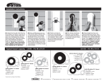
Integrating Sound Level Meter ST-106 CLASS 1 User’s Manual HB2ST1060000 Contents: 1. SAFETY PRECAUTIONS ......................................................................................................... 3 1.1. Preliminary Description ..................................................................................................... 3 1.2. Note ................................................................................................................................... 3 2. PREPARATION FOR USE ....................................................................................................... 4 2.1. Initial .................................................................................................................................. 4 2.2. Supply Voltage .................................................................................................................. 4 2.3. Calibration ......................................................................................................................... 4 2.4. Storage .............................................................................................................................. 4 3. ST-106 INSTRUMENT INSTRUCTIONS .................................................................................. 5 3.1. Instrument Description ...................................................................................................... 5 3.1.1. Controls Description ................................................................................................................... 5 3.3.1. 3.3.2. 3.3.3. 3.3.4. 3.3.5. 3.3.6. 3.3.7. Sound Pressure Level Lxyp/ Equivalent Continuous Level Lxeq1s Measurement (Page0) ...... 8 Integrating Measurement (Page1) .............................................................................................. 9 Big Font Measurement Manual Optional Item (Page2) ............................................................ 10 Explanation ............................................................................................................................... 11 Input Interface ........................................................................................................................... 12 AC Output Interface .................................................................................................................. 12 DC Output Interface .................................................................................................................. 12 3.4.1. 3.4.2. 3.4.3. 3.4.4. Operation Main Menu ............................................................................................................... 13 Acoustical Calibration With ST-110 .......................................................................................... 14 Direct Input Sensitivity Value .................................................................................................... 15 View Calibration Record ........................................................................................................... 16 6.1.1. 6.1.2. Standard: .................................................................................................................................. 22 General Data ............................................................................................................................ 22 6.2.1. 6.2.2. Environmental Conditions......................................................................................................... 22 EMC .......................................................................................................................................... 23 6.3.1. 6.3.2. Standard Accessories ............................................................................................................... 23 Optional Accessories ................................................................................................................ 23 3.2. 3.3. Operation Instructions ....................................................................................................... 6 Measurement Mode (Measure) Instruction ....................................................................... 7 3.4. Acoustic Calibration Mode (Calibration) Instructions....................................................... 13 3.5. The Microphone Lengthens The Test ............................................................................. 16 ST-110 SOUND LEVEL CALIBRATOR’S DESCRIPTION (OPTIONAL) ................................ 17 4.1. Introduction...................................................................................................................... 17 4.2. Equivalent Free-Field ...................................................................................................... 17 4.3. Specifications - Sound Level Calibrator .......................................................................... 18 4.4. Operating Instructions ..................................................................................................... 18 4.5. Calibration And Adjustment ............................................................................................. 19 4.6. Battery Replacement ....................................................................................................... 19 5. MAINTENANCE ...................................................................................................................... 20 5.1. General Information......................................................................................................... 20 5.2. Battery Replacement ....................................................................................................... 20 5.3. Cleaning .......................................................................................................................... 20 5.4. End Of Life ...................................................................................................................... 20 6. TECHNICAL SPECIFICATIONS ............................................................................................. 21 6.1. Feature ............................................................................................................................ 21 4. 7. 6.2. Environment .................................................................................................................... 22 6.3. Accessories ..................................................................................................................... 23 SERVICE ................................................................................................................................ 24 7.1. Warranty Conditions ........................................................................................................ 24 7.2. Service ............................................................................................................................ 24 EN - 1 EN - 2 1. SAFETY PRECAUTIONS When taking measurements: z Avoid doing measurements in humid or wet places - make sure that humidity is within the limits indicated in section “environmental conditions”. z Avoid doing measurements in presence of explosive gas, combustible gas, steam or excessive dust. The following symbols are used: Caution: refer to the user’s manual. An incorrect use may damage the tester or its components The instrument conforms to the CE standard 1.1. Preliminary Description ST-106 is a high performance conforms to international IEC61672 Class 1 Integrating Sound Level Meter. It may also survey: Lxyi, Lxyp, Lxeq, Lxmax, Lxmin, LAE, Lcpeak, Lzpeak, three kind of at the same time frequency weighting (A, C, Z) and three kind of at the same time weighting (F, S, I) may simultaneously survey many kinds of appraisal target, the dynamic range is bigger than 110dB, it does not need to select the measuring range when doing measurements, the operation is simple. Applications: Evaluation of environmental noise, Measurements of noise at workplaces, Assessment of product noise. 1.2. Note CAUTION Does not observe the warning and/or operation instruction, it’s possible to damage the instrument either its components or the operator z z z Do not operate the instrument at temperature and humidity environment beyond to reference conditions of chapter 6.2.1. Keep the microphone dry and avoid severe vibration. Wind blowing across the microphone would bring additional extraneous noise. Once using the instrument in the presence of wind, it must mount the windscreen to prevent the undesirable signals. (Refer to Fig. 3) EN - 3 2. PREPARATION FOR USE 2.1. Initial The instrument has been checked mechanically and electrically prior to shipment. Take care to ensure the instrument reaches you undamaged. However, it is wise to carry out a rapid check in order to detect any possible damage that may cause during transport. If its damage, claims to the dealer immediately. Check the packaging content according to packing list reported in 6.3.1chapter .In case of discrepancies, contact the dealer immediately. In the event of re-shipment of the instrument please follow the instructions reported in chapter. 2.2. Supply Voltage The instrument is powered by batteries (refer to chapter 6.1.2 for details on model, no. and battery life). When batteries are low, a low battery indication is displayed. To replace/insert batteries as the instructions indicated in chapter 5.2. The instrument can also be powered by the external power supply. The external power supply’s voltage is 4~5V and its maximum output current is 500mA. CAUTION If you don’t use the instrument for a long period, please take the batteries out to prevent eventual acid leakage from damaging the instrument 2.3. Calibration The instrument complies with the technical specifications contained in this manual and such compliance is guaranteed for 1 year. The instrument is maybe need recalibration after one year. 2.4. Storage After a period of storage in extreme environmental conditions exceeding the limits mentioned in paragraph 6.2.1 let the instrument return to normal measuring conditions before using it. EN - 4 3. ST-106 INSTRUMENT INSTRUCTIONS 3.1. Instrument Description 3.1.1. Controls Description 1. Microphone 1A. Preamplifier. 2. 3. : Turns on the power (press a second more) or carries on the reset to the instrument. : Turn off. 4. : Deletes the current measurement result. 5. : Lightens the backlight, automatic shut-off after the indicated time delay. presses again to closes the backlight. 6. LCD display. 7. 8. : Enters to next or choose Page0~Page2 or determine the current input. : Returns to previous menu. 9. : Finished the current measurement. 10. : Starts or pause integral measurement. 11. : The cursor adds 1 in the position parameter, presses down tightly, the parameter adds 1 continuously, when comes to the starting picture, presses this key to change LCD pale. 12. : The cursor reduces 1 in the position parameter, presses down tightly, the parameter reduces 1 continuously, when comes to the starting picture, presses this key to change the LCD depth. 13. : The cursor move to right side, or presses down tightly, cursor continually move to right side. 14. : The cursor move to left side, or presses down tightly, cursor continually move to left side. 15. : Set up backlight auto shut-off time, when LCD in the starting picture, presses this key, the LAMP time will be changed from 5 seconds up to 95 seconds. Fig. 1 EN - 5 3.2. Operation Instructions Pressing power button display for mode. Select more than a second to start the instrument, enters to initial list or key, “Measure” (refer to chapter 3.3) or mode “Calibrate” (refer to chapter 3.4), press key for making measurement or calibration. If it’s mistake in selection, may press the key to return to the initial list display. Presses the z key to set up the backlight (5~95 seconds). LCD contrast setup: The user may press and key to setup LCD contrast, the number from 0~25. Fig. 2 CAUTION Wind blowing across the microphone would bring additional extraneous noise. Once using the instrument in the presence of wind with speed higher than 10m/s, it must mount the windscreen to prevent the undesirable signals. Keep the microphone dry and avoid severe vibration. Fig. 3 EN - 6 3.3. Measurement Mode (Measure) Instruction Fig. 4 EN - 7 When enters the measurement mode according to chapter 3.2 operations, may press down the key to change 3 kind of display pages, sound pressure level Page0, integrating measurement Page1, manual “big font display” measurement mode: Page2, Total: 3 kind of display modes, and may press the key to watch 3 kind of display modes repeatedly as necessary, 3 kind of display modes measurement are operate, simultaneously, including the integrating measurement, when presses down the 3 kind of display pages are in integrating measurement simultaneously. 1. Integrating measurement time setup: "Ts" was the integrating measurement time, "Tm" is the integrating accumulation time. The user may press down the the users push 2. key, key to revise the Ts time. If "Ts" is in “00h00m00s”, to finish it. Integrating measurement start/pause: The user presses down the key to start the integrating measurement, until the "Ts” setup time. In the integrating measurement process may manually press down key to pause it, in the pause condition, press a the it’s necessary. 3.3.1. key erasing the data if Sound Pressure Level Lxyp/ Equivalent Continuous Level Lxeq1s Measurement (Page0) Fig. 5 When chooses Page0 LCD displays A, C, Z three kind of frequency weighting, and F, S, I three kind of time weighting sound pressure level simultaneously. The bottom chart is bargraph, press the or key, the cursor may change LASi, LAIi, LZFi, LZSi, LZIi, LCFi, LCSi, LCIi, LAFi. *** Lxyp and Lxeq1s (refer to chapter 3.3.4) *** EN - 8 3.3.2. Integrating Measurement (Page1) Fig. 6 1. When chooses Page1 to set up integrating measurement time "Ts" firstly: press the key, to set up measuring time, (refer to Fig. 6) , the “Ts” integration time is setup, press key, the integrating measurement can be change from 10 seconds, 1 minute, 5 minutes, 10 minutes, 20 minutes, 30 minutes, 1 hour, 2 hours, 4 hours, 8 hours, 16 hours, 24 hours, manual is the measurement time in “00h00m00s”, when turn off the power it will automatically store the setting value. 2. LCD display Lxeq, LAE, Lcpeak, Lzpeak, Lxmax, Lxmin simultaneously when set up the measurement time "Ts", press the key, the instrument starts the integrating measurement, "RUN" is displayed on the right bottom corner , measurement’s accumulation "Tm" starts to increase, When the measurement time reaches the setup time, the measurement will be stopped. In the operation press, presses key, then measurement is suspended, "PAUSE" is displayed on the right bottom corner, the integrating measurement time is suspended. If presses measurement value will be erased. If press (refer to Fig. 6) 3. Under this mode, may press the or key, the current key, then continues to measurement. key moving the cursor to WEI: presses the or key changing time weighting F, S, I set again. *** Lxeq, LAE, Lcpeak, Lzpeak, Lxmax, Lxmin (refer to chapter 3.3.4) *** EN - 9 3.3.3. Big Font Measurement Manual Optional Item (Page2) Fig. 7 1. This mode provides two kinds of big font values, the user may press or key, the cursor can be changed in "LAFi ", "LCFp", "LAFp". The cursor is in "LAFi" icon, presses or key to be changes the analog bargraph measuring mode. When cursor on the "LCFp" or "LAFp" icon, pressing the measurement mode. or key to change 2. When set up LZFp 、 LZSp 、 LZIp 、 LCFp 、 LCFp 、 LCIp 、 LAFp 、 LASp 、 LAIp 、 LAeq1s、LCeq1s、LZeq1s,measurement value will be displayed directly. 3. When set up LAeq,T、LCeq,T、LZeq,T、LZFmax、LZFmin、LZSmax、LZSmin、 LZImax 、 LZImin 、 LCFmax 、 LCFmin 、 LCSmax 、 LCSmin 、 LCImax 、 LCImin 、 LAFmax、LAFmin、LASmax、LASmin、LAImax、LAImin、LAE、LCpeak、Lzpeakg For the integrating measurement function, it must start the integrating measurement function to provide the display value (presses the previous value, it will display —﹒— 。 EN - 10 key).If the memory does not save 3.3.4. Explanation 1. Measurement Parameters: Default Frequency Time Explanation Parameter Screen Weighting Weighting parameter Lxyp LAFp A,C,Z F,S,I Sound pressure level (SPL) (see *2) 1 second X frequency weighting Equivalent Lxeq1s LAeq1s A,C,Z continuous level. (see *1) T second X frequency weighting Equivalent Lxeq,T LAeq,T A,C,Z continuous level. (see *1) Lxyi LAFi A,C,Z Randomly sampled instantaneous value of F,S,I (Lyons) RMS level.(see *2) Lxeq LAeq A,C,Z Equivalent continuous level for the duration of the measurement.(see *1) Lxmax LAFmax A,C,Z F,S,I Max. Lxyp value detected within the elapsed time.(see *2) Lxmin LAFmin A,C,Z F,S,I Min. Lxyp value detected within the elapsed time.(see *2) LAE LAE A Frequency weighted sound exposure level for the duration of the measurement. Lcpeak Lcpeak C Instantaneous C peak level. Lzpeak Lzpeak Z Instantaneous Z peak level. *1︰X is A,C,Z frequency weighting. *2︰X is A,C,Z frequency weighting.,Y is F,S,I time weighting. 2. A, C, Z Weighting Instruction: A: The A weighting curve is based on 40 Phon Fletcher-Munson Equal Loudness Contour, Noise assessment in human, suggest to use the A weighting. C: The C weighting in essentially is approximate smooth. With labor safety concern, suggest using the C weighting. Z: The Z weighting for the electric instrument interior not the linear signal which processes after the filter, suits in wants to output AC or the DC signal does other research to use. The Z weighting is a linear signal which is not processed through the filter. It’s suitable to output AC or DC signal for research. 3. Sound Level Meter Class Description: z z z z Class 0: use in the laboratory reference standard. Cass 1: laboratory or field use. Class 2: laboratory or field use. Class 3: general field use. EN - 11 3.3.5. Input Interface The front is X9-6z, the signal input receptacle. The pin definition and function are shown in Fig. 8: Pin 1 Pin 2 Pin 3 Pin 4 Pin 5 Pin 6 Power supply Null Signal input Null Signal ground Null Fig. 8 3.3.6. AC Output Interface The AC signal output is corresponding to the frequency weighting (Refer to Fig. 9) Output voltage: Output impedance: Load impedance: Load capacitance: 1Pa sound pressure=15mV. approx. 1kΩ more than 100kΩ less than 100 pF 3.3.7. DC Output Interface The DC signal’s output is corresponding to the frequency weighting. (Refer to Fig. 9) Output voltage: Approx. 20mV/dB DC output is provided by the second PIN of RJ45, the pins definition is shown in Fig. 9, DC OUT: the output is same as bargraph. Output pin definition is as following: Pin number position from right to left (1~8). Pin 1 is Ground Pin 2 is Signal Pin 3~8 null. Signal Ground Fig. 9 output receptacle Fig. 10 3.5mm output plug EN - 12 3.4. Acoustic Calibration Mode (Calibration) Instructions 3.4.1. Operation Main Menu On the main menu,move the cursor to "CALIBRATE" icon and press “ display: key, it will Fig. 11 Chart Fig. 11 for entering the adjustment mode main menu; please find the following items in order: z Item 1.MIC Serial: It is the microphone’s serial number, which is set by factory and cannot be modified by user. z Item 2.Free Field Correction: The item 2 is the microphone’s free field correction, which is set according to the microphone’s type. The ST-106 Sound Level Meter uses 1/2" free field microphone, its correction between sound pressure field and free field is 0.15 dB at the frequency of 1 kHz. z Item 3.Mic. Sensitivity: The item 3 is microphone’s sensitivity level, which is the sensitivity output level of preamplifier when preamplifier is set on the microphone. The microphone should be calibrated to get a new sensitivity level when the preamplifier is replaced, as the amplifier has a certain input capacitance and gain. z Item 4.Normal SPL: The Item 4 is calibrator’s sound pressure level, which is the actual sound pressure level after sound level calibrator is checked. LpC: when the analyzer is calibrated by C weight. LpX: indicates the microphone’s current sensitivity level Up-SPL、Under-SPL: Measuring upper and lower limit. The last line is the menu, "LIST" button is used to view the calibration records, "Cal" button is used to start the sound calibration, "App" button is used to store the calibration result and use the new sensitivity level for the measurement later, "Mod" button allows user to adjust the free field correction, the microphone sensitivity level and the calibration sound pressure level. EN - 13 3.4.2. Acoustical Calibration With ST-110 Fig. 12 1. For the first acoustical calibration, set "calibrator sound pressure level" according to the calibration certificate of ST-110 Sound Level Calibrator. In general, the sound pressure level of the sound level calibrator is 94.0 dB, when the measured sound pressure level is not 94.0 dB, please calibrate it by the actual result, for example, if 94.2 dB, please modify the item 4. (Normal SPL) value to 94.2dB。Move cursor to "Mod" icon, and press SPL) ". button,and presses the Each presses or Continuously presses or key move cursor to the "Item 4 (Normal , the value increases or reduces 0.01dB. or the value increases or reduces 1dB. Move cursor to "App" icon and press level is stored. key, then microphone’s new sensitivity CAUTION The above step is carried only when the indicated calibrator’s sound pressure is different from that of the working sound level calibrator. 2. Place the ST-110 Sound Level Calibrator on to the microphone, turn the power on and wait for a few seconds. Move display’s cursor on “ Cal” icon and press key, the instrument will calibrate automatically. During the calibration, the display’s upper left side shows a counting number started from 0 when counted to 9 namely the calibration is completed. “LpC” indicates the sound pressure level, which is around the result that subtracts the free correction from the sound pressure level of calibrator. “LpX” indicates the sensitivity level after calibration. EN - 14 key, the microphone’s new sensitivity 3. Move the cursor to “ App” icon and press level is stored. After the storage, Up-SPL and Under-SPL will be renewed and displayed the upper and lower limits of the scope after the adjustment. If the difference is more than 3 dB between the new and stored sensitivity-values, the instrument will not store the value, and the LCD display prompts “ The Difference Between These Two Sensitivity Is Too Large! Please affirm the calibration is correct. “. Please go through the above steps again and confirm the microphone is wellfunctioning. Fig. 13 3.4.3. Direct Input Sensitivity Value If the user does not has the calibrator,please input the Sound Level Meter’s sensitivity value directly. Move the cursor to "Mod" icon, press project 3.Mic. Sensitivity: Each presses or Continuously presses key, then move the cursor to the , the key value increases or reduces 0.01dB or the key value increases or reduces 1dB. Move cursor to "App" button, press stored. key, and then microphone’s new sensitivity level is EN - 15 3.4.4. View Calibration Record Fig. 14 key to The user can read the calibration record, move cursor to "LIST" icon and press enter the calibration’s record data frame, If the data is more than 9 records, you can press 、 to go to the previous or next page. The instrument will store the record each time; it can save up to 128 records, if save more than 128 records, the instrument will erase the whole 128 records and only keep the latest one. Press “ function. ” key to escape this 3.5. The Microphone Lengthens The Test In order to avoid the measurement deviation caused by the reflection effect and operation problem, use the cable to extend the microphone for measuring. (Refer to chapter 6.3.2). 1. Press button to turn the power off. 2. Turn the preamplifier and microphone counterclockwise to be separated from the main body. (Refer to Fig. 15). 3. Connect the extension cable to the microphone and main body. (Refer to Fig. 16). Fig. 16 Fig. 15 EN - 16 4. ST-110 SOUND LEVEL CALIBRATOR’S DESCRIPTION (OPTIONAL) 4.1. Introduction The ST-110, Sound Level Calibrator, is used for the calibration of the pressure sensitivity of the microphone and sound level measuring equipment. The design of ST-110 is based on a feedback arrangement to ensure a high stable sound pressure level. The performance is very stable; it does not required for the revision to the microphone equivalent volume. ST-110 conforms to the standard of IEC60942 (2003) Class 1. (Refer to Fig. 17) 4.2. Equivalent Free-Field Usually we use the free-field microphone more than others. For example, when use the ST-100 to calibrate the sound level meter and other environmental noise measuring equipments need to revise the pressure-field to the equivalent free-field. The corrected value is the difference between the pressure-field response and free-field response when at 1000Hz. The value for the 23.77mm (1 inch) microphone is –0.4dB, and for the 12.7mm (1/2 inch) microphone is –0.2dB. Also the equivalent free-field for the 23.77mm (1 inch) microphone is 93.6dB, and for the 12.7mm (1/2 inch) microphone is 93.8dB. Fig. 17 EN - 17 4.3. Specifications - Sound Level Calibrator Standard: IEC 60942(2003) and ANSI S1.40 (1984) Sound Pressure Levels:94 and 114dB(reference of 2x10⁻⁵Pa)。 Accuracy: 94 ± 0.3dB and 114 ± 0.5dB. Frequency:1000Hz ± 1%. Distortion:≤ 1 %. Battery:9V 006P or IEC6F22 or NEDA 1604. Dimension::φ53x117(mm). Weight:about 250g(included 1/2" adaptor and 9V battery). Stable Times:3s。 Operating Temperature:-10℃ ~ 50℃ (14℉ ~ 122 ℉). Storage Temperature: -25℃ ~ 0℃ (-13℉ ~ 158 ℉). Humidity:<90%. Atmospheric Pressure:65KPa~100KPa Accessories:1/2" (12.7mm) adaptor、user’s manual x1、calibration certificate x1 4.4. Operating Instructions 1. Turn the power on, the LED will be lightened and the meter emits a sound. 2. Insert the 1/2 inches microphone to the hole of ST110 Sound Calibrator until you hear a "click" sound. (refer to Fig. 18) 3. Select the sound level of 94dB or 114dB. Press “ON” it supplies 94dB. Press ON and +20dB simultaneously, it supplies 114dB. 4. Read the value on the sound level meter’s display and perform the calibration 5. Extract the microphone. 6. The calibrator will be power-off automatically after 1 minute. Fig. 18 EN - 18 4.5. Calibration And Adjustment If calibration out of specification, you can calibrate and adjustment it: 1. Unscrew completely the metal silver battery cover. 2. Uses a small screw driver trimming interior variable resistor until attain a designated standard the accurate 94dB normal value. CAUTION When verification should use the pressure field response laboratory scale microphone as well as the precision measurement amplifier carries on the measuring. Does not need to 114.0dB to carry on the adjustment. 4.6. Battery Replacement CAUTION The battery voltage should maintain more than 5.5V,when use, after lets loose the pressed key, the sound presses the adjuster to be supposed to maintain works a minute .If only can work for several seconds or does not work, then the battery lower, should replace the battery 1. Unscrew completely the metal silver battery cover. 2. Remove the battery. 3. Replace the battery with a new one of the same type. Description Of Calibrator 1. Metal silver battery cover. 2. Power ON red LED. 3. Power ON and _20dB button. 4. 1/2" adapter. 5. 0.936” internal cavity of calibrator. Fig. 19 EN - 19 5. MAINTENANCE 5.1. General Information This is a precision instrument. To guarantee its performances be sure to use it or keep it stored on suitable environmental conditions. Do not expose it to high temperatures or humidity or direct sunlight. Be sure to turn it off after use. If you expect not to use the instrument for a long period remove batteries to avoid leakages of battery liquid which could damage the its inner components. 5.2. Battery Replacement The low battery “ ” indication (refer to chapter 6.1.2) is displayed, the batteries are to be replaced. Turn off the instrument. Remove the battery cover. Remove all the batteries from the battery holder. Insert four new batteries of the same type (refer to chapter 6.1.2) respecting the polarity signs. Install the battery cover. Please depend on the local laws and regulations to process the waste battery。 Fig. 20 : Opening and closing of battery cover 5.3. Cleaning z To clean the instruments use a soft dry cloth. Never use a wet cloth, solvents or water. 5.4. End Of Life Caution: this symbol indicates that equipment and its accessories shall be subject to a separate collection and correct disposal EN - 20 6. TECHNICAL SPECIFICATIONS 6.1. Feature Environmental conditions: temperature 23℃ ± 5℃, relative humidity < 80%. Specifications: Display Display Refresh Rate LCD with Back Light (Green Yellow Light)(240X160 dots) Real time clock, Year, Month, Minute 1 Hz for value; 10 Hz for graph Major Applicable Standards IEC 61672-1:2002 Class1 Other Standards Microphone IEC60651:1979 TYPE 1 IEC60804:2000 TYPE 1 1/2” pre-polarized condenser microphone build in preamplifier: 40 mV/Pa, frequency range: 10 Hz~16 kHz, heat noise: <20 dB(A) Measurement Items Lxyi,Lxyp,Lxeq,Lxmax,Lxmin,LAE,Lcpeak,Lzpeak Measurement Range 30dB to 130dB (A) 35dB to 130dB (C) 40dB to 130dB (Z) Dynamic Range Integrate Time Setup >110 dB randomly,10s,1m,5m,10m,20m,30m,1h,2h,4h,8h,16h,24h 70~133 dB Maximum Peak C Weighting Sound Level Measurement Time Weighting Fast, Slow, Impulse, Peak Frequency Weighting A/C/Z 10Hz~16KHz Frequency Range Sampling Rate 20.8µs (48KHz) Analog Output AC 20mV/dB Starting Time <10 Second Battery Life 8 hours (LR6:4 Alkaline batteries) AC Adapter Input:100V~240V ACV,Output:5V DCV Dimensions 285(L) x 90(W) x 39(H) mm Weight 500g ( including Batteries) EN - 21 6.1.1. Standard: The instrument complies with IEC 61672 (2002) class 1 and CNS 7129 Class 1. IEC60651:1979 TYPE 1, IEC60804:1985 TYPE 1, ANSI S1.4:1983 Type1. 6.1.2. General Data Mechanical characteristics Dimension Weights (including batteries) 285(L) x 90(W) x 39(H) mm approximate 500g Power supply: Battery type 4 batteries 1.5 V – LR6 – AA – AM3 – MN 1500 Indication of low batteries when batteries voltage is too low LCD display “ ” icon and LOW BATTERY (Note: If you don’t use the analyzer for a long time, please take the batteries out). Battery life: Approximate 8 hours AC to DC Adapter: z Outside meets AC to transform DC the 5V power source supplies (attention power source polarity) :( refer to Fig. 21), Current>500mA。 z Plug:The center connects PIN is a positive electrode,outside metal is negative electrode. z Outside diameter 3.5φ、inside diameter 1.1φ(Refer to Fig. 22). Fig. 21 Fig. 22 Display 240x160 dot LCM with LED Backlight. 6.2. Environment 6.2.1. Environmental Conditions z For inside use, max height: z Reference temperature: z Operation temperature: z Operation humidity: z Storage temperature z Storage humidity 2000m 23° ± 5℃ 5 ~ 40 ℃ <80% RH -10 ~ 60 ℃ <70% EN - 22 6.2.2. EMC This instrument was designed in accordance with EMC Standards in force and its compatibility has been tested in accordance with EN61326-1 (2006). 6.3. Accessories 6.3.1. Standard Accessories z Meter: ST-106. z User’s manual. z Switching power supply: 100V ~ 240V AC to DC 5V/1A. z Carrying case. z 4 batteries 1.5 V – LR6 – AA – AM3 – MN 1500. z 60mm diameter windscreen. 6.3.2. Optional Accessories z 5M microphone cable. z 10M long microphone cable z 20M long microphone cable z ST-110 sound level calibrator. EN - 23 7. SERVICE 7.1. Warranty Conditions This instrument is guaranteed for one year against material or production defects, in accordance with our general sales conditions. During the warranty period the manufacturer reserves the right to decide either to repair or replace the product. Should you need for any reason to return back the instrument for repair or replacement take prior agreements with the local distributor from whom you bought it. Do not forget to enclose a report describing the reasons for returning (detected fault). Use only original packaging. Any damage occurred in transit due to non-original packaging will be charged anyhow to the customer. The warranty doesn’t apply to: Accessories and batteries (not covered by warranty). Repairs made necessary by improper use (including adaptation to particular applications not foreseen in the instructions manual) or improper combination with incompatible accessories or equipment. Repairs made necessary by improper shipping material causing damages in transit. Repairs made necessary by previous attempts for repair carried out by non-skilled or unauthorized personnel. Instruments for whatever reason modified by the customer himself without explicit authorization of our Technical Dept. The contents of this manual may not be reproduced in any form whatsoever without the manufacturer’s authorization. Our products are patented. The logotypes are registered. We reserve the right to modify characteristics and prices as part of technological developments which might require them. 7.2. Service Shouldn’t the instrument work properly, before contacting your distributor make sure that batteries are correctly installed and working, check the test leads and replace them if necessary. EN - 24