1
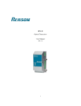
RT411
Time Signal Distributor
User Manual
(Rev 1.1)
1
Contents
Preface
3
About the Document
3
Contact
4
Acronyms and Abbreviations
5
1
Getting Started
6
1.1
Description . . . . . . . . . . . . . . . . . . . . . . . . . . . . . . . . . . . . . . . . . . . . .
6
1.2
Unpacking . . . . . . . . . . . . . . . . . . . . . . . . . . . . . . . . . . . . . . . . . . . . . .
6
1.3
External Indications . . . . . . . . . . . . . . . . . . . . . . . . . . . . . . . . . . . . . . . . .
7
2
3
4
Specifications
8
2.1
Electrical Input . . . . . . . . . . . . . . . . . . . . . . . . . . . . . . . . . . . . . . . . . . .
8
2.2
Optical Input . . . . . . . . . . . . . . . . . . . . . . . . . . . . . . . . . . . . . . . . . . . .
8
2.3
Electrical Outputs . . . . . . . . . . . . . . . . . . . . . . . . . . . . . . . . . . . . . . . . . .
8
2.4
Optical Outputs . . . . . . . . . . . . . . . . . . . . . . . . . . . . . . . . . . . . . . . . . . .
9
2.5
Power Supply . . . . . . . . . . . . . . . . . . . . . . . . . . . . . . . . . . . . . . . . . . . .
9
2.6
Environment . . . . . . . . . . . . . . . . . . . . . . . . . . . . . . . . . . . . . . . . . . . . .
9
2.7
Weight and Dimensions . . . . . . . . . . . . . . . . . . . . . . . . . . . . . . . . . . . . . . . 10
Description
11
3.1
Features . . . . . . . . . . . . . . . . . . . . . . . . . . . . . . . . . . . . . . . . . . . . . . . 11
3.2
Front Panel Components . . . . . . . . . . . . . . . . . . . . . . . . . . . . . . . . . . . . . . 11
3.3
Posterior Panel Components . . . . . . . . . . . . . . . . . . . . . . . . . . . . . . . . . . . . 12
Installation
13
4.1
Mounting . . . . . . . . . . . . . . . . . . . . . . . . . . . . . . . . . . . . . . . . . . . . . . 13
4.2
Environment . . . . . . . . . . . . . . . . . . . . . . . . . . . . . . . . . . . . . . . . . . . . . 13
4.3
Power Supply . . . . . . . . . . . . . . . . . . . . . . . . . . . . . . . . . . . . . . . . . . . . 13
4.4
4.3.1
AC Power Connection . . . . . . . . . . . . . . . . . . . . . . . . . . . . . . . . . . . 14
4.3.2
DC Power connection . . . . . . . . . . . . . . . . . . . . . . . . . . . . . . . . . . . 15
Powering Up . . . . . . . . . . . . . . . . . . . . . . . . . . . . . . . . . . . . . . . . . . . . 15
2
4.5
5
Time Reference Inputs . . . . . . . . . . . . . . . . . . . . . . . . . . . . . . . . . . . . . . . 15
4.5.1
Selection of the Time Reference Input . . . . . . . . . . . . . . . . . . . . . . . . . . . 16
4.5.2
Connection Diagrams of the Synchronism Inputs . . . . . . . . . . . . . . . . . . . . . 17
4.6
Optical Outputs . . . . . . . . . . . . . . . . . . . . . . . . . . . . . . . . . . . . . . . . . . . 18
4.7
Electrical Outputs . . . . . . . . . . . . . . . . . . . . . . . . . . . . . . . . . . . . . . . . . . 18
Maintenance
5.1
19
Troubleshooting . . . . . . . . . . . . . . . . . . . . . . . . . . . . . . . . . . . . . . . . . . . 19
5.1.1
P OWER Indicator does not light up . . . . . . . . . . . . . . . . . . . . . . . . . . . . . 19
5.1.2
ACT Indicator does not light up . . . . . . . . . . . . . . . . . . . . . . . . . . . . . . 19
5.2
Cleaning Instructions . . . . . . . . . . . . . . . . . . . . . . . . . . . . . . . . . . . . . . . . 19
5.3
Returning a Unit . . . . . . . . . . . . . . . . . . . . . . . . . . . . . . . . . . . . . . . . . . 19
3
4
Reason Tecnologia S.A.
Preface
c 2013 2011 Reason Tecnologia S.A., all rights reserved.
Products developed by Reason are continuously improved. The information this document contains reflects this
improvement, and for this reason it is subject to change without notice. Please make sure that this is latest
version of this document before proceeding. All specifications are subject to changes without prior notice.
Certification to the ISO 9001:2008 quality standard is an
example of this commitment. We encourage and appreciate any feedback and will use it to improve our products
and services.
About the Document
This manual is intended to technically qualified personnel who has been trained or is knowledgeable in instrumentation and engineering fields.
This user manual is part of the scope of delivery and provides basic information for installation, configuration,
operation and maintenance of the equipment here described. In case additional information is needed, please
contact Reason at the addresses provided at the beginning of this document.
Document Id: rt411-manual-en
Revision: 1.1
According to:
Hardware Version 01
RT411 - User Manual
[rt411-manual-en rev 1.1]
Contact
Reason Tecnologia S.A.
Rua Delminda Silveira, 855
88025-500 Florian´opolis, SC
Brasil
Fone: (48) 2108-0300
Fax: (48) 2108-0310
http://www.reason.com.br
Reason International, Inc.
5900 Southwest Parkway, Suite 210
Austin, TX 78735
USA
Phone: (512) 615-0490
Fax: (512) 615-0491
http://www.reason-international.com
RT Measurement Technologies GmbH
Rudower Chaussee 29
12489 Berlin
Germany
Phone: +49 (0)30 57 70 63 32
http://www.rtgmbh.eu
6
Reason Tecnologia S.A.
Acronyms and Abbreviations
AC - Alternating Current;
BNC - Bayonet Neil Concelman connector;
DC - Direct Current;
DCF77 - DeutschlandLORAN-C Time synchronism protocol (Long Range Navigation - C) Frankfurt 77 (77,5 kHz);
IEC - International Electrotechnical Commission;
IED - Intelligent Electronic Devices;
IRIG-B - Time synchronism protocol Inter Range Instrumentation Group (Rate Designation B);
PPS - Pulse-per-second;
PPX - Pulse-per-X s;
RT - Time recorder (Time synchronism equipment of Reason);
ST - Bayonet-lock connector;
RT411 - User Manual
[rt411-manual-en rev 1.1]
7
Reason Tecnologia S.A.
1
1.1
Getting Started
Description
RT431 - Time Signal Distributor is an electrical signal multiplier. It multiplies IRIG-B demodulated, PPS or
any signal with a voltage between 0 and 5 V d.c., to frequencies up to 5 MHz, through electrical and optical
outputs, allowing the synchronization of IEDs. The equipment ensures time accuracy based on the accuracy of
the time reference source that is being used in the input.
The equipment has up to 10 electrical outputs with a 150 mA individual supply capacity and up to 10 optical
outputs for multimode fiber and ST connector.
It also has frontal indicators for monitoring the received synchronism signal and voltage of the primary supply.
1.2
Unpacking
Unpack the equipment carefully and make sure all the accessories and cables are put aside so they will not
be lost. Check the contents against the packing list that goes with the product. If any of the content listed is
missing, please contact Reason (see contact information at the beginning of this manual).
Examine the equipment for any shipping damage. If the equipment is damaged or fails to operate, notify the
shipping company without delay. Only the consignee (the person or company receiving the equipment) can file
a claim against the carrier for shipping damage.
We recommend you keep the original packing materials for eventual future transport.
RT411 - User Manual
[rt411-manual-en rev 1.1]
8
Reason Tecnologia S.A.
1.3
External Indications
The specifications of the connections are shown on an external label above the equipment. The serial number
and part number are shown on a label fixed on the side of the equipment, as shown in Figure 1.
Figure 1: Location of Serial number, Part Numberand specifications of the connections
RT411 - User Manual
[rt411-manual-en rev 1.1]
Reason Tecnologia S.A.
2
2.1
9
Specifications
Electrical Input
Table 2.1: Electrical Input Specifications
Signals
IRIG-B00, PPX, DCF77, and signals with
a voltage between 0 and 5 V d.c.
Isolation Voltage
2500 V
High Level 1
Between 4.5 V d.c. and 5 V d.c.
Low Level 2
< 0.2 V d.c.
Impedance
> 18 Ω
2.2
1
Level above which the equipment recognizes input as activated;
2
Level below which the equipment recognizes input as disabled.
Optical Input
Table 2.2: Optical Input Specifications
Signals
IRIG-B00, PPX, DCF77, and signals with
a frequency up to 5 MHz
Connector
ST
Wave Length
820 nm
Wave Length
multimode 50 / 125 µm, 62.5 / 125 µm,
100 / 140 µm or 200 µm HCS
Sensibility
−24 dBm
2.3
Electrical Outputs
Table 2.3: Electrical Outputs Specifications
Signals
IRIG-B00, PPX, DCF77, and signals with
a voltage between 0 and 5 V d.c.
Connectors (10)
8 Screw
2 BNC
Current
150 mA
High Level 1
Between 4.5 V d.c. and 5 V d.c.
Low Level 2
< 0.2 V d.c.
Impedance
> 18 Ω
1
Level above which the equipment recognizes output as activated;
2
Level below which the equipment recognizes output as disabled.
RT411 - User Manual
[rt411-manual-en rev 1.1]
Reason Tecnologia S.A.
2.4
10
Optical Outputs
Table 2.4: Optical Outputs Specifications
Signals
IRIG-B00, PPX, DCF77, and signals with
a frequency up to 5 MHz
Connector
ST
Wave Length
820 nm
Fiber Type
multimode 50 / 125 µm, 62.5 / 125 µm,
100 / 140 µm or 200 µm HCS
Transmission Power
−17.8 dBm (50 / 125 µm)
−14.0 dBm (62.5 / 125 µm)
−8.5 dBm (100 / 140 µm)
−5.7 dBm (200 µm HCS)
We recommend the use of optical-fiber cables with a maximum length of 2 Km.
2.5
Power Supply
Table 2.5: Power Supply Specifications
Operating rated voltage
100–250 V d.c., 110–240 V a.c.
Operating voltage range
80–275 V d.c., 88–264 V a.c.
Frequency
50/60 Hz ±3 Hz
Consumption
15 W
2.6
Environment
Table 2.6: Environment Specifications
Recommended temperature range
+5 . . . +55 ◦ C (+41 . . . +131 ◦ F )
Tested temperature range
−25 . . . +70 ◦ C (+13 . . . +158 ◦ F )
Enclosure protection
IP40
Relative humidity
5 . . . 95%, noncondensing
RT411 - User Manual
[rt411-manual-en rev 1.1]
11
Reason Tecnologia S.A.
2.7
Weight and Dimensions
Table 2.7: Weight and Dimensions Specifications
Height
1U
Width
430 mm (16.9 in)
Depth
180 mm (7.1 in)
Weight
2.7 Kg (5.9 lbs)
RT411 dimensions are shown in Figure 2.
Figure 2: RT411 Dimensions
RT411 - User Manual
[rt411-manual-en rev 1.1]
12
Reason Tecnologia S.A.
3
3.1
Description
Features
• 10 Optical outputs with ST and multimode fiber connectors;
• 10 Electrical outputs with an individual supply capacity up to 150 mA;
• Delay in the electrical and optical outputs lower than 100 ns (1 sigma);
• Insulated electrical outputs;
• Accepts IRIG-B00X, PPS, PPM, DCF77 and any signal with voltage between 0 and 5 V d.c. (frequency
lower than 5 MHz);
• Outputs allow the use of electrical cables with a length up to 100 m for IRIG-B signal;
• Frontal indicators for monitoring the received synchronism signal and voltage of the primary supply.
3.2
Front Panel Components
Figure 3 shows the front panel of the equipment.
Figure 3: RT411 Front View
Front panel indicators:
The ACT indicator reflects the time signal applied in the input, blinking according to the frequency
of the signal.
The P OWER indicator lights up as soon as a primary power supply is connected to the equipment.
When the power supply is disconnected from the equipment, the indicator turns off.
RT411 - User Manual
[rt411-manual-en rev 1.1]
13
Reason Tecnologia S.A.
3.3
Posterior Panel Components
Figure 4 shows all components of the posterior panel of the equipment.
Figure 4: RT411 Posterior View
Posterior panel components:
A AC or DC input;
B 10 optical outputs for synchronism;
C 8 electrical outputs for synchronism with screw connector;
D 2 electrical outputs with BNC connector;
E Jumper to select the type of input signal for time reference;
F Electrical Input for time reference;
G Optical Input for time reference.
RT411 - User Manual
[rt411-manual-en rev 1.1]
14
Reason Tecnologia S.A.
4
4.1
Installation
Mounting
RT411 has been designed to be mounted in a standard 19-inch rack using four M6x15 screws to affix. Allow
adequate clearance for all connections.
In particular, the optical fiber cables should be installed respecting a minimum bend radius of 30 mm.
For more information about dimensions of the equipment, see Chapter 2.
4.2
Environment
Temperature and relative humidity should not exceed the limits stated in Chapter 2. We recommend providing
appropriate heating or cooling measures to ensure that these limits are respected at all times.
4.3
Power Supply
The equipment can be powered from DC or AC power within the limits specified in Chapter 2.
All power connections should use insulated flameproof flexible cable (BWF type) with a 1.5 mm2 cross section,
70◦ C thermal class, and 750 V insulation voltage.
To reduce the risk of electrical shock, pre-insulated tubular pin terminals should be used in the ends of power
connections.
Figure 5: Pre-insulated tubular pin terminals
The pin terminals should be completely inserted into the connectors supplied with the equipment, so that no
metallic parts are exposed. Refer to the figure below to insert it correctly.
A 1.5 mm2 ground lead shall be connected to the terminal marked with the protective earth symbol for safety.
For optimal electromagnetic compatibility, ground the equipment by using a 10 mm wide grounding strap to
connect the frame of the equipment to a good ground point on the mounting rack.
RT411 - User Manual
[rt411-manual-en rev 1.1]
15
Reason Tecnologia S.A.
Figure 6: Supply connector assembly
4.3.1
AC Power Connection
Phase (F) should be applied to terminal 1 and neutral to terminal 2, as shown in Figure 7.
Figure 7: AC power connection
The installation of an external 10 A, category C, unipolar circuit breaker near the equipment is recommended.
The circuit breaker should have an interruption capacity of at least 25 kA and comply with IEC 60947-2 standard.
RT411 - User Manual
[rt411-manual-en rev 1.1]
16
Reason Tecnologia S.A.
4.3.2
DC Power connection
Positive (+) should be applied to terminal 1 and negative (−) to terminal, as shown in Figure 8.
Figure 8: Alimentac¸a˜ o em corrente cont´ınua
The installation of an external 10 A, category C, unipolar circuit breaker near the equipment is recommended.
The circuit breaker should have an interruption capacity of at least 25 kA and comply with IEC 60947-2 standard.
4.4
Powering Up
1. Connect the power supply (including the ground lead) to the appropriate terminals. After connecting the
power supply, the P OWER indicator will light up.
2. If the time signal is already connected to the electrical or optical synchronism input, the ACT indicator
will start blinking according to the frequency of the time signal.
3. In case the equipment does not behave in a way here described, carefully check all power and signal
connections.
4. To turn off the equipment, disconnect the power supply. All front panel indicators will turn off.
4.5
Time Reference Inputs
RT411 has an optical and electrical input for time reference, as shown in Figure 9. The optical and electrical
synchronism inputs accept IRIG-B00X, PPX, DCF77, signals with a voltage between 0 and 5 V d.c., and
frequency up to 5 MHz.
RT411 - User Manual
[rt411-manual-en rev 1.1]
17
Reason Tecnologia S.A.
Figure 9: Electrical and Optical Inputs of time synchronism
To synchronize the equipment using optical fiber, adequate optical fiber should be used, respecting a minimum
bend radius of 30 mm, according to Chapter 2.
To synchronize the equipment using the electrical input, it is recommended the use of twisted pair.
For distances over 3 m, the use of an optical fiber cable is recommended to minimize the effects related to EMC.
The length of the optical fiber cables should not exceed 2 km.
4.5.1
Selection of the Time Reference Input
An electrical jumper allows selecting the input to be used as time reference. Making the connection in the
I NPUT S ELECTION connector, as shown in Figure 10, the electrical time reference port is enabled. In case the
jumper is disconnected, the equipment operates using the optical time reference port.
Figure 10: to select the time reference input (if connected, enables the electrical input)
The jumper connections should use insulated flameproof flexible cable (BWF type) with a 1.5 mm2 cross section, 70◦ C thermal class, and 750 V insulation voltage.
RT411 - User Manual
[rt411-manual-en rev 1.1]
18
Reason Tecnologia S.A.
4.5.2
Connection Diagrams of the Synchronism Inputs
The connection diagram of the electrical synchronism input is shown in figure 11. For more information on
specifications of the electrical synchronism input, see Chapter 2.
Figure 11: Connection diagrams of the electrical synchronism inputs
The connection diagram of the optical synchronism input is shown in Figure 12. For more information on
specifications of the electrical synchronism input, see Chapter 2.
Figure 12: Connection diagram of the optical synchronism input
RT411 - User Manual
[rt411-manual-en rev 1.1]
19
Reason Tecnologia S.A.
4.6
Optical Outputs
RT411 has 10 outputs for multimode optical fiber as shown in Figure 13.
Figure 13: Optical Outputs
The optical outputs always generate the same signal as the one applied in the time reference input.
See Chapter 2 for specifications of the optical outputs.
The length of the optical fiber cables should not exceed 2 km.
4.7
Electrical Outputs
RT411 has 10 electrical outputs, 8 with a screw connector and 2 with a BNC connector, as shown in Figure 14.
Figure 14: Electrical Outputs
The electrical outputs always generate the same signal as the one applied in the time reference input.
The length of the cables connected to these outputs should not exceed 100 m. See Chapter 2 for description of
the signal levels and maximum charge.
RT411 - User Manual
[rt411-manual-en rev 1.1]
20
Reason Tecnologia S.A.
5
Maintenance
5.1
Troubleshooting
5.1.1
P OWER Indicator does not light up
• Make sure the power supply terminal is connected properly;
• Make sure there is voltage at the terminals.
5.1.2
ACT Indicator does not light up
• Make sure one of the synchronism input terminals is connected properly;
• Make sure there is proper synchronism signal reaching the terminals;
• Make sure the cable used for synchronism is in good condition.
5.2
Cleaning Instructions
Before cleaning the equipment, make sure that the primary voltage is removed. If it is necessary cleaning the
exterior of the equipment, use only a dry cloth. Internally it is not required any cleaning.
5.3
Returning a Unit
In case repair service is needed, contact Reason to check out the shipment options and receive a technical
assistance reference code. To contact Reason, see the Contact section of this manual.
The equipment shall be packed in its original package or a suitable package to protect against impacts and
moisture.
Identify the package with the technical assistance code and send it to the address supplied.
RT411 - User Manual
[rt411-manual-en rev 1.1]