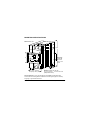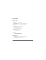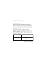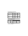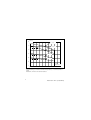
1
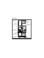
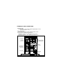
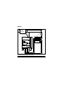
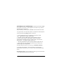
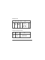
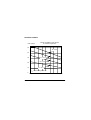
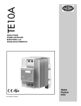
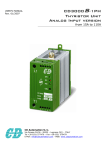
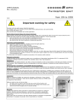
Industrial Solid State Contactor
TE10S
Static switching of resistive loads and
shortwave infrared heating tubes up to 20 kW
Partial load failure (PLF) detection option
User Manual
© Copyright Eurotherm Automation 1996
All rights strictly reserved. No part of this document may be stored in a retrieval system, or
any form or by any means without prior written permission from Eurotherm Automation SA
TE10S/PLF
Part No. HA174784ENG
User Manual
Iss.1
Printed in France 07/96
I
EUROPEAN DIRECTIVES
SAFETY
The TE10S products installed and used in accordance with this User Manual are
designed to comply with the essential protection requirements
of the European Low Voltage Directive 73/23/EEC dated 19/02/73 (amended
by Directive 93/68/EEC dated 22/07/93).
MARK
The CE Mark of TE10S products implies that the essential protection
requirements of the European Low Voltage Directive are observed.
The TE10S Technical Construction File is approved by a Notified Body, LCIE
(Laboratoire Central des Industries Électriques). For further information on CE
Mark, please contact your nearest Eurotherm office.
DECLARATION OF CONFORMITY
A CE Declaration of Conformity is available on request.
ELECTROMAGNETIC COMPATIBILITY (EMC)
For industrial environments, excluding residential environments
The TE10S products are considered as components without any direct function as
defined in the EMC Directive. The system or installation in which these products are
incorporated must complies with the essential protection requirements of
the EMC Directive.
However, Eurotherm certifies that the TE10S products, when installed and used in
accordance with their User Manual, meets the following EMC test standards and
enables the system or installation in which there are installed to comply with the
EMC Directive in regards to the TE10S products.
II
TE10S/PLF User Manual
EMC TEST STANDARDS
Test
EMC test standards
Immunity Electrostatic discharge
IEC 1000-4-2 (EN 61000-4-2) - 06/1995
Fast transients
IEC 1000-4-4 (EN 61000-4-4) - 01/1995
Radioelectric frequency
IEC 801-3 (prEN 61000-4-3) - 1984
electromagnetic fields
Emission Radiated and Conducted EN 55011 - 1991
The choice of the Conducted Emission applicable standard depends
on the application :
• EN 50081-2 - 1991
• IEC 1800-3 (prEN 61800-3) - 1996
Applies for the second environment
FILTER EMC
To reduce the conducted emissions that occur when using thyristor units, the EMC
internal filter is added from April 1996
VALIDATION BY A COMPETENT BODY
In order to guarantee the best service, Eurotherm has validated the compliance of
the TE10S products with these test standards through design and laboratory
tests that have been validated with a Technical Construction File by a competent
body, LCIE (Laboratoire Central des Industries Électriques).
EMC INSTALLATION GUIDE
In order to help you reduce risks related to the effects of electromagnetic
interference depending on the installation of the product, Eurotherm can
supply you with the 'EMC Installation Guide' (Part No. HA 025464).
TE10S/PLF User Manual
III
MANUALS IN USE
• This TE10S/PLF User Manual (Part No. HA174784ENG) applies to TE10S
series with PLF from January 1996.
• The TE10S/PLF User Manual Part No. HA174401 are valid for products
manufactured before this date.
PRECAUTIONS
Read completely this Manual before installation. EUROTHERM cannot be held
responsible for any damage to persons or property, or for any resulting financial loss
or cost caused by the inappropriate product use or the failure to observe this manual.
PERSONNEL
The installation, configuration, commissioning and maintenance of the power unit
must only be performed by a person qualified and authorised to perform
work in an industrial low voltage electrical environment.
INDEPENDENT SAFETY
It is the responsibility of the user and it is highly recommended, given the value of
the equipment controlled using TE10S, to install independent safety devices.
This alarm must be tested regularly.
Eurotherm can supply suitable equipment.
FURTHER INFORMATION
For any further information and if in doubt, please contact your EUROTHERM
office where technicians are at your disposal should you require advice or
assistance with the commissioning of your installation.
IV
TE10S/PLF User Manual
TE10S
Industrial Solid State Contactor for static switching of resistive loads
and shortwave infrared heating tubes up to 20 kW
Partial load failure (PLF) detection option
CONTENTS
page
Installation and use safety ................................................ 2
Technical specifications ................................................... 3
Mounting and dimensions ................................................. 4
Control Signal .................................................................. 5
Front view ......................................................................... 6
Terminals and connectors ................................................. 7
Wiring ................................................................................ 8
PLF Alarm specifications .................................................. 9
Setting up PLF detection ................................................. 10
Ordering code ................................................................. 11
Thyristor protection fuse ................................................. 11
Derating curves ............................................................... 12
TE10S/PLF User Manual
1
INSTALLATION AND USE SAFETY
DANGER !
Failure to take note of the information may have
serious consequences for the safety of personnel and
may even result in the risk of electrocution.
• Installation and use in a correctly cooled electrical cabinet, with
guarantees of protection from condensation and pollution.
The cabinet must be closed and connected to safety earth
conforming to IEC 364 or applicable National Standards.
It is the user's responsibility to ensure that the installation, wiring
and protection of the installation is in accordance with relevant
standards and wiring regulations (e.g. VDE 0160).
• Before making any connections or disconnections make sure that
the cables and wires are insulated from the supply voltage.
• The earth connection must be connected first and disconnected last.
• Control signal wiring must be kept separate from power cables.
• Disconnect the TE10S completely before dismounting.
• The recommended high speed fuse is only designed to protect the
thyristors. It is not a substitute for fuse designed to protect the installation
and wiring. Thyristors are not isolating devices.
It is necessary to provide an additional protection and isolation to
comply with wiring regulations, to allow safe intervention.
• Access to internal parts not allowed to non qualified personnel.
• The temperature of the heatsink may exceed 100°C. Take care
when touching the heatsink and protect it from accidental contact
during ON state and during 15 min after unit disconnection.
2
TE10S/PLF User Manual
TECHNICAL SPECIFICATIONS
Power
Nominal current
Nominal line-to-line voltage
Nominal mains frequency
Firing mode
OFF state leakage current
Input
Command signal
Environmental
Operating temperature
Atmosphere
Humidity
Pollution
Isolation (1min factory test)
Thyristors protection
Unit protection degree
Cooling
Alarm (option)
Mounting
Weight
Guarantee
16, 25, 32 or 40 amps (at 45 °C)
120, 240, 480 or 500 Vac (+10%;-15%)
50 or 60 Hz (±2 Hz)
Logic firing (ON/OFF). Zero crossing
Typical less than 30 mA
Universal DC input (voltage or current)
DC signal 5 V and 5 mA (nominal)
Polarity insensitive '+' and '-' can be crossed
0 to 60°C , altitude 2,000 m maximum
Storage : -10 to 70°C
Non conductive, non explosive, non corrosive
RH : 5 to 95% non condensing
Pollution degree 2 (comply with IEC 664)
Main isolation to earth : 2,000 Vac
Power to control : 3,600 Vac
External fuse, Varistor and RC snubber
IP20 (IEC 529 : §11.4 table 5)
Air natural convection
Partial load failure detection
Vertrical on DIN rail
480g (16A); 660g (25A); 930g (32A); 1060g (40 A)
Two years (see your local representative)
As a result of the constant improvement of its products, Eurotherm may modify
these specifications without warning. For any further information and if in doubt,
please contact your Eurotherm office.
TE10S/PLF User Manual
3
MOUNTING SPECIFICATIONS
Dimensions in mm
92,5
115
80
1
E URO T
LOAD FAIL
.
DEF.CHARG
E
45
2
ε
H E RM
1
ADJUST / REG
L.
2
7 8
5 6
3
3
4
4
52,5 (16A), 70 (25A)
105 (32A), 122,5 (40A)
GN
D
Clip fixing
on DIN rail
EN 50022
35x7.5 and
35x15
Distance between two TE10S :
10 mm up to 45°C, 17.5 mm over 45°C
(adaptor BD173730)
Ground continuity. Due to electromagnetic compatibility requirements make
sure that TE10S mounting DIN rail is bolted to the metal ground (panel or cabinet)
and going on good electrical contact.
4
TE10S/PLF User Manual
INPUT SIGNAL
Command signal
Sygnal type
: DC logic signal.
Universal input :
accepts a voltage or current command signal.
Polarity insensitive, '+' and '-' can be crossed.
ON state :
voltage higher than 5 Vdc and
current higher than 5 mA.
Maximum voltage less than 32 V.
Maximum current (auto limit) :
10 mA at 32 Vdc
OFF state :
voltage less than 2 Vdc or
current less than 0.5 mA.
Signal indication
Command signal indication by green indicator light
(light emitting diode) on front fascia.
TE10S/PLF User Manual
5
FRONT VIEW
Power terminals :
1 to 4
Terminals
1&3:
Controlled
Phase
PLF Alarm
Red
indicator light
1
2
Terminals 2 & 4:
Direct Phase
ε
EUROTHERM
LOAD FAIL.
DEF.CHARGE
ADJUST / REGL.
7
1
2
3
4
8
PLF setting
potentiometer
5 6
Input signal
Green
indicator light
Input pluggable
connector
6
3
4
Safety earth
TE10S/PLF User Manual
TERMINALS AND CONNECTORS
Power terminals :
screw for cable 1.5 to 16 mm2, cable stripping length 16 mm
tightening torque 1.2 N.m
Safety earth wiring :
same cable section as power, tightening torque 2 N.m
Input connection: between terminals 5 & 6
Pluggable connector for cable sizes 0.5 to 1.5 mm2
wire stripping length 7 mm, tightening torque 0.4 N.m
Bottom view
16 mm
PLF alarm 7
contact
connector 8
Power cable
stripping guide
Power
terminals
DC control 5
input signal
6
connector
Fixing clip
Safety earth
screw
DIN rail
TE10S/PLF User Manual
7
WIRING
L
N
Isolation and
protection.
User
installation
Thyristor protection
higt-speed fuse
1A Fuse
2216 controller
TE10S
2
1
EUROTHERM
7 8
V+
2
3
3
N
E
1B
ε
1
5 6
Logic EUROTHERM 2216
output 1A
L
V-
Thermocouple
input
4
4
5 6
PLF alarm
contact
Load
Safety
earth
Input
Example of TE10S wiring (PLF option, 240V nominal).
Controlled by EUROTHERM 2216 controller
8
TE10S/PLF User Manual
PLF SPECIFICATIONS
The 'Partial Load Failure' (PLF) alarm detects an increase in load
impedance due to the breakage, the destruction or the disconnexion of
the heating elements.
The PLF detection is indicated by red indicator light (light emitting
diode) on front fascia.
Partial load failure detection changes the alarm relay state. The relay
is de-energised in the alarm state, or when the TE10S is not powered.
Option PLF : the contact is open in the alarm state;
option IPF : the contact is closed in the alarm state.
Relay contact rating : 0,25 A (250 Vac or 30 Vdc).
Detection sensitivity of partial load failure :
failure detection of 1 element for 6 identical parallel heater elements
(for single-phase applications).
The PLF detection operates under the following conditions:
• firing time ≥ 1 s
• input signal duty cycle must be over 20%
• the on-time load current must be greater than 5 amps
(16 and 25 A nominal) or 8 amps (32 and 40 A nominal).
TE10S/PLF User Manual
9
SETTING UP PLF DETECTIONThe 'Partial Load Failure' (PLF)
alarm detects an increase in load impedance. In order to carry out PLF
adjustment, the current when
fully conducting must be greater than 20% of the nominal unit current.
As a general rule, since the load current is less than the nominal thyristor
current, the following setting must be carried out:
• Check that the thyristors are conducting (load current on and
input green indicator light is illuminated)
• If the PLF detection red indicator light (identified on front as
'Load fail. / Déf. Charge') is illuminated , turn the 25 turn PLF
potentiometer (identified on front as 'Adjust / Régl') anticlockwise
until the PLF red indicator light switches off.
• Turn the potentiometer clockwise until the indicator lights comes on.
• Slowly turn back the potentiometer (anticlockwise) until the red
indicator light is just extinguished.
The PLF detection control is now set to give maximum sensitivity.
If an erratic alarm appears, reduce the sensitivity by turning the
potentiometer anticlockwise (e.g. 1/4 turn or more until the fault disappears).
Resetting the alarm is achieved either by removing power from the unit
or by a returning to the previous load current.
10
TE10S/PLF User Manual
ORDERING CODE
Model
TE10S
/ Current / Voltage / Input
code
code
code
16A
25A
32A
40A
120V
240V
480V
500V
/
LGC
Option
code
/ End
Partial load failure
detection.
00
Alarm relay contact
in alarm state
Open : PLF
Closed : IPF
THYRISTOR PROTECTION FUSE
Current
range
16 A
25 A
32 A
40 A
Fuse
rating
20 A
32 A
40 A
50 A
TE10S/PLF User Manual
Fuse and fuse-holder
code
FU1038 / 16A / 00
FU1038 / 25A / 00
FU1451 / 32A / 00
FU1451 / 40A / 00
11
DERATING CURVES
TE10S max RMS current allowed
vs ambient temperature
I RMS (amps)
50
I N = 40 A
40
30
I N = 32 A
I N = 25 A
20
I N = 16 A
10
I N -current rating (at 45°C)
0
20
12
25
30
35
40
45
50
55 60 (°C)
TE10S/PLF User Manual
Solid State Contactors TE10S
Power Controllers TE10A
ε
EUROTHERM
ADDENDUM
TE10S User Manual Part N°:
HA174780ENG, HA174782ENG,
HA174784ENG, HA175436ENG
TE10A User Manual Part N°:
HA175247ENG, HA175548ENG
NOMINAL CURRENT UP TO 50 A
and
SHORT WAVE INFRARED APPLICATIONS
© Copyright Eurotherm Automation S.A. 1997
All rights strictly reserved. No part of this document may be
stored in a retrieval system, or any form or by any means
without prior written permission from Eurotherm Automation
SA.
Part N°. HA175600 ENG - Issue 2.0 - 12/98
TECHNICAL SPECIFICATION
MAXIMUM CURRENT
In order to take into account supply voltage variations and
heating element resistance dispersion (all types of heating
elements including short wave infrared), a 0.8 safety coefficient
must be used on the thyristor unit current rating to determine the
maximum value of the load nominal current which the unit can
safely control.
SHORT WAVE INFRARED (SWIR) APPLICATIONS
Applications using short wave infrared heaters in Single Cycle,
Fast Cycle or Advanced Single Cycle are reserved to 16 A, 25 A
and 40 A current rating.
With a safety coefficient of 0.8 the maximum current for SWIR
which can be controlled is:
TE10 rating
16 A
25 A
40 A and 50 A
2
SWIR maximum
controlled current
13 A
20 A
32 A
Addendum TE10 (50A/SWIR)
RANGE DIMENSIONS AND WEIGHT
Height 115 mm / Depth 92.5 mm
Nominal
current
Width
(mm)
TE10S/DC, TE10S/AC
TE10S/PDSIO
16 A
25 A
40 A
50 A
35
52.5
87.5
105
350
500
850
1100
TE10S/PLF
TE10A/Burst
TE10A/PA
16 A
25 A
40 A
50 A
52.5
70
105
122.5
550
700
900
1200
Models
Weight
(g)
THYRISTOR PROTECTION FUSE
TE10
rating
16 A
25 A
40 A
50 A
Attention!
Fuse
rating
Code
Dimensions(mm)
20 A
32 A
50 A
63 A
FU1038/16A/00
FU1038/25A/00
FU1451/40A/00
FU2258/50A/00
81 x 17.5 x 68
81 x 17.5 x 68
95 x 26 x 86
140 x 35 x 90
Fuse & fuse-holder
For SWIR applications, the high-speed fuse
must not be used
Addendum TE10 (50A/SWIR)
3
IRMS (A)
60
IN = 50 A
50
IN = 40 A
40
30
IN = 25 A
20
IN = 16 A
10
Operation
tempereature (°C)
0
20
25
30
35
40
45
50
55
60
65
70
Current derating as a fonction of ambient temperature (IN = nominal current at
45°C)
Dotted line : limit due to recommended fuse
4
Addendum TE10 (50A/SWIR)