1
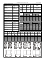
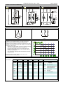
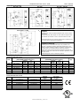
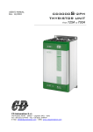
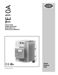
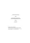
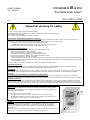
USER’S MANUAL
Rev. 05/2012
CD3000S-2PH
Thyristor Unit
from 10A to 100A
00003
Important warning for safety
Thyristor units are used in power industrial equipment.
The voltages used in the Thyristor unit can cause severe electrical shock, and could be lethal.
Don't remove the plastic cover.
Don't use this unit in aerospace and nuclear application.
Electric Shock Hazard (Risque the choque électrique)
When thyristor unit has been connected to main supply voltage and is switched off, before to touch it be secure that the unit is
isolated and wait at least one minute to allow discharging internal capacitors. Thus be secure that:
•
access to thyristor unit is only permitted to specialised personnel;
•
the authorised personnel must read this manual before to have access to the unit;
•
the access to the unit must be denied to unauthorised personnel.
Important warnings(attention)
Local regulations regarding electrical installation should be rigidly observed.
•
Safety regulations must be rigidly observed.
•
Don't bend components to maintain insulation distances.
•
Protect the unit from high temperature humidity and vibrations.
•
Don't touch components to prevent electrostatic discharges on them.
•
Verify that all rating are in line with real needs.
•
If authorized personnel must measure voltage current etc. on units, take away rings and other jewels from fingers and hands.
•
Authorized personnel working on thyristor unit under power supply voltage must work on insulated board. Be secure that board
is not connected to earth.
This listing does not represent a complete enumeration of all necessary safety cautions.
Protection(protection)
CD3000 thyristor unit has a polymeric plastic cover to compliance to International specification IP20. To understand if IP20
protection is sufficient should be evaluated the installation place. Open Type Equipment.
Earth(terre)
CD3000 family has isolated heatsink. For safety connect the heatsink to earth to avoid shocks in case that circuit board or thyristor
lose insulation. Earth impedance should be correspondent to local earth regulation. Periodically the earth efficiency should be
inspected.
Electromagnetic compatibility (compatibilité électromagnétique)
Our thyristor units have an excellent immunity to electromagnetic interferences if all suggestions contained in this manual are
respected. In respect to a good Engineering practice, all inductive loads like solenoids contactor coils should have a filter in parallel.
Emissions (emission)
All thyristor switching at high speed generate some radiofrequency disturbance. CD3000 series compliance with EMC rules for CE
mark. In many installations near electronic devices have not been noted problems. If radiofrequency devices at low frequency are
used near the thyristor unit some precautions should be taken like line Filters and shielded cables for input signal and for load cables
Installation
Before to install the CD3000 unit examine for damages or deficiencies. If any is found,
notify the carrier immediately. Check that the product features shown on CD3000 cover
corresponds to that ordered.
Before to switch on the unit be sure that:
•
The load current is equal or less than the max current of the thyristor unit.
•
The operating voltage is equal or less than the max voltage of the thyristor unit.
•
Verify the Fan Power Supply (only for size S6 and S8).
Mounting
CD3000 unit should be always mounted in vertical position to improve air cooling on
heatsink. Maintain minimum distances in vertical and in horizontal as represented.
Don't install in proximity of hot elements and near units generating electromagnetic
interferences.
When more units are mounted in the same cabinet provide air circulation as represented.
Sometimes it is necessary to provide a fan to have better air circulation.
CD3000S-2PH from 10A to 100A
User’s manual
TECHNICAL SPECIFICATIONS
General features
Stocking
temperature:
from -40
to +100 °C
from –30
to +40°C
for higher temp.
consult derating
curve
Operating
temperature:
Load isolation:
2500Veff
Cover and Socket
material:
PolymericV2
Heatsink:
Anodized
aluminium
Delay switch ON time:
0.5 period Max
Delay switch OFF time:
Current
Input features
Logic input SSR:
(Standard for size S0 - S1)
Logic input SSR:
(Standard for other sizes)
Logic input SSR:
(low current)
110Vac Input:
240Vac Input:
26.6 (3.0)
8
UL Listed (ZMVV)
Wire Pin
45A,75A,
100A
M6 Screw
70.8 (8.0)
1
UL Listed (ZMVV)
Fork/Spade Terminal
Copper Tube Crimp. Lug
Supply
Cable
mm2
AWG
4
12
Load
Cable
mm2
AWG
4
12
Screw
M
M5
Screw
M
M5
15A (S1)
4
12
M5
4
12
25A (S1)
6
10
M5
6
10
M5
M5
35A (S4)
10
8
M5
10
8
M5
45A (S7)
10
8
M6
10
8
M6
75A (S8)
25
4
M6
25
4
M6
100A (S8)
35
3
M6
35
3
M6
10A (S0)
Auxiliary
Cable
mm2
AWG
0,50
18
15A (S1)
0,50
18
4
12
M5
25A (S1)
0,50
18
6
10
M5
35A (S4)
0,50
18
6
10
M5
45A (S7)
0,50
18
6
10
M5
75A (S8)
0,50
18
6
10
M5
100A (S8)
0,50
18
6
10
M5
Current
Earth
Cable
mm2
AWG
4
12
Screw
M
M5
Repetitive peak
reverse
Voltage
Latching
current
Max peak
one cycle
Leakage
current
I2T value
thyristor
Frequency
range
Power loss
Isolation
Voltage
(V)
480V
600V
(mAeff)
(10ms) (A)
(mAeff)
tp=10msec
(Hz)
I=Inom
(W)
Vac
10A (S0)
24÷480
1200
1200
150
230
15
610
47÷70
20
2500
15A (S1)
24÷480
1200
1200
150
230
15
610
47÷70
36
2500
25A (S1)
24÷480
1200
1200
150
230
15
610
47÷70
60
2500
35A (S4)
24÷600
1200
1600
250
600
15
1800
47÷70
88
2500
45A (S7)
24÷600
1200
1600
450
1000
15
4750
47÷70
108
2500
75A (S8)
24÷600
1200
1600
450
1350
15
8830
47÷70
180
2500
100A (S8)
24÷600
1200
1600
450
2000
15
19100
47÷70
240
2500
Size
Voltage
range
(A)
S0
S1
Ø4,5mm
30
30 mm
S4
Ø4,5mm
110 mm
120 mm
110 mm
120 mm
4 - 30Vdc 20mA Max
(ON ≥ 4Vdc
OFF < 1Vdc)
4 - 30Vdc 12mA Max
(ON ≥ 4Vdc
OFF < 1Vdc)
5 - 30Vdc 5mA Max
(ON ≥ 5Vdc
OFF < 1Vdc)
110Vac ±15%
20mA Max
230Vac ±15%
20mA Max
Wire
Terminal
M5 Screw
10A (S0)
230Vac ±15%
(110Vac option.)
Wire
Range
AWG/kcmill
10A,15A,
25A,35A
Current
0.5 period Max
Fan voltage:
(Only for size S8)
Connector
Torque
Type
Lb-in (N-m)
60 mm
65 mm
120 mm
S7
Ø4,5mm
110 mm
117 mm
65 mm
120 mm
S8
Ø4,5mm
110 mm
65 mm
138 mm
110 mm
117 mm
117 mm
120 mm
123 mm
159 mm
Ø4,5mm
159 mm
CD3000S-2PH from 10A to 100A
User’s manual
DIAGRAM OF CONTROL CONNECTION
Size S0
Size S1
L1
L2
L3
L1
L2
L3
L1
L2
L3
L1
L2
L3
*
L2
Input:
+ SSR
-
T1
A2+
A1-
T2
Fan Power
Supply
(for size S8)
L1
L2
L3
FAN
POWER UNIT
A1-
POWER UNIT
L1
TO LOAD
L1
L2
L3
*
POWER UNIT
*
Size S4, S7 e S8
L1
L2
L3
Input:
+ - SSR
~ ~ 110Vac
~ ~ 230Vac
A2+
T1
T3
T2
TO LOAD
Fan Power
Supply
(for size S8)
Input:
+ - SSR
~ ~ 110Vac
~ ~ 230Vac
A1- A2+
TO LOAD
* The user installation must be protecting by electromagnetic circuit breaker or by fuse isolator.
Load Type
Delta
Star
Wiring instructions
CD3000S unit has isolated heatsink. For safety connect the
heatsink to hearth using its terminal with hearth symbol.
CD3000S can be susceptible to airborne interferences from near
equipment or from interferences on main supply, so a number of
precautions must be taken.
•
Contactors coils and chokes must have in parallel a RC filter
and must be supplied with a different voltage line.
•
All input/output signals must use screened bifilar wires.
•
Signal input and output must not route in same cable try
and must not be parallel.
•
Local regulations regarding electrical installation should be
rigidly observed
Derating curve
Use copper cables and wires rated for use at 75 °C only.
Use wire terminal UL Listed (ZMVV)
Order Code
CD3000S-2PH
Current
Operating
Voltage
MAX
Volt
Aux
480Vac
15A
Operating
600Vac
25A
Voltage
35A
<=
NF
No fuses
45A
MAX Volt
UL
UL Certification
M Only for size from 35A to 100A
ZC
Options
110v
Fan
Write
100A
SSR
Firing
10A
75A
NO
Input
110Vac
EP
230Vac
EF
Fan at 110Vac
External Protection IP20
for size S7 and S8
External fuses and
fuse holders
CD3000S-2PH from 10A to 100A
FUSES AND FUSE HOLDER
Size 15A - 25A
Size 35A
User’s manual
Size 45A - 75A(CE)
Size 75A(UL) - 100A
WARNING
CD3000S unit must be protected against short circuit by High
speed fuses.
The fuses must be with proper I²t lower than the thyristor one.
The warranty of thyristor is null if no proper fuses are used.
High speed fuses are only used for the thyristor protection and
can not be used to protect the installation
WARRANTY CONDITION
Producer gives a 12 months warranty to its products. The
warranty is limited to repairing and parts substitution in our
factory and does exclude products not properly used and fuses.
Warranty does not include products with serial numbers
deleted. The faulty product should be shipped to Producer at
customer’s cost and our Service will evaluate if product is under
warranty terms.
Substituted parts remain of Producer property.
Fuses and Fuse Code for UL
Size
10A
15A
25A
35A
45A
75A
100A
Bussmann Div Cooper (UK) Ltd
(200 kARMS Symmetrical A.I.C.)
Current
I²T
Fuse CODE
(ARMS)
(A²sec)
FWC 16A10F
16
150
FWC 16A10F
16
150
FWC 32A10F
32
600
FWP 40A14F
40
750
FWP 63A22F
63
3080
-
Vac
600
600
600
700
700
-
Ferraz Shawmut SA
(200 kARMS Symmetrical A.I.C.)
Current
I²T
Fuse CODE
(ARMS)
(A²sec)
660 Grb 10-16
16
145
660 Grb 10-16
16
145
660 Grb 10-32
32
740
CP URC 14x51/40
40
700
CP URD 22x58/63
63
1850
CP URQ 27x60/100
100
3210
CP URQ 27x60/160
160
15000
Qty
Vac
660
660
660
660
660
660
660
3
3
3
3
3
3
3
Fuses and Fuse Code for CE
Size
Fuse and Fuse holder CODE
Fuse CODE
10A
15A
25A
35A
45A
75A
100A
FFH1038/16A
FFH1038/16A
FFH1038/32A
FFH1451/40A
FFH2258/50A
FFH2258/100A
FFH2258/125A
FU1038/16A
FU1038/16A
FU1038/32A
FU1451/40A
FU2258/50A
FU2258/100A
FU2258/125A
Current
(ARMS)
16
16
32
40
50
100
125
I²T (max)
(A² sec.)
150
150
600
1650
2000
13500
14000
C
UL
®
LISTED
Neut-Eng-CD3000S-2PH__10-100A - 06
US