1
Operators Manual / Guide D'utilisation / Manual Del Operario
EN p. 2
14" Dual Line Grass Trimmer GT1415
FR p. 21
Coupe-gazon Double Fil 355,6 mm (14 pouces) GT1415
SP p. 41
Bordeadora De Cable Doble De 14" GT1415
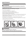
Do not use ANY
attachments with this trimmer
N'utiliser AUCUN accessoire
avec ce coupe-gazon
No utilice NINGUN aditamento
con esta bordeadora
MNL_GT1415_V1
Read all safety rules and instructions carefully before operating this tool.
Distributed By Cleva North America 601 Regent Park Court Greenville, SC 29607 (866)-384-8432
Lisez attentivement les règles de sécurité et les instructions avant d’utiliser cet outil.
Distribué par Cleva North America 601 Regent Park Court Greenville, SC 29607 (866)-384-8432
Lea cuidadosamente todas las normas de seguridad e instrucciones antes de utilizar esta herramienta.
Distribuida por Cleva North America 601 Regent Park Court Greenville, SC 29607 (866)-384-8432
3084514
Conforms to UL STD 82
Certified to CAN/CSA STD.
C22.2 No. 147-M90
CONTENTS
Contents
2
Product Specifications
2
General Safety Rules
3-4
Electrical Information
5-7
Symbols
7-8
Know Your String Trimmer
9
Assembly
10-11
Operation
12-13
Maintenance
14-15
Troubleshooting
16
Warranty
17
Exploded View
18
Parts List
19
Notes
20
SPECIFICATIONS
14" DUAL LINE GRASS TRIMMER
Voltage
120 V ~ 60 Hz
Amp
7 Amp
Revolutions Per Minute
7,000 rpm
Line Diameter
0.065 inch(1.65mm)
Cutting Width
14 inch
Weight
7.1 lbs (3 kg)
2
GENERAL SAFETY RULES
WARNING
When using the grass trimmer the safety rules must be followed.
For your own safety and bystanders please read these instructions before
operating the grass trimmer. Do not use the grass trimmer without reading the
instruction sheet. Please keep the instructions safe for later use.
edges in private and hobby garden areas which are not accessible with a grass trimmer.
well as in agriculture and forestry.
injury.
- Hedges, shrubs and bushes,
- Flowers,
- In terms of composting.
sensory or mental capabilities, or lack of experience and knowledge, unless they have been given
supervision or instruction concerning use of the appliance by a person responsible for their safety.
similarly qualified persons in order to avoid a hazard.
!
"
#
$
%
repair as necessary.
"
&
the motor.
'
*
extending new cutter line always return the grass trimmer to its normal operating position before
switching on.
"
"
+
grass trimmer and when it is not in use.
*
3
GENERAL SAFETY RULES
ADDITIONAL SAFETY INSTRUCTIONS FOR YOUR GRASS TRIMMER
Do not expose to moisture.
Use only on AC mains supply voltage shown on the product rating label.
Avoid operating your trimmer in wet grass, where feasible.
Take care in wet grass, you may lose your footing.
On slopes, be extra careful of your footing and wear nonslip footwear.
Do not walk backwards when trimming, you could trip. Walk never run.
Switch off before pushing the trimmer over surfaces other than grass.
Never pick up or carry a trimmer by the power cord.
Do not lean over the trimmer guard objects may be throw by the cutting line.
Keep all nuts, bolts and screws tight to be sure the trimmer is in safe working condition.
To avoid the risk of injury keep fingers and hands clear of the trimmer line on the leading edge of
the guard.
MAINTENANCE
After use, disconnect the machine from the power supply and check for damage.
When not in use store the machine out of the reach of children.
Electric powered trimmers should only be repaired by an authorised repairer.
Use only manufacturers recommended replacement parts and accessories.
The preparation for use, operation and maintenance of the tool:
- Read the instructions carefully;
- Be familiar with the controls and proper use of the equipment;
- Before use check the supply and extension cord for signs of damage or ageing,
- If the cord becomes damaged during use, disconnect the cord from the power supply
immediately.
DO NOT TOUCH THE CORD BEFORE DISCONNECTING THE SUPPLY;
- Do not use the lawn trimmer (edge trimmer), if the cords are damaged or worn.
WARNING
- Cutting elements continue to rotate after the motor is switched off;
- Keep extension cords away from cutting elements;
- It is recommended that appliances should be supplied via a residual
current device (RCD) with a tripping current of not more than 30mA.
- This equipment must not be used for composting purposes (shredding)
as this could result in injury or damage to property.
4
ELECTRICAL INFORMATION
WARNING
TO AVOID ELECTRICAL HAZARDS, FIRE HAZARDS, OR DAMAGE TO THE
TOOL, USE PROPER CIRCUIT PROTECTION. YOUR GRASS TRIMMER IS
WIRED AT THE FACTROY FOR 120 V OPERATION. CONNECT TO A 120 V,
15 A CIRCUIT, AND USE A 15 A TIME-DELAYED FUSE OR CIRCUIT
BIREAKER. TO AVOID SHOCK OR FIRE, IF THE EXTENSION CORD IS
WORN, CUT OR DAMAGED IN ANY WAY, REPLACE IT IMMEDIATELY.
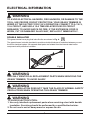
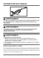
DOUBLE INSULATED
This grass trimmer has a plug that looks like the one shown in Fig. A
The grass trimmer is double insulated to provide a double thickness of insulation between you and
the tool’s electrical system. All exposed metal parts are isolated from the internal metal motor
components with protective insulation.
Fig. A
WARNING
USE ONLY IDENTIFICAL REPLACEMENT PARTS WHEN SERVICING THE
GRASS TRIMMER, TO AVOID INJURY.
WARNING
DOUBLE INSULATION DOES NOT TAKE THE PLACE OF NORMAL SAFETY
PRECAUTIONS WHEN OPERATING THIS GRASS TRIMMER
WARNING
TO AVOID ELECTROCUTION:
1. Use only identical replacement parts when servicing a tool with double
insulation. Servicing should be performed by a qualified technician.
2. Do not use in wet or damp areas or expose to rain.
5
ELECTRICAL INFORMATION
GROUNDING INSTRUCTIONS
IN THE EVENT OF A MALFUNCTION OR BREAKDOWN, grounding provides the path of least
resistance for electric current, and reduces the risk of electric shock. This tool is equipped with a
POLARIZED plug. The plug MUST be plugged into a matching grounded extension cord in
accordance with All local codes and ordinances.
DO NOT MODIFY THE PLUG PROVIDED. If it will not fit the properly grounded extension cord,
have the proper outlet installed by a qualified electrician.
CAUTION
ALWAYS MAKE SURE THAT YOUR OUTLET IS PROPERLY GROUNDED.
IF UNCERTAIN, HAVE IT CHECKED BY A CERTIFIED ELECTRICIAN.
WARNING
THIS GRASS TRIMMER IS FOR OUTDOOR USE ONLY. DO NOT EXPOSE
TO RAIN OR USE IN DAMP LOCATIONS.
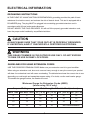
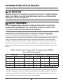
GUIDELINES FOR USING EXTENSION CORDS
USE THE PROPER EXTENSION CORD. Make sure your extension cord is in good condition.
When using an extension cord, be sure to use one heavy enough to carry the current your product
will draw. An undersized cord will cause overheating. The table below shows the correct size to use
depending on cord length and nameplate ampere rating. If in doubt, use the next heavier gauge.
The smaller the gauge number, the heavier the cord.
Minimum Gauge for Extension Cords (AWG)
(when using 120 V only)
Ampere Rating
More Than Not More Than
Total Length of Cord in Feet (meters)
25’ (7.6 m)
50’ (15 m) 100’ (30.4 m) 150’ (45.7 m)
0
6
18
16
16
14
6
10
18
16
14
12
10
12
16
16
14
12
12
16
14
12
Not Recommended
6
ELECTRICAL INFORMATION
Make sure your extension cord is properly wired and in good electrical condition. Always replace a
damaged extension cord or have it repaired by a qualified person befor ues. Keep extension cords
away from sharp objects, excessive heat and damp or wet areas.
Use a separate electrical circuit for your tools. This circuit should comprise a wire of at least 12
gauge and should be protected with a 15 A time-delayed fuse. Before connecting the motor to the
power line, make sure the switch is in the OFF position and the electric current is identical to that
stamped on the motor nameplate. Running at a lower voltage will damage the motor.
WARNING
ALTHOUGH THIS GRASS TRIMMER IS DOUBLE INSULATED, THE
EXTENSION CORD AND RECEPTACLE MUST STILL BE GROUNDED
WHILE IN USE TO PROTECT THE OPERATOR FROM ELECTRICAL
SHOCK.
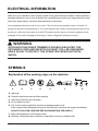
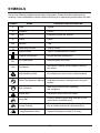
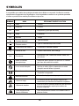
SYMBOLS
Explanation of the warning signs on the machine.
A
B
C
D
E
F
G
A : Warning!
B : Read the instruction manual before starting!
C : Wear eye protection and ear plugs!
D : Do not expose to rain!
E : Pull out the mains plug before checking a damaged power cord!
If the cord becomes damaged during use, disconnect the cord from the supply immediately.
DO NOT TOUCH THE CORD BEFORE DISCONNECTING THE SUPPLY!
F : Keep other people out of the danger area!
G : Warning. Cutting elements continue to rotate after the motor is switched off!
7
SYMBOLS
Some of the following symbols may be used on this product. Please study them and learn their
meaning. Proper interpretation of these symbols will allow you to operate the product better and safer.
SYMBOL
NAME
DESIGNATION/EXPLANATION
V
Volts
Voltage
A
Amperes
Current
Hz
Hertz
Frequency (cycles per second)
W
Watts
Power
Minutes
Time
Alternating Current
Type of current
Direct Current
Type or a characteristic of current
Class II Construction
Double-insulated construction
no
No Load Speed
Rational speed, at no load
/min
Per Minute
Revolutions, strokes, surface speed, orbits etc.,
per minute
Wet Conditions Alert
Do not expose to rain or use in damp locations
Read The Operator’s Manual
To reduce the risk of injury user must read and
understand operator’s manual before using this
product.
Eye Protection
Wear eye protection when operating
this equipment.
Safety Alert
Precautions that involve your safety.
Long Hair
Failure to keep long hair away from the air inlet
could result in personal injury.
Loose Clothing
Failure to keep loose clothing from being drawn
into air intake could result in personal injury.
Keep Bystanders Away
Keep all bystanders at least 50 ft. away.
min
8
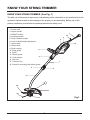
KNOW YOUR STRING TRIMMER
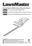
KNOW YOUR STRING TRIMMER (See Fig. 1)
The safe use of this product requires an understanding of the information on the product and in this
operator’s manual as well as a knowledge of the project you are attempting. Before use of this
product, familiarize yourself with all operating features and safety rules.
1. Power cord
2. Upper handle
3. ON/OFF switch
4. Auxiliary handle
5. Quick release coupler
6. Lock for shaft height adjustment
7. Upper shaft
8. Lower shaft
9. Shaft coupler
4
10. Edge guide
11. Spool
12. Debris guard
6
13. Cord retainer
14. Hex Key
15. Trimmer Line
16. Screw for mounting the debris guard
1
14
2
3
13
7
5
9
8
16
10
12
15
Fig.1
11
9
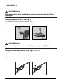
ASSEMBLY
WARNING
Before assembly, make sure that the grass trimmer is switched off and
unplugged.
Fitting the guard (See Fig. 2 & Fig. 3)
1. Fit the debris guard onto the motor head as shown.
2. Fasten the debris guard with a screw and the Hex key.
Fig. 2
Fig. 3
WARNING
Never use the grass trimmer unless the guard is properly fitted.
Fitting the secondary handle (See Fig. 4 & Fig. 5)
1. Place the handle on the grass trimmer as shown.
2. Adjust the handle to the most comfortable position. Use the marking as a guide.
3. Pass the bolt through the secondary handle and the main handle.
4. Screw the nut into the other side of the bolt. Do not over tighten the bolt.
Fig. 4
Fig. 5
10
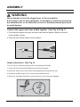
ASSEMBLY
WARNING
Never attempt to lock the trigger lever in the on position.
If the power cord for this equipment is damaged, it must be replaced by
the manufacturer or its aftersales service or similarly trained personnel
to avoid danger.
Connect the upper and lower shafts together (See Fig. 6 & Fig. 7)
1. Push and plug together the upper and lower shaft sections together. Make sure that the
bump engages correctly.
2. Press the quick release coupler into the position.
Fig. 6
Fig. 7
Height adjustment (See Fig. 8)
You can set your optimal working position by adjusting the height.
1. Press the lock for the shaft adjustment and keep it pressed.
2. Move the shaft to one of the three locking positions and release the lock.
3. Rotate the shaft through 180° to the left and release the lock.
4. Move the shaft back and forth to ensure that the lock is correctly engaged.
Fig. 8
11
OPERATION
Hint for optimum use
(See Fig. 9)
Trimming
=
>
!
'
Adjusting cutting head angle (See Fig.10)
Depress the button and move the shaft to the lowest position, the shaft will rotate to the 4
position, while release the button. When the shaft is in position, the button will lock into place.
Using the Edge Guide (distance bracket) (See Fig. 11)
If necessary the distance bracket can be swung down until it engages. Use the distance bracket,
for example, to cut around plants.
Fig. 9
Fig. 10
Fig. 11
IF GRASS BECOMES WRAPPED AROUND STRING HEAD SHAFT:
#
?
@
NOTE: Always remove any debris that becomes wrapped around the shaft.
NOTE: This trimmer is NOT meant for ANY attachments whatsoever!!
12
OPERATION
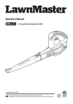
ADVANCING STRINGS
NOTE: Trimmer is equipped with an auto-feed head.
Do not bump the head to try to advance the line will damage trimmer and
void warranty.
!
!
NOTE: The strings will extend approximately 3/16 in.
with each stop and start of the switch trigger until the strings reach the
length of the grass deflector blade.
Do not cut grass when it is wet. The best results are had on dry grass.
NOTE: It may take up to 10 times of starting and stopping the trimmer
before the line advances all the way and is working properly.
NOTE: Do not move the grass trimmer against the grass until the switch
is pressed, i.e. wait until the trimmer is running.
J
at an angle of approx. 30° as you do so (see Fig. 12 & Fig. 13).
[
(see Fig. 14).
Fig. 12
Fig. 13
13
Fig. 14
MAINTENANCE
Your grass trimmer has been designed to operate over a long period of tome with a minimum of
maintenance. Continuous satisfactory operation depends upon proper tool care and regular cleaning.
WARNING
Before performing any maintenance, switch off and unplug the tool.
Regularly clean the ventilation slot in your grass trimmer using a soft brush or
dry cloth.
Regularly clean the cutting line and spool using a soft brush or dry cloth.
Regularly use a blunt scraper to remove grass and dirt from the underneath
of the guard.
Fitting a new spool of cutting line
(See Fig. 15 & Fig. 16)
?
&
① depress thumb tabs and remove the spool cover
② from the housing
③ Remove the empty. spool
④ from the spool cover .
@
@
until it is seated.
?
⑤. The
line should protrude approx. 4 inches from the spool cover.
?
should produce approx. 4 inches from the spool corner.
*
① on the spool cover with the cut outs ④ in the housing.
\
ķ
ĸ
Ĺ
ĺ
Ļ
ķ
ĸ
Fig. 15
Fig. 16
Ĺ
ĺ
Ļ
14
MAINTENANCE
WARNING
If the cutting lines protrude beyond the trimming blade, cut them off so
that they just reach the blade.
Winding new line onto a spool (See Fig. 17 - Fig. 19)
$use .065" replacement line
You may wind new cutting line onto an empty spool.
Replacement packs of cutting line are available from dealer.
Remove the empty spool from the grass trimmer as described above.
Remove any remaining cutting line from the spool.
First feed 4 inches of cutting line ⑥ into the two eyelet ⑦ in the upper section of the spool as show
Wind the cutting line onto the spool in the direction of the arrow. make sure to wind the line on
neatly and in layers. Do not criss-cross.
Feed cutting line ⑥ into the two eyelet ⑦ in the upper section of the spool as show
Finish winding, Produce as described above to fit the spool on the grass trimmer. Do not forget to
release the cutting line from the parking slot.
Use LawnMaster replacement spool; part # RS0101
ļ
Ľ
Fig. 17
Fig. 18
Fig. 19
WARNING
Only use the appropriate type of cutting line.
Bits of the cutting line could cause injury when being flung out.
15
TROUBLESHOOTING
If your grass trimmer seems not to operate properly, follow the instruction
below. If this does not solve the problems, please call 1-866-384-8432
WARNING
Before proceeding, switch off and unplug.
The machine will not work
$&
{
service address.
Tool runs slowly
`
cut it off so that it just reaches the line trimming blade.
Automatic line feed does not work.
&
\
`
the spool, install a new spool of cutting line as instructed above.
*
\
'
'
|
@
@
Replace the spool as instructed.
Disposal and recycling
material and can therefore be reused or can be returned to the raw material system.
Defective components must be disposed of as special waste. Ask your dealer or your local council.
16
WARRANTY
We take pride in producing a high quality, durable product. This Lawnmaster® product carries a
limited two (2) year warranty against defects in workmanship and materials from date of purchase
under normal household use. If product is to be used for commercial, industrial or rental use, a 30
day limited warranty will apply. Batteries carry a one-year warranty against defects in workmanship
and materials. Batteries must be charged in accordance with the operator's manual directions and
regulations in order to be valid. Warranty does not apply to defects due to direct or indirect abuse,
negligence, misuse, accidents, repairs or alterations and lack of maintenance. Please keep your
receipt/packing list as proof of purchase. This warranty gives you specific legal rights, and you
may have other rights, which vary from state to state. For product service call Customer Service at
(866) 384-8432.
Items not covered by warranty :
1. Any part that has become inoperative due to misuse, commercial use, abuse, neglect, accident,
improper maintenance, or alteration;
2. The unit, if it has not been operated and/or maintained in accordance with the owner's manual;
3. Normal wear, except as noted below;
4. Routine maintenance items such as lubricants, blade sharpening;
5. Normal deterioration of the exterior finish due to use or exposure.
Transportation Charges :
Transportation charges for the movement of any power equipment unit or attachment are the
responsibility of the purchaser. It is the purchaser’s responsibility to pay transportation charges for
any part submitted for replacement under this warranty unless such return is requested in writing
by LawnMaster.
SAVE YOUR RECEIPTS. THIS WARRANTY IS VOID WITHOUT THEM.
17
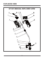
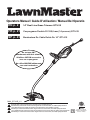
EXPLODED VIEW
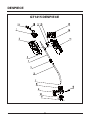
GT1415 MANUAL EXPLODED VIEW
18
PARTS LIST
GT1415 MANUAL PARTS LIST
ITEM NO.
PART NO.
DESCRIPTION
QTY
1
GT70RM.10.00
Motor assembly
1
2
GT70FM.A0.01
Right motor housing assembly
1
3
TOTHYY.06.07
Pressed spring
1
4
GT72RM.20.00
Upper telescopic shaft assembly
1
5
GT72RM.20.40
Shaft coupler assembly
1
6
GT72RM.30.00
Lower shaft assembly
1
7
BOD1YZ.05.25
Spare spool lock
1
8
GT70RM.40.00
Output connector
1
9
GT72RM.50.00
Debris guard assembly
1
10
GT70RM.70.00
Spool head assembly
1
11
GT01FM.31.00
Spool (replacement part #RS0101)
1
12
GT72RM.00.08
Flower guard
1
13
GT70FM.A0.02
Left motor housing assembly
1
14
TOQTGX.A0.01
Impacted plate assembly
1
15
GT01FM.10.00
Auxiliary handle assembly
1
16
WODQ10.03.06
Switch
1
17
GT70RM.A0.09
Switch button
1
18
GT70RM.00.08
Hex key
1
19
TODQ80.45.00
Power cord assembly
1
19
NOTES
20
SOMMAIRE
Sommaire
21
Caractéristiques Du Produit
21
Règles De Sécurité Générales
22-24
Informations Électriques
24-27
Symboles
27-28
Connaissez Votre Débroussailleuse
29
Montage
30-31
Fonctionnement
32-33
Maintenance
34-35
Dépannage
36
Garantie
37
Vue Éclatée
38
Liste Des Pièces
39
Notes
40
CARACTÉRISTIQUES DU PRODUIT
COUPE-GAZON DOUBLE FIL 355,6 mm (14 pouces)
Tension
120 V ~ 60 Hz
Intensité
7A
Vitesse
7 000 tours/minute
Diamètre du fil
1,65 mm (0,065 pouce)
Largeur de coupe
355,6 mm (14 pouces)
Poids
7,1 lb (3 kg)
21
RÈGLES DE SÉCURITÉ GÉNÉRALES
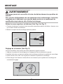
AVERTISSEMENT
Les règles de sécurité doivent être respectées quand vous utilisez la
débroussailleuse. Pour votre propre sécurité et celles des personnes
avoisinantes, veuillez lire ces instructions avant d’utiliser la débroussailleuse.
N’utilisez pas la débroussailleuse sans lire la fiche d’instructions. Veuillez conserver les instructions
pour une utilisation ultérieure.
pour tailler les bordures d’herbe dans les jardins privés et amateurs, inaccessibles avec une tondeuse.
'
route ainsi que dans l’agriculture et la foresterie.
de blessures.
- Haies, arbrisseaux et arbustes,
- Fleurs,
- En termes de compostage.
des capacités physiques, sensorielles ou mentales réduites, ou un manque d’expérience et de
connaissance, sauf si une personne responsable de leur sécurité les supervise ou leur a donné les
instructions pour l’utilisation de l’appareil.
'
#
service ou une personne de qualification similaire pour éviter tout risque.
\
"
'
débroussailleuse.
*
proximité
?
'
*
ou de dégâts et réparez si nécessaire.
"
'
[
'
allumez le moteur.
\
filament. Après avoir ajouté une nouvelle ligne de coupe, remettez toujours la débroussailleuse
dans sa position de fonctionnement normale avant de l’allumer.
22
RÈGLES DE SÉCURITÉ GÉNÉRALES
"
'
"
'
le fabricant.
+
{
{
*
{
'
INSTRUCTIONS DE SÉCURITÉ SUPPLÉMENTAIRES POUR VOTRE
DÉBROUSSAILLEUSE
"
?
*
#
J
#
antidérapantes.
"
[
'
"
'{
"
{
'
projetés par la ligne de coupe.
[
est en bon état d’utilisation.
*
de coupe, sur le bord de la protection.
MAINTENANCE
*
{
{
?
Préparation: utilisation, fonctionnement et entretien de l'outil:
- Lisez attentivement les instructions;
- Connaissez bien les commandes et l’utilisation appropriée de l’équipement;
- Avant l’utilisation, vérifiez si l’alimentation et le cordon présentent des signes de dommages ou
d’usure;
- Si le cordon est endommagé pendant l’utilisation, déconnectez-le immédiatement du secteur.
NE TOUCHEZ PAS LE CORDON AVANT D’AVOIR DÉCONNECTÉ LE SECTEUR;
- N’utilisez pas la débroussailleuse (coupe-bordure) si les cordons sont endommagés ou usés.
23
RÈGLES DE SÉCURITÉ GÉNÉRALES
AVERTISSEMENT
- Les éléments coupants continuent de tourner après l’arrêt du moteur;
- Maintenez les cordons prolongateurs à l’écart des éléments coupants;
- Il est recommandé d’alimenter les appareils avec un dispositif différentiel
à courant résiduel (DDR) avec un courant de déclenchement ne dépassant
pas 30 mA.
- Cet équipement ne doit pas être utilisé pour la fabrication de compost
(déchiquetage). Des blessures corporelles ou des dommages matériels
pourraient survenir.
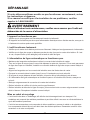
INFORMATIONS ÉLECTRIQUES
AVERTISSEMENT
POUR ÉVITER LES DANGERS ÉLECTRIQUES, D’INCENDIE OU DE
DOMMAGES DE L’OUTIL, UTILISEZ UNE PROTECTION DE CIRCUIT
APPROPRIÉE. VOTRE DÉBROUSSAILLEUSE EST CÂBLÉE À L’USINE
POUR UN FONCTIONNEMENT À 120 V. CONNECTEZ-LA À UN CIRCUIT
120 V, 15 A ET UTILISEZ UN DISJONCTEUR OU UN FUSIBLE À
RETARDEMENT 15 A. POUR ÉVITER L’ELECTROCUTION OU LE RISQUE
D’INCENDIES, SI LE CORDON DE PROLONGEMENT EST USÉ, COUPÉ OU
ENDOMMAGÉ DE TOUTE MANIÈRE, REMPLACEZ-LE IMMÉDIATEMENT.
DOUBLE ISOLATION
Fig. A
électrique de l’outil. Toutes les parties métalliques exposées sont isolées des composants métalliques
internes du moteur par une isolation de protection.
24
INFORMATIONS ÉLECTRIQUES
Fig. A
AVERTISSEMENT
UTILISEZ UNIQUEMENT DES PIÈCES DE RECHANGE IDENTIQUES LORS
DE L’ENTRETIEN DE LA DÉBROUSSAILLEUSE AFIN D’ÉVITER LES
BLESSURES.
AVERTISSEMENT
LA DOUBLE ISOLATION NE REMPLACE PAS LES PRÉCAUTIONS DE
SÉCURITÉ NORMALES LORS DE L’UTILISATION DE CETTE
DÉBROUSSAILLEUSE.
AVERTISSEMENT
POUR ÉVITER L’ÉLECTROCUTION :
1. Utilisez uniquement des pièces de rechange identiques lors de
l’entretien d’un outil avec une double isolation. L’entretien doit être
effectué par un technicien qualifié.
2. Ne l’utilisez pas dans des zones mouillées ou humides et ne l’exposez
pas à la pluie.
INSTRUCTIONS DE MISE À LA TERRE
'
@
pour le courant électrique et réduit le risque de décharge électrique. Cet outil est équipé D’une prise
25
INFORMATIONS ÉLECTRIQUES
ATTENTION
ASSUREZ-VOUS TOUJOURS QUE VOTRE SORTIE EST CORRECTEMENT
MISE À LA TERRE. EN CAS D’INCERTITUDE, FAITES-LA CONTRÔLER
PAR UN ÉLCTRICIEN CERTIFIÉ.
AVERTISSEMENT
CETTE DÉBROUSSAILLEUSE EST PRÉVUE POUR UNE UTILISATION
EXTÉRIEURE UNIQUEMENT. NE L’EXPOSEZ PAS À LA PLUIE ET NE
L’UTILISEZ PAS DANS DES ENDROITS HUMIDES.
DIRECTIVES D’UTILISATION DES CORDONS DE PROLONGEMENT
?#?"$@+$"+\@$$">["*\\@$\@*
{
prolongement est en bon état. Lorsque vous utilisez un cordon de prolongement, assurez-vous d’en
?
{
fonction de la longueur du cordon et de l’intensité indiquée sur la plaque signalétique. En cas de
doute, utilisez le calibre de capacité supérieure. Plus le numéro de calibre est petit, plus le cordon
est fort.
Calibre minimum pour les cordons de prolongement (AWG)
(pour 120 V uniquement)
Intensité
Longueur de cordon totale en pieds (mètres)
Plus De
Pas Plus De
25’ (7.6 m)
0
6
18
16
16
14
6
10
18
16
14
12
10
12
16
16
14
12
12
16
14
12
Non Recommandé
50’ (15 m) 100’ (30.4 m) 150’ (45.7 m)
Assurez-vous que votre cordon de prolongement est correctement connecté et dans un bon état
électrique. Remplacez toujours un cordon de prolongement endommagé ou faites-le réparer par
[
objets coupants, d’une chaleur excessive ou de zones mouillées.
26
INFORMATIONS ÉLECTRIQUES
INFORMATIONS ÉLECTRIQUES
?
**
{
$JJ
plus basse endommagerait le moteur.
AVERTISSEMENT
BIEN QUE CETTE DÉBROUSSAILLEUSE AIT UNE DOUBLE ISOLATION,
LE CORDON DE PROLONGEMENT ET LE RÉCEPTACLE DOIVENT ÊTRE
MIS À LA TERRE PENDANT L’UTILISATION AFIN DE PROTÉGER
L’OPÉRATEUR D’UNE DÉCHARGE ÉLECTRIQUE.
SYMBOLES
Explication des signes d'avertissement portés sur la machine.
A
B
C
D
E
F
G
A : Attention!
B : Lisez le manuel d’instructions avant utilisation!
C|\
D|"
E : +
Si le cordon est endommagé pendant l’utilisation, débranchez-le immédiatement de la source
d’alimentation.
NE TOUCHEZ PAS LE CORDON AVANT DE L'AVOIR DÉBRANCHÉ DE LA SOURCE
D’ALIMENTATION!
F|[
G|*
+
27
SYMBOLES
Il est possible que certains des symboles suivants soient utilisés sur ce produit. Veuillez les consulter
?
SYMBOLE
DÉSIGNATION/EXPLICATION
NOM
V
Volts
Tension
A
Ampères
Courant
Hz
Hertz
Fréquence (cycles par seconde)
W
Watts
Puissance
Minutes
Temps
Courant alternatif
Type de courant
Courant continu
Type ou caractéristique de courant
Construction de classe II
Vitesse rotationnelle, sans charge
Par minute
Révolutions, pas, vitesse de surface, orbite, etc.
par minute
min
no
/min
Alerte d’humidité
atmosphérique
"
pas dans des endroits humides
Lire le mode d’emploi
Pour réduire les risques de blessures, l’utilisateur
d’emploi avant d’utiliser le produit.
Protection oculaire
Portez toujours une protection oculaire avant
d’exploiter cet appareil.
Alerte de sécurité
Précaution impliquant votre propre sécurité
Cheveux longs
Le fait de ne pas tenir les cheveux longs loin des
entrées d’air peut entraîner des blessures corporelles.
blessures corporelles.
Tenir les personnes
pieds au moins
28
CONNAISSEZ VOTRE DÉBROUSSAILLEUSE
CONNAISSEZ VOTRE DÉBROUSSAILLEUSE (Voir Fig. 1)
de son mode d’emploi ainsi qu’une connaissance du projet que vous entamez. Avant d’utiliser ce
produit, familiarisez-vous avec toutes les fonctions d’utilisation et règles de sécurité.
1. Cordon d’alimentation
2. Guidon supérieur
$"$JJ
4. Poignée auxiliaire
5. Coupleur de déverrouillage rapide
6. Mécanisme de verrouillage du réglage
7. Axe supérieur
8. Axe inférieur
4
10. Guide de coupe
11. Bobine
12. Protection contre les débris
6
13. Serre-câble
14. Clé hexagonale
15. Ligne de coupe
16. Vis de montage de la protection
contre les débris
1
14
2
3
13
7
5
9
8
16
10
12
15
Fig.1
11
29
MONTAGE
AVERTISSEMENT
Avant le montage, assurez-vous que la débroussailleuse est éteinte et
débranchée.
Fixation de la protection (Voir Fig. 2 et Fig. 3)
J
J
Fig. 2
Fig. 3
AVERTISSEMENT
N’utilisez jamais la débroussailleuse si la protection n’est pas correctement
fixée.
Fixation de la poignée secondaire (Voir Fig. 4 et Fig. 5)
1. Placez la poignée sur la débroussailleuse comme indiqué.
@
?
\
`
"
Fig. 4
Fig. 5
30
MONTAGE
AVERTISSEMENT
N’essayez jamais de verrouiller le levier de déclenchement en position de
marche.
Si le cordon d'alimentation de cet équipement est endommagé, il doit être
remplacé par le fabricant, son service après-vente ou un personnel de
qualification équivalente, afin d'éviter tout danger.
Reliez les axes supérieur et inférieur (Voir Fig. 6 et Fig. 7)
\
*
{
2. Mettez le coupleur de déverrouillage rapide en position.
Fig. 6
Fig. 7
Réglage de la hauteur (Voir Fig. 8)
Vous pouvez définir votre position de travail optimale en réglant la hauteur.
*
{
J
`J
correctement engagé.
Fig. 8
31
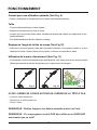
FONCTIONNEMENT
Conseil pour une utilisation optimale (Voir Fig. 9)
Taille
%
{
'
plantes délicates.
#
Réglage de l’angle de la tête de coupe (Voir Fig.10)
`
relâchant le bouton. Quand l’arbre est en position, le bouton se verrouille en place.
Utilisation de la pièce d’écartement (Voir Fig. 11)
#
'
?
Fig. 9
Fig. 10
Fig. 11
ISI DE L’HERBE SE COINCE AUTOUR DE l’ARBRE DE LA TÊTE À FILS:
*
+
@
REMARQUE : Retirez toujours les débris enroulés autour de l'axe.
REMARQUE : Ce coupe-gazon ne doit PAS être utilisé avec QUELQUE
accessoire que ce soit!!
32
FONCTIONNEMENT
AVANCER LES FILS
REMARQUE: La débroussailleuse est équipée d’une tête d’alimentation
automatique.
Ne cognez pas la tête afin d’essayer d’avancer la ligne : cela endommagerait
la débroussailleuse et annulerait la garantie.
\
REMARQUE: Les fils s'étendront d'environ 3/16 de pouce (env. 0,5 cm)
à chaque relâchement et pression de la gâchette de l’interrupteur,
jusqu'à ce qu'ils atteignent la longueur de la lame du déflecteur d’herbe.
Ne coupez pas l'herbe lorsqu'elle est mouillée. Les meilleurs résultats
sont obtenus sur de l'herbe sèche.
REMARQUE : Il peut y avoir besoin de 10 démarrages et redémarrages
avant que la ligne n'avance complètement et fonctionne correctement.
REMARQUE: Ne déplacez pas le coupe-herbe dans l'herbe jusqu'à ce
que le bouton est enfoncé, c'est à dire attendre que la débroussailleuse
est en marche.
\
{
(voir Fig. 12 et Fig. 13).
J
(voir Fig. 14).
Fig. 12
Fig. 13
33
Fig. 14
MAINTENANCE
minimale. Le fonctionnement continu satisfaisant dépend du bon entretien et du nettoyage régulier
de l’outil
AVERTISSEMENT
Avant d’effectuer toute maintenance, éteignez et débranchez l’outil.
"
d’une brosse douce ou d’un chiffon sec.
"
douce ou d’un chiffon sec.
?
sous la protection.
Fixation d’une nouvelle bobine de ligne de coupe (Voir Fig. 15 et Fig. 16)
+
[
① Appuyez sur les onglets pouce et retirez le couvercle de la bobine
③ Retirez la bobine vide
② Du carter
④ Du couvercle de la bobine.
@
\
{
'
+
⑤. La ligne doit dépasser d’env. 4 pouces du couvercle de la bobine.
+
dépasser d’env. 4 pouces du coin de la bobine.
*
① sur le couvercle de la bobine avec les fentes ④ dans le carter.
\
'
ķ
ĸ
Ĺ
ĺ
Ļ
ķ
ĸ
Fig. 15
Fig. 16
Ĺ
ĺ
Ļ
34
MAINTENANCE
AVERTISSEMENT
Si les lignes de coupe dépassent les lames de taille, coupez-les afin qu’elles
atteignent juste la lame.
Enroulez une nouvelle ligne sur une bobine (Voir Fig. 17 - Fig. 19)
?
+
@
{
@
`⑥
⑦ dans la partie supérieure
de la bobine comme indiqué
*
{
ligne proprement et par couches. Ne la croisez pas.
⑥
⑦ dans la partie supérieure de la bobine
comme indiqué
Finissez d’enrouler, procédez comme décrit ci-dessus pour placer la bobine sur la débroussailleuse.
N’oubliez pas de libérer la ligne de coupe de la fente de blocage.
?
[
"@#
ļ
Ľ
Fig. 17
Fig. 18
Fig. 19
AVERTISSEMENT
Utilisez uniquement le type de ligne de coupe approprié.
Des morceaux projetés depuis la ligne de coupe peuvent causer des blessures
corporelles.
35
DÉPANNAGE
Si votre débroussailleuse semble ne pas fonctionner correctement, suivez
les instructions ci-dessous.
Si ce manuel ne suffit pas à la résolution de vos problèmes, veuillez
appeler le 1-866-384-8432
AVERTISSEMENT
Avant d’effectuer toute maintenance, veuillez vous assurer que l’unité est
débranchée de la source d’alimentation.
L'appareil ne fonctionne pas
{
#
{
{
L’outil fonctionne lentement
"
{
`
#
le cas, coupez-la afin qu’elle atteigne juste la lame de taille de ligne.
L’alimentation de ligne automatique ne fonctionne pas.
[
'
`#
de ligne de coupe sur la bobine, installez une nouvelle bobine de ligne de coupe comme indiqué ci
-dessus.
*
\
'
#
{
'
#
qui suit :
"
@
@
{
décrit ci-dessus. Remplacez la bobine comme indiqué.
Mise au rebut et recyclage
cycle des matières premières.
+
36
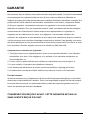
GARANTIE
"
¡
est accompagné d’une garantie limitée de deux (2) ans contre les défauts de fabrication et
#
de 30 jours s’applique. Les batteries comportent une garantie d’un an contre les défauts de
\
conformément aux instructions du mode d’emploi et aux réglementations. La garantie ne
accidents, des réparations ou des altérations et d’un manque de maintenance directs ou indirects.
\
\
`{`
Composants non couverts par la garantie :
1. Toute pièce devenue non opérationnelle en raison d’une mauvaise utilisation, d’une utilisation
commerciale, d’un abus, d’une négligence, d’un accident, d’une mauvaise maintenance ou
d’une modification; ou
2. L’unité, si elle n’a pas été utilisée et/ou maintenue conformément au mode d’emploi; ou
{
4. Les éléments de maintenance de routine comme les lubrifiants, l’aiguisage de la lame;
5. La détérioration normale de la finition extérieure en raison de l’usure ou de l’exposition.
Frais de transport :
les frais de transport pour le déplacement de toute unité d’équipement énergétique ou de fixation
relèvent de la responsabilité de l’acheteur. Celui-ci est responsable de payer les frais de transport
[
CONSERVEZ VOS REÇUS D’ACHAT. CETTE GARANTIE EST NULLE
SANS LESDITS REÇUS D’ACHAT.
37
VUE EXPLOSÉE
GT1415 VUE EXPLOSÉE
38
LISTE DES PIÈCES
LISTE DES PIÈCES GT1415
NUMÉRO D'ARTICLE
DESCRIPTION
QTÉ.
1
GT70RM.10.00
PIÈCE N°
Ensemble moteur
1
2
GT70FM.A0.01
Ensemble habitacle moteur droit
1
3
$=¢¢ £
Ressort de pression
1
4
GT72RM.20.00
Ensemble axe télescopique supérieur
1
5
GT72RM.20.40
1
6
GT72RM.30.00
Ensemble axe inférieur
1
7
%$+¢
Système de verrouillage de bobine de rechange
1
8
GT70RM.40.00
Connecteur de sortie
1
9
GT72RM.50.00
Ensemble protection contre les débris
1
10
GT70RM.70.00
1
11
GT01FM.31.00
Bobine (pièce de rechange # RS0101)
1
12
GT72RM.00.08
Protection des fleurs
1
13
GT70FM.A0.02
Ensemble habitacle moteur gauche
1
14
$¤>¥*
Ensemble plaque impactée
1
15
GT01FM.10.00
Ensemble poignée auxiliaire
1
16
!$+¤ Interrupteur
1
17
GT70RM.A0.09
%
1
18
GT70RM.00.08
Clé hexagonale
1
19
$+¤`
Ensemble cordon d’alimentation
1
39
NOTES
40
CONTENIDO
Contenido
41
Especificaciones Del Producto
41
Normas Generales De Seguridad
42-44
Información Eléctrica
44-47
SÍMBOLOS
47-48
Conozca A Su Desbrozadora De Cable
49
Armado
50-51
Funcionamiento
52-53
Mantenimiento
54-55
Solución De Problemas
56
Garantía
57
Despiece
58
Lista De Piezas
59
Notas
60
ESPECIFICACIONES DEL PRODUCTO
BORDEADORA DE CABLE DOBLE DE 14"
Voltaje
120 V ~ 60 Hz
Amperaje
7 Amp
Revoluciones por minuto
7000 rpm
Diámetro del cable
0,065 pulgadas (1,65 mm)
Ancho de corte
14 pulgadas
Peso
3 kg (7,1 libras)
41
NORMAS GENERALES DE SEGURIDAD
ADVERTENCIA
Debe seguir las normas de seguridad cuando utilice la desbrozadora de hierba.
Para su propia seguridad y la de personas cercanas por favor lea estas instrucciones
antes de utilizar la desbrozadora.
No utilice la desbrozadora sin leer antes la hoja de instrucciones. Por favor, guarde las instrucciones
de manera segura para su uso posterior.
¦§
¨
los bordes de hierba en jardines privados y de hobby que no son accesibles con una podadora.
¦
'©
a los lados de las carreteras, así como en la agricultura y la silvicultura.
¦
riesgo de lesiones.
- Setos, arbustos y matas,
- Flores,
- En términos de compostaje.
¦§
§
capacidades físicas, sensoriales o mentales reducidas, o falta de experiencia y conocimiento, a
menos que una persona responsable de su seguridad les supervise o les instruya en el uso del
aparato.
#§'
#§
¨
personas calificadas con el fin de evitar un peligro.
?
"
§
+'
§
?
¨
¨
*
§
§
"
§
Mantenga las manos y los pies alejados de los medios de corte en todo momento y especialmente
al encender el motor.
ª
ª
filamento. Después de extender la línea de corte nueva devuelva siempre la desbrozadora a su
posición normal de funcionamiento antes de encenderla.
"
¦
42
NORMAS GENERALES DE SEGURIDAD
"
¦
Nunca utilice piezas de repuesto o accesorios no suministrados o recomendados por el fabricante.
+
¨
'
cuando no esté en uso.
*©
¨
NSTRUCCIONES DE SEGURIDAD ADICIONALES PARA SU DESBROZADORA
"
?
¨
'
'
'
"
¦
ª
*
'
«¦
¦
¨
"
'
ª
[
esté en condiciones seguras de funcionamiento.
\
'
de la protección.
MANTENIMIENTO
¦
¨§
¦§
©
?
Preparación para el uso, operación y mantenimiento de la herramienta:
- Lea las instrucciones cuidadosamente;
- Familiarícese con los controles y el uso adecuado del equipo;
{*
¨
¨§
§'
{#§
¨
NO TOQUE EL CABLE ANTES DE DESCONECTAR LA ENERGÍA;
{"
¦§
desgastados.
43
NORMAS GENERALES DE SEGURIDAD
ADVERTENCIA
- Los elementos de corte siguen girando después de apagar el motor;
- Mantenga las extensiones lejos de elementos de corte;
- Se recomienda que los aparatos deben ser potenciados a través de un
dispositivo de corriente residual (DCR) con una corriente de disparo de no
más de 30 mA.
- El equipo no debe usarse para compostaje (triturado) ya que ésto
puede causar lesiones o daños a la propiedad.
INFORMACIÓN ELÉCTRICA
ADVERTENCIA
PARA EVITAR PELIGROS ELÉCTRICOS, DE FUEGO O DAÑOS A LA
HERRAMIENTA, UTILICE LA PROTECCIÓN DE CIRCUITO APROPIADA.
SU DESBROZADORA DE CÉSPED ESTÁ CABLEADA DE FÁBRICA PARA
FUNCIONAR A 120 V. CONÉCTELA A UN CIRCUITO DE 120 V, 15 A, Y USE
UN FUSIBLE DE 15 A CON RETARDO O UN INTERRUPTOR DE CIRCUITO.
PARA EVITAR DESCARGAS ELÉCTRICAS O INCENDIO, SI EL CABLE DE
EXTENSIÓN ESTÁ DESGASTADO, CORTADO O DAÑADO DE CUALQUIER
FORMA, CÁMBIELO INMEDIATAMENTE.
DOBLE AISLAMIENTO
Esta desbrozadora tiene un enchufe que se parece al que se muestra en la Fig. A
La desbrozadora tiene doble aislamiento para ofrecer un doble espesor de aislamiento entre usted
¦
¦
componentes internos del motor de metal con aislamiento de protección.
44
INFORMACIÓN ELÉCTRICA
Fig. A
ADVERTENCIA
USE SOLAMENTE PIEZAS DE REPUESTO IDÉNTICAS AL REPARAR LA
DESBROZADORA, PARA EVITAR LESIONES.
ADVERTENCIA
EL DOBLE AISLAMIENTO NO TOMA EL LUGAR DE LAS MEDIDAS DE
SEGURIDAD NORMALES AL USAR ESTA DESBROZADORA
ADVERTENCIA
PARA EVITAR LA ELECTROCUCIÓN:
1. Utilice sólo piezas de repuesto idénticas cuando le da servicio a una
herramienta con doble aislamiento. El mantenimiento debe ser realizado
por un técnico calificado.
2. No la use en áreas húmedas o mojadas o expuestas a la lluvia.
INSTRUCCIONES DE CONEXIÓN A TIERRA
"*#$+?"[*J?"$"*["$$*@¬*
resistencia para la corriente eléctrica y reduce el riesgo de descarga eléctrica. Esta herramienta
está equipada con un enchufe POLARIZADO. El enchufe DEBE estar conectado a un cable de
extensión a tierra correspondiente de acuerdo con todos los códigos y ordenanzas locales.
"$[$+J¤?"=?J¤?##?["#@*#
¨
línea a tierra, haga que un electricista calificado instale una salida adecuada.
45
INFORMACIÓN ELÉCTRICA
PRECAUCIÓN
ASEGÚRESE SIEMPRE DE QUE SU TOMACORRIENTE TENGA LA LÍNEA
A TIERRA CORRECTA. SI NO ESTÁ SEGURO, HÁGALO REVISAR POR UN
ELECTRICISTA CERTIFICADO.
ADVERTENCIA
ESTA DESBROZADORA ES SÓLO PARA USO EXTERIOR.
NO LA EXPONGA A LA LLUVIA NI LA USE EN LUGARES HÚMEDOS.
NORMAS PARA EL USO DE CABLES DE EXTENSIÓN
?*%+¥"#"*+?*+$*©
¨
¨©
?
provocará el sobrecalentamiento. La siguiente tabla muestra el calibre correcto a utilizar en función
de longitud del cable y la clasificación en amperios de la placa de identificación. En caso de duda,
¦
©¦¦
el cable.
Calibre mínimo para cables de extensión (AWG)
(cuando se usa 120 V solamente)
Amperaje
Longitud total del cable en pies (metros)
Mayor que
No mayor que
25’ (7.6 m)
0
6
18
16
16
14
6
10
18
16
14
12
10
12
16
16
14
12
12
16
14
12
No se recomienda
50’ (15 m) 100’ (30.4 m) 150’ (45.7 m)
*©
¨
#
¨§¦
antes de su uso. Mantenga las extensiones lejos de objetos cortantes, calor excesivo y áreas
©'
46
INFORMACIÓN ELÉCTRICA
?
de al menos calibre 12 y debe estar protegido con un fusible de 15 A con retardo de tiempo. Antes
ª
¨©
¦¨
de apagado y la corriente eléctrica es idéntica a la impresa en la placa del motor.
'¦'§¦
ADVERTENCIA
AUNQUE ESTA DESBROZADORA TIENE DOBLE AISLAMIENTO, EL
CABLE DE EXTENSIÓN Y EL TOMACORRIENTE DEBEN PONERSE A
TIERRA MIENTRAS ESTÁ EN USO PARA PROTEGER AL OPERADOR DE
UNA DESCARGA ELÉCTRICA.
SÍMBOLOS
Explicación de los indicadores de advertencia de la máquina.
A
B
C
D
E
F
G
A : ¡Advertencia!
B : Lea el manual de instrucciones antes de comenzar.
C|?
¨
ª
D : No exponer a la lluvia.
E|+
§
#§
¨
¡NO TOQUE EL CABLE ANTES DE DESCONECTARLO DE LA ALIMENTACIÓN!
F : Mantenga a las demás personas fuera de la zona de peligro.
G : Advertencia. Los elementos cortantes siguen girando después de que el motor se detiene.
47
SÍMBOLOS
*ª
ª
\
©
aprenda su significado. La interpretación adecuada de estos símbolos le permitirá operar este
producto de una manera mejor y más segura.
SÍMBOLO
NOMBRE
DESIGNACIÓN/EXPLICACIÓN
V
Voltios
Voltaje
A
Amperios
Corriente
Hz
Hertz
Frecuencia (ciclos por segundo)
W
Vatios
Energía
Minutos
Corriente alterna
Corriente directa
ª
Construcción Clase II
Construcción de doble aislamiento
Velocidad al vacío
Velocidad racional, sin carga
Por minuto
Revoluciones, carreras, velocidad de superficie,
órbitas, etc., por minuto
Alerta por condiciones
de humedad
No exponer a la lluvia ni usar en lugares anegados
Lea el Manual del Operario
Para reducir el riesgo de lesión, el usuario debe
leer y entender el manual del operario antes de
usar este producto.
Protección ocular
?
¨
Alerta de Seguridad
Precauciones que involucran su seguridad.
Cabello largo
No mantener el cabello largo alejado de la entrada
de aire puede causar lesión personal.
Ropa suelta
No evitar que la ropa suelta sea succionada por la
entrada de aire puede causar lesión personal.
Mantenga las personas
alejadas
Mantenga a todas las personal al menos a 50 pies
de distancia.
min
no
/min
48
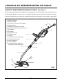
CONOZCA SU DESBROZADORA DE CABLE
CONOZCA SUS DESBROZADORA DE CABLE (Ver Fig. 1)
El uso seguro de este producto requiere una comprensión de la información sobre el producto y en
el manual del operador, así como un conocimiento del proyecto que se intenta. Antes de usar este
producto, familiarícese con todas las características de funcionamiento y las normas de seguridad.
1. Cable de energía
2. Manija superior
3. Interruptor de Encendido/Apagado
4. Manija auxiliar
5. Acoplador de liberación rápida
6. Seguro para ajustar la altura del eje
7. Eje superior
8. Eje inferior
9. Acoplador del eje
4
10. Guía del borde
11. Carrete
12. Protección contra sedimento
6
13. Contenedor del cable
14. Llave hexagonal
15. Cable podador
16. Atornillador para montar la
protección contra sedimento
1
14
2
3
13
7
5
9
8
16
10
12
15
Fig.1
11
49
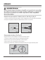
ARMADO
ADVERTENCIA
Antes del montaje, asegúrese de que la desbrozadora esté apagada y
desenchufada.
Montaje de la guarda de protección (Ver Fig. 2 y Fig. 3)
1. Coloque la protección en el cabe al del motor, tal como se indica.
2. Asegure la protección con un tornillo y la llave hexagonal.
Fig. 2
Fig. 3
ADVERTENCIA
No utilice nunca la desbrozadora a menos que la guarda esté colocada
correctamente.
Montaje de la empuñadura secundaria (Ver Fig. 4 y Fig. 5)
§
*'
§¨¦¨?
ª
\
§§
4. Atornille la tuerca en el otro lado del perno. No apriete demasiado el tornillo.
Fig. 4
Fig. 5
50
ARMADO
ADVERTENCIA
Nunca intente bloquear la palanca del gatillo en la posición de encendido.
Si el cable de energía de este equipo se daña, el fabricante, su agente de
post venta o un personal con similar capacitación debe reemplazarlo
para evitar peligros.
Conecte los ejes superior e inferior entre sí (Ver Fig. 6 y Fig. 7)
1. \
*©
2. Presione el acoplador de liberación rápida hasta que calce en su posición.
Fig. 6
Fig. 7
Cómo ajustar la altura (Ver Fig. 8)
Al ajustar la altura, puede establecer su posición de trabajo optima.
1. Presione el seguro de ajuste del eje y manténgalo presionado.
2. Mueva el eje a una de las tres posiciones y suele el seguro.
3. GIre el eje en 180° a la izquierda y suelte el seguro.
4. Mueva el eje hacia atrás y adelante para asegurarse de que el seguro esté bien puesto.
Fig. 8
51
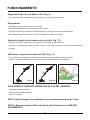
FUNCIONAMIENTO
Sugerencia para el uso óptimo (Ver Fig. 9)
¨
¨
Desbrozado
#
[
*
'
''
#
Ajuste del ángulo de la cabeza de corte (Ver Fig. 10)
\
¨'¨¦''¦
posición 4, mientras que suelta el botón. Cuando el eje esté en posición, el botón se bloqueará en
su lugar.
Utilizando el soporte de distancia (Ver Fig. 11)
#
'
'
?
'
Fig. 9
Fig. 10
Fig. 11
SI SE QUEDA ATRAPADO CÉSPED EN EL EJE DEL CABEZAL:
+
+
¤
NOTA: Quite siempre los sedimentos que puedan enredarse en el eje.
NOTA: ¡Esta bordeadora NO está hecha para funcionar con NINGÚN
ADITAMENTO!
52
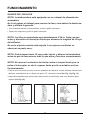
FUNCIONAMIENTO
AVANCE DE LOS HILOS
NOTA: la desbrozadora está equipada con un cabezal de alimentación
automática.
No le dé golpes al cabezal para avanzar la línea, esto dañará la desbrozadora y anulará la garantía.
NOTA: los hilos se extenderán aproximadamente 3/16 in. Cada vez que
active y desactive el interruptor hasta que alcancen la longitud de la hoja
del deflector.
No corte el pasto cuando esté mojado. Los mejores resultados se
observan en pasto seco.
NOTA: Podría tomar hasta 10 veces más iniciar y detener la bordeadora
antes de que la línea avance todo lo que debe y funcione correctamente.
NOTA: No mueva la cortadora de hierba contra el césped hasta que se
pulsa el interruptor, es decir, esperar hasta que la recortadora esté en
funcionamiento.
\¨
adelante, sosteniéndolo en un ángulo de aprox. 30 ° mientras lo hace (Ver Fig. 12 y Fig. 13).
=
¦
superior (Ver Fig. 14).
Fig. 12
Fig. 13
53
Fig. 14
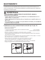
MANTENIMIENTO
#
§
ª
mínimo de mantenimiento. El funcionamiento satisfactorio continuado depende del cuidado de la
herramienta y la limpieza regular.
ADVERTENCIA
Antes de realizar cualquier trabajo de mantenimiento, apague y
desenchufe la herramienta.
¨
§
ª
§
?
la parte de abajo de la guarda.
Instalación de un nuevo carrete de línea de corte (Ver fig. 15 y fig. 16)
+
[
§
① \
§
② De la carcasa
③ Quiteel carrete vacío
④ De la cubierta del carrete.
©
>
poco hasta que se asiente.
#
ª
ªª'⑤ La línea
debe sobresalir aprox. 4 pulgadas de la cubierta del carrete.
#
ª
ªª
'⑤.
La línea debe sobresalir aprox. 4 pulgadas de la esquina del carrete.
*
§① en la cubierta del carrete con los cortes ④ en la carcasa.
'
'
ķ
ĸ
Ĺ
ĺ
Ļ
ķ
ĸ
Fig. 15
Fig. 16
Ĺ
ĺ
Ļ
54
MANTENIMIENTO
ADVERTENCIA
Si las líneas de corte sobresalen más allá de la cuchilla de corte, córtelas
para que lleguen justo hasta la hoja.
Envolviendo línea nueva en un carrete (Ver fig. 17 - Fig. 19)
?
¨ª
±
\ª
ª
=
ª
@
ª
¨
ª
\
ª
`ª
⑥ a los dos ojales ⑦ en la parte
superior del carrete como se muestra.
ª
¨*©ª
en forma ordenada y en capas. No la envuelva en zigzag.
ª
⑥ a los dos ojales ⑦ en la parte superior del carrete como se muestra
¨
'
desbrozadora. No olvide quitar la línea de corte de la ranura de parqueo.
?
[
²@#
ļ
Ľ
Fig. 17
Fig. 18
Fig. 19
ADVERTENCIA
Utilice sólo el tipo apropiado de la línea de corte.
Trozos del cable de corte podrían causar lesiones al salir volando.
55
SOLUCIÓN DE PROBLEMAS
Si su desbrozadora parece no funcionar correctamente, siga las
instrucciones a continuación.
Si esto no resuelve el problema, llame al 1-866-384-8432
ADVERTENCIA
Antes de realizar cualquier mantenimiento, por favor asegúrese de que la
unidad esté desconectada de la fuente de alimentación.
La máquina no funciona
ª
#¦
¨
ª¨
de post venta especificada.
La herramienta funciona lentamente
Limpie cuidadosamente si es necesario
ª
¦
ª
`
del carrete. Si lo hace, corte de forma que sólo llegue hasta la hoja de corte de la línea.
La alimentación automática de línea no funciona.
[
§
ª
ª
`
Si la línea de corte que queda en el carrete no es suficiente, instale un carrete de línea de corte
nuevo como se indica más arriba.
*
§
'
'#ª
sobresale más allá de la cuchilla de corte, córtela para que llegue justo hasta la hoja.
#
¨
¦
ª
ª
¦
siguiente sugerencia:
@
@
ª
¨
¨
©
Eliminación y reciclaje
\
§
¦
material sin mayor procesamiento, por lo que se puede reutilizar o devolver al sistema de materias
primas.
¦
plástico. Los componentes defectuosos deben eliminarse como residuos especiales. Pregunte a
su concesionario o autoridad local.
56
GARANTÍA
Estamos orgullosos de fabricar un producto de alta calidad y duradero. Este producto
¡
ª
§
¨
materiales a partir de la fecha de compra bajo uso doméstico normal. Si el producto se va a utilizar
para uso comercial, industrial o de alquiler, regirá una garantía limitada de 30 días. Las baterías
ª§
¨
ª
cargarse de acuerdo con las instrucciones y normas del manual del operador con el fin de ser
válida. La garantía no se aplica a los defectos debido al abuso directo o indirecto, negligencia, mal
uso, accidentes, reparaciones o modificaciones y la falta de mantenimiento. Por favor guarde su
recibo / lista de empaque como prueba de compra. Esta garantía le otorga derechos legales
específicos, y usted puede tener otros derechos que varían de estado a estado. Para servicio al
producto llame a Servicio al cliente al (866) 384-8432.
Artículos no cubiertos por la garantía:
1. Cualquier parte que se haya vuelto inoperante debido al mal uso, uso comercial, abuso,
negligencia, accidente, mantenimiento inadecuado, o modificación, o
2. La unidad, si no ha sido operada y / o mantenida de acuerdo con el manual del propietario, o
3. El desgaste normal, excepto como se indica a continuación;
4. Los elementos de mantenimiento rutinario tales como lubricantes, afilado de cuchillas;
5. El deterioro normal del acabado exterior debido al uso o la exposición.
Cargos de transporte:
Los gastos de transporte para el movimiento de cualquier unidad de equipo eléctrico o accesorio,
son responsabilidad del comprador. Es responsabilidad del comprador pagar los gastos de
transporte para cualquier parte enviada para sustitución bajo esta garantía a menos que dicha
¨
[
GUARDE SUS RECIBOS. ESTA GARANTÍA QUEDA ANULADA SIN ELLOS.
57
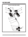
DESPIECE
GT1415 DESPIECE
58
LISTA DE PIEZAS
GT1415 LISTA DE PIEZAS
N° DE ARTÍCULO
DESCRIPCIÓN
CANT.
1
>£@[
N° DE PIEZA
Ensamblaje del motor
1
2
>£J[*
Ensamblaje de la carcasa de lado derecho del motor
1
3
$=¢¢ £
Resorte presionado
1
4
>£@[
Ensamblaje del eje telescópico superior
1
5
>£@[`
Acoplador del eje
1
6
>£@[
Ensamblaje del eje inferior
1
7
%$+¢
Seguro de repuesto para el carrete
1
8
>£@[`
Conector de salida
1
9
>£@[
Ensamblaje del protector contra sedimento
1
10
>£@[£
Cabezal del carrete
1
11
>J[
²@#
1
12
>£@[
Protector para flores
1
13
>£J[*
Ensamblaje de la carcasa del lado izquierdo del motor
1
14
$¤>¥*
Placa de impacto
1
15
>J[
Ensamblaje de la manija auxiliar
1
16
WODQ10.03.06
Interruptor
1
17
>£@[*
Interruptor de encendido
1
18
>£@[
Llave hexagonal
1
19
$+¤`
Cable de energía
1
59
NOTAS
60