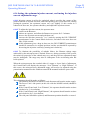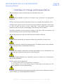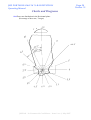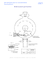
1
JME PORTABLE 6 MeV M X-RAY BETATRON
Operating Manual
Page 1
Section 1
LTD.
ADVANCED INSPECTION SYSTEMS
JME Portable 6 MeV
X-RAY BETATRON
Microprocessor model:
PXB-6 M
For Radiographic Non Destructive Testing
Operating Manual
This is an uncontrolled document
No amendments will be issued
JME Ltd - In Commercial Confidence - Issue 1 rev 1, May 2007
JME PORTABLE 6 MeV M X-RAY BETATRON
Operating Manual
Contents
1
1.1
Safety Precautions
Radiation Safety
1.2
1.3
1.4
1.5
Electrical safety
Physical protection
Laser safety precautions
Other precautions
2
2.1
3
3.1
Introduction
Basic Description
Equipment Modules and Components
System components
4
Assembly and Installation
5
Requirements Before Use
6
Preparation for operation
Error Messages
Setting optimum injection current
Replacement of HV injection unit
6.15
6.16
6.17
7
Instructions for X-raying
8
Technical Maintenance
9
Guidelines for Storage and Transportation
10
10.1
10.2
10.3
10.4
Charts and Diagrams
Dose rate distribution (vertical plane)
Dose rate distribution (horizontal plane)
Exposure chart for steel
Exposure chart for concrete
11.1
Technical Specification
Betatron focal spot location
11
12
Disclaimer
JME Ltd - In Commercial Confidence - Issue 1 rev 1, May 2007
Page 2
Section 1
JME PORTABLE 6 MeV M X-RAY BETATRON
Operating Manual
Page 3
Section 1
The following symbols are used throughout this manual to indicate
where special safety precautions must be observed.
THIS SYMBOL MEANS 'BE ALERT'
YOUR SAFETY IS INVOLVED, EXERCISE
GREAT CARE AND FOLLOW THE ADVICE
GIVEN TO AVOID POTENTIALLY HAZARDOUS
SITUATIONS.
THIS SYMBOL MEANS 'ELECTRICAL
HAZARD'
OBSERVE INSTRUCTIONS.
THE PXB-6 M WORKS WITH POTENTIALLY
DANGEROUS VOLTAGES. UNDER NO
CIRCUMSTANCES SHOULD ANY
UNAUTHORISED PERSON ATTEMPT TO
REMOVE ANY OF THE EQUIPMENT COVERS
TO CARRY OUT MAINTENANCE OR REPAIR.
THE PXB-6 M IS TO BE RETURNED TO JME LTD
AS THE AUTHORISED SERVICE COMPANY.
THIS SYMBOL MEANS 'RADIATION
HAZARD'.
YOUR SAFETY AND THAT OF OTHERS IS
INVOLVED. THE PXB-6M IS ONLY TO BE
OPERATED BY AUTHORISED RADIATION
WORKERS, IN ACCORDANCE WITH YOUR
COMPANY GUIDELINES.
THIS SYMBOL MEANS 'LASER HAZARD'.
PLEASE REFER TO INSTRUCTIONS AND
SAFETY INFORMATION IN SECTION 1.18.
See also section 5, Safety Requirements before use.
JME Ltd - In Commercial Confidence - Issue 1 rev 1, May 2007
JME PORTABLE 6 MeV M X-RAY BETATRON
Operating Manual
Page 4
Section 1
RADIATION SAFETY WARNING
THIS EQUIPMENT SHALL ONLY BE USED BY QUALIFIED INDUSTRIAL
RADIOGRAPHERS WHO HAVE HAD TRAINING IN ITS SAFE USE.
JME Ltd. PXB-6 portable x-ray Betatron systems emit high levels of x-ray radiation
during radiographic exposure sequences.
An energized Betatron at close range can cause serious injury, sickness, or possibly
death to anyone who is exposed to it unintentionally.
A Betatrons x-ray accelerator containing the x-ray tube must NOT be touched by
hand under any circumstances whenever energized.
Since x-ray and gamma radiation cannot be detected by the normal human senses,
strict procedures must be followed and proper use made of radiation survey meters to
avoid and prevent dangerous levels of exposure. It is recommended that a suitable
calibrated survey meter is used to establish safe boundary conditions for a given set of
operating conditions (pipe wall thickness / MeV setting etc). This should be done by
approaching from a known safe distance towards the radiation area whilst using the
survey meter. Never assume an area or the pipeline is safe after a timed radiographic
exposure, always perform a survey to ensure the x-ray accelerator has de-energized, to
comply with federal and provincial regulations.
All work-site radiographers should use an audible alarm rate meters set to alarm at 5
mSv/hr (500 mR/hr) as an additional safety precaution.
It is very important and required by regulations to prevent access by unauthorized
persons to the betatrons control units and the keys which allow them to be activated.
The systems must be operated only by properly trained, qualified radiographers, who
have read and understand the requirements of this Operator’s Manual, or by trained
assistants working under their direct supervision.
In Canada it is mandatory to have an audio visual alarm system. A JME audio / visual
alarm is provided as part of the system and must be used. In other countries it is
provided as an optional accessory with the advice that it is recommended as a safety
feature. The alarm comes with an instruction manual which should be read and be
freely available to all personnel likely to be near the radiation controlled area, before
using the Betatron.
JME Ltd - In Commercial Confidence - Issue 1 rev 1, May 2007
JME PORTABLE 6 MeV M X-RAY BETATRON
Operating Manual
Page 5
Section 1
Safety Precautions
THIS EQUIPMENT SHALL ONLY BE USED BY
QUALIFIED PERSONNEL WHO HAVE HAD TRAINING IN ITS
SAFE USE.
1.1 Radiation Safety
1.1.0 An energized x-ray tube in the Betatron can cause serious injury, sickness, or
possibly death to anyone who is exposed to it unintentionally.
1.1.1 The JME PXB-6 M Portable X-Ray Betatron is designed to produce high energy
ionising radiation for industrial radiographic non-destructive testing. Because such
radiation is potentially harmful to living tissue, no attempt should be made to use or
operate the Betatron unless, and until, appropriate safety precautions have been taken
to ensure no possible danger to personnel.
1.1.2 Radiation can only be emitted when the three major modules, Accelerator,
Power Unit and Control Panel, have been properly interconnected, supplied with
external electrical power, and the safety interlock circuit is correctly enabled.
Otherwise the Betatron is completely inert and cannot emit X-Rays.
1.1.3 X-rays cannot be produced while the Safety key on the front of the Control
Panel is removed or in the DISABLE position, thereby disabling the electron
injection circuit.
1.1.4 The Betatron may only be operated in accordance with applicable Ionising
Radiation and Public Health Regulations, and by competent and experienced
personnel who ensure that nobody could become inadvertently exposed to radiation
levels in excess of prescribed limits.
JME Ltd - In Commercial Confidence - Issue 1 rev 1, May 2007
JME PORTABLE 6 MeV M X-RAY BETATRON
Operating Manual
Page 6
Section 1
1.1.5 When the Betatron is not in use, both the MAINS key (on the power Unit) and
the X-Ray Enable key (on the Control Panel) must be removed and placed in secure
storage under the control of a designated competent person. The manufacturer cannot
accept any responsibility for the consequences of non-compliance with appropriate or
recommended procedures.
1.1.6 Since x-ray radiation cannot be detected by the normal human senses, strict
procedures must be followed and proper use made of radiation survey meters to avoid
and prevent dangerous levels of exposure. It is recommended that a suitable calibrated
survey meter is used to establish safe boundary conditions for a given set of operating
conditions. This should be done by approaching from a safe distance towards the
radiation area whilst using a survey meter. Never assume an area is safe after timed
radiographic exposure, always perform a survey to ensure the x-ray generator has de
energized, to comply with federal and provincial regulations.
It is very important and required by regulations to prevent access by unauthorised
persons to the control units and the keys which allow them to be activated.
The systems must be operated only by properly trained, qualified operators, who have
read and understand the requirements of this operator’s manual, or by trained
assistants working under direct supervision.
1.1.7 A Betatron containing the x-ray source must NOT be touched by hand under
any circumstances whenever energised.
1.1.8 JME Ltd. PXB Portable Betatron systems emit high levels of x-ray radiation
during exposure sequences.
JME Ltd - In Commercial Confidence - Issue 1 rev 1, May 2007
JME PORTABLE 6 MeV M X-RAY BETATRON
Operating Manual
Page 7
Section 1
1.2 Electrical Safety
1.2.1 Some Betatron circuits contain voltages in excess of 1 kV, and contain
potentially dangerous components, such as large capacitors which could retain a
charge for several hours after switching off.
For safety reasons, and to avoid the possibility of inadvertent component damage,
outer casings of modules should therefore NOT be removed, except by fully trained,
experienced and authorised service engineers.
1.2.2 To avoid damage to conductor wires and termination's, interconnection cables
should always be treated carefully. They must not be twisted, knotted, crossed by
vehicles, placed over sharp edges or be allowed to hang unsupported. Use supporting
boards and/or rope slings to protect cables in such circumstances.
1.2.3 In particular, ensure that the heavy HT cable between Power Converter and
accelerator is fully uncoiled before use. Where possible, avoid crossing the heavy HT
cable and the thinner signal cable. Where this is not possible, ensure that the cables
cross at 90o.
1.3 Physical Protection
1.3.1 Although strongly constructed of durable materials to withstand normal use at
both indoor and outdoor radiographic inspection sites, the Betatron contains
components which could suffer damage or deterioration if subjected to incorrect
operation, misuse, careless handling or unprotected exposure to adverse
environmental conditions.
1.3.2 All Betatron modules and components should be stored, transported and
operated in reasonably clean and dry conditions. In particular, all equipment should
be protected from ingress by moisture, dirt or extraneous material (without impeding
air circulation to ventilation apertures while the Accelerator and Power Unit are
switched on).
JME Ltd - In Commercial Confidence - Issue 1 rev 1, May 2007
JME PORTABLE 6 MeV M X-RAY BETATRON
Operating Manual
Page 8
Section 1
1.4 Laser safety precautions
1.4.1 The Laser Alignment Device contains a laser diode, lens, and associated driver
circuitry, and is a Class 2 laser product. The output power of the laser diode is
typically 0.8mW, at a wavelength of 635nm, and is set in accordance with British
Standard BS(EN)60825. As such, the laser emits an intense beam of focused red light.
1.4.2 Intense monochromatic light (such as that produced by the Laser Alignment
Device) can present biological hazards. The most vulnerable organ is the eye, as it
will tend to focus the light from the laser directly on the retina. This focusing action
increases the energy density of the beam many times, and can result in damage to the
retina.
DO NOT STARE DIRECTLY AT THE BEAM.
DO NOT ATTEMPT TO VIEW THE BEAM
WITH ANY OPTICAL INSTRUMENTS.
BEWARE OF REFLECTED LASER RADIATION
FROM REFLECTIVE SURFACES
1.4.3 The Laser Alignment Device should be attached to the Betatron Accelerator by
the bracket that is mounted directly over the emission window.
1.4.4 Ensure that no personnel are in a position where their eyes may be exposed to
the laser beam. Keep in mind that the laser beam will be emitted directly out of the
emission aperture, and may be reflected by shiny surfaces.
1.4.5 The device should be switched on using the ON/OFF toggle switch, and the
push-button pressed once. This will enable the laser diode. The beam of red light
indicates the where the X-ray radiation beam will fall when an exposure is initiated.
Adjust the Accelerator and x-ray film to their appropriate position.
1.4.6 The laser has an on-board timer, and will automatically switch off after 60
seconds. To reactivate the beam, press the push-button once more.
1.4.7 When the Accelerator is correctly aligned, the Laser Alignment Device should
be switched off (using the ON/OFF toggle switch), and must be removed from the
Accelerator.
JME Ltd - In Commercial Confidence - Issue 1 rev 1, May 2007
JME PORTABLE 6 MeV M X-RAY BETATRON
Operating Manual
Page 9
Section 1
1.5 Other precautions
1.5.1 When Betatron modules or cables require lifting to a high working position,
place them inside a suitable carrying container with its own lifting attachments.
Slings should only be connected to equipment as shown below. The Accelerator may
be lifted by placing lifting strops around the stepped ends of the case as shown below.
Do not lift from the black positioning end supports. See picture below:
1.5.2 To avoid injury to fingers while carrying the Accelerator, or lifting it into its
storage box, make sure that both adjustment knobs at each end of position stand are
tightened so that no rotation of the accelerator can occur.
1.5.3 Lifting: Note the Accelerator and Power Converter weigh more than can be
safely lifted by one person. Apply appropriate mechanical lifting procedures as
shown below:
JME Ltd - In Commercial Confidence - Issue 1 rev 1, May 2007
JME PORTABLE 6 MeV M X-RAY BETATRON
Operating Manual
Page 10
Section 2
Introduction
2.1 Basic Description
2.1.1 The JME PXB-6 M Portable X-Ray Betatron is a compact system designed to produce the high
energy radiation necessary for radiographic inspection of objects and structures composed of thick
and/or dense materials.
2.1.2 The Betatron system comprises of three principle and three ancillary modules, linked by flexible
interconnecting cables, as follows:
X-ray Accelerator (Radiator):
Detachable positioning
Stand.
X-Ray window & integral dosimeter
Laser alignment unit
Air circulation fans
JME Ltd - In Commercial Confidence - Issue 1 rev 1, May 2007
JME PORTABLE 6 MeV M X-RAY BETATRON
Operating Manual
Page 11
Section 2
Power Unit:
+5v DC
Indicator.
operating time
Counter (hrs)
Mains key
Switch.
Fuses
3.15A (t)
Current trip
Interlock
Posts.
Control Panel:
Emergency stop
Button.
Display LCD
Control buttons
X-ray enable key switch
JME Ltd - In Commercial Confidence - Issue 1 rev 1, May 2007
JME PORTABLE 6 MeV M X-RAY BETATRON
Operating Manual
Page 12
Section 2
Remote Dosimeter
Radiation alarm (Audio/Visual Warning Unit)
Laser Alignment Unit
2.1.3 The Betatron draws electrical power from either a 110 volt or 220 volt nominal single phase AC
mains supply, or an adequately rated portable generator.
2.1.4 Supply frequency is either 50 Hz European Standard, or 60Hz American Standard.
2.1.5 The Power Unit conveys pulses of electrical energy to an electromagnet within the Accelerator
(Radiator), and sends monitoring signals to the Control Panel located safely outside the radiation zone.
2.1.6 The radiation dose accumulated by an X-Ray film or sensor (placed behind the object being
examined) may be measured by the Remote Dosimeter and displayed on the Control Panel. By this
means, exposures may be terminated automatically as soon as the correct pre-set dose has been
received for the particular film/intensifying screen combination being used, and the film density
required.
2.1.7 Audible and visible warning signals are provided by the Audio Visual Warning Unit which must
be used, In addition existing interlock switches and warning devices may be connected directly to the
Interlock socket on the Power Unit or Audio/Visual Unit.
2.1.8 A simple Laser Alignment Device is included, and should be used for setting up
procedures only – it should not be used during normal radiographic procedures. See Laser Safety in
section 2.4.
JME Ltd - In Commercial Confidence - Issue 1 rev 1, May 2007
JME PORTABLE 6 MeV M X-RAY BETATRON
Operating Manual
Page 13
Section 3
Equipment modules and components
3.1 Betatron system components
The PXB-6 M Portable X-Ray Betatron system comprises the following modules, cables and
ancillaries:
X-Ray Accelerator (Radiator) Unit, with integral output dose rate dosimeter, air circulation
fans, detachable positioning stand and laser alignment device.
Power Unit, with integral cooling fans.
Control Panel, with x-ray enable key
Remote (film-side) dosimeter with lead back-scatter shield, for automatic exposure control.
Audio/Visual Warning Unit with integral connecting cable
High voltage cable (Power unit to accelerator) *
Accelerator control cable (Power unit to accelerator) *
Main control cable, mounted on cable reel (Power unit to Control Panel)
Mains cable (Power unit to AC supply) *
Dosimeter cable (Power unit to remote dosimeter)
Spares Kit
Operators manual
1 set of 3 transit cases
* The high-voltage cable, accelerator-control cable, and mains cable carry
dangerous voltages when the system is operational.
JME Ltd - In Commercial Confidence - Issue 1 rev 1, May 2007
JME PORTABLE 6 MeV M X-RAY BETATRON
Operating Manual
Page 14
Section 4
Assembly and Installation
4.0 All Betatron modules are interconnected via flexible cables. The socket that each
cable connects to is clearly marked on the module. See note on previous page about
high voltage cables.
4.1 The Betatron has an earth leakage current of approx 7mA and must be installed by
a qualified electrician to a suitably rated supply.
4.2 Due to the fact that dangerous x-ray radiation is produced when the system is
running, special precautions should be taken to avoid exposing personnel to this
radiation. Where possible, the radiator (or ‘accelerator’) should be deployed in a
specially designed and approved radiography bay, to provide radiation protection.
Where the system is to be used in an ‘on site’ situation, the entire area where
dangerous radiation is present should be clearly marked, and all possible measures to
restrict unauthorized access to that area should be taken.
JME Ltd - In Commercial Confidence - Issue 1 rev 1, May 2007
JME PORTABLE 6 MeV M X-RAY BETATRON
Operating Manual
Page 15
Section 5
Requirements before Use.
5.0 Ensure keys are removed from the control panel and the power unit before
connecting any cables. The operator should keep control of the keys at all times. The
control panel ENABLE key MUST be removed when unattended and after every
exposure. The operator should check that the mains supply to the Betatron is protected
by a suitable RCD.
5.1 The Betatron should only be operated in accordance with national and local rules
and regulations for x-ray sources having a peak photon-energy of 6MeV.
5.2 The operator should be positioned to be as far away as possible from the
accelerator, in the opposite direction to the direction of radiation emission. Also,
adequate protective screens should be employed.
5.3 The diagrams of dose-rate distribution around the radiator in both the horizontal
and vertical planes are shown in diagrams 10.1 and 10.2.
5.4 The thickness of any protective screens will need to be calculated for every
different case, depending on required attenuation, screen material, and position.
5.5 During Betatron operation, adequate ventilation must be provided around the
Accelerator and Power Unit, and any radiographic bay used must be properly
ventilated.
5.6 Before Betatron operation begins, the operator should ensure that there is nobody
in the radiographic bay, or in the designated danger area.
5.7 During Betatron operation, all personnel are prohibited from entering the
radiographic bay, or designated danger area.
JME Ltd - In Commercial Confidence - Issue 1 rev 1, May 2007
JME PORTABLE 6 MeV M X-RAY BETATRON
Operating Manual
Page 16
Section 5
5.8 All staff engaged in Betatron operation and maintenance should have personal
dosimeters.
5.9 The Betatron generates very high voltages during operation. As such, all staff
should be governed by safety requirements for operating and maintaining highvoltage equipment.
See also Section 1 Safety Precautions.
JME Ltd - In Commercial Confidence - Issue 1 rev 1, May 2007
JME PORTABLE 6 MeV M X-RAY BETATRON
Operating Manual
Page 17
Section 6
Preparation for operation
6.1 After the Betatron has been transported and before operation, the units condition
should be verified by a visual inspection.
6.2 The Betatron radiator should be loaded onto a suitable support or manipulating
rig, and all other modules should be connected by the flexible cables. Do not connect
to mains supply at this point.
6.3 Ensure that the circuit breaker and MAINS key switch (found on the power unit)
are set to the OFF position.
6.4 Connect all necessary external interlock circuits to the INTERLOCK binding
posts on either the power unit, or Audio/Visual warning unit. These circuits should
form a closed loop between the interlock posts when all interlocks are in the ‘safe’
position (e.g., doors closed). If additional interlock devices are not to be connected,
the interlock terminals should be connected together using the supplied wire links.
Connect the components together using the cables provided. Ensure that the mains
supply to the Betatron is protected by a suitably rated RCD.
6.5 Ensure that the Emergency Stop push button on the control panel is in the raised
position.
6.6 Connect the remote dosimeter to the power unit (if required). Connect the control
panel to the power unit. Connect the radiator to the power unit. Connect the AV unit
to the power unit (if required).
6.7 Connect the mains cable to a suitable supply, and switch the MAINS key-switch
on. After approximately 3-4 seconds, turn the circuit breaker ON. Then, return to the
control panel, and turn the key-switch to the ENABLE position.
After all these stages have been followed, the Control Panel will illuminate, as will
the power indicator lights on the power unit. Also, all fans within the power unit and
radiator will operate.
After a few seconds, the Control Panel will display the following:
DI
999.9
0.00
RD
DE
T,s
9.99 9999
6.0 0.55
E
I I, A
JME Ltd - In Commercial Confidence - Issue 1 rev 1, May 2007
JME PORTABLE 6 MeV M X-RAY BETATRON
Operating Manual
Page 18
Section 6
6.8 Following transportation, and after following the above switching on procedure,
the operator should check that all of the cooling fans fitted inside the power unit and
radiator are operating correctly. This can be achieved by listening to the units, and by
checking air-flow through their vents.
6.9 If an automatic termination of the exposure is required (once some dose or
exposure time is reached), the operator needs to input the required data using the
keypad. To begin inputting the data, the operator must first ensure that the keypad is
enabled (by turning the safety key to Enable), and then press the parameter selection
button P.
This displays a “<” sign next to the parameter DI. Further presses of the P button
scroll between the DI, DE and T settings. (These symbols refer to Internal Dose,
External Dose, and Time).
Once the “<” sign is next to the parameter that is required to terminate the exposure,
the operator should use the + and – keys to set that required parameter. Momentarily
pressing the + or – button will adjust the parameter by one unit at a time. By holding
the buttons down, the parameter will adjust more quickly.
Please note, that the parameters can only be set while the Betatron is not radiating.
In order for a particular parameter to automatically terminate the exposure, it must he
enabled. To do this, select the appropriate parameter with the P key (although it may
already selected), and then pres SET. The “<” symbol will change to a “↵”. Now,
when the exposure is started, the display will show the preset value every 4 to 5
seconds, and at all other times show the running value.
6.10 If it is necessary to change the electron energy, use the E/R key to select the E
parameter, and adjust it to the desired level. It is not necessary to press the SET key.
Also, the maximum dose rate (rate of output radiation) that the microprocessor will
‘tune’ to, can be set by adjusting the RD parameter. This is also selected by the E/R
button, and adjusted in the same way as the electron energy.
6.11 Press START after completion of all the above set up operations. The
Audio/Visual Warning Unit’s amber light and siren will operate, giving warning of
imminent radiation. This warning will last for 10 seconds, and the Control Panel will
display a countdown like this:
DELAY TIME 10s
0.0
6.0
0.55
After the 10 second delay, the magnet will begin to operate. Also, the amber light and
siren will switch off, and be replaced by a red light – giving warning of radiation on.
JME Ltd - In Commercial Confidence - Issue 1 rev 1, May 2007
JME PORTABLE 6 MeV M X-RAY BETATRON
Operating Manual
Page 19
Section 6
During the first 3 seconds of exposure, the magnet voltage is still increasing, and no
radiation is being produced. Then the microprocessor will begin to ‘search’ for an
optimum set of parameters for Betatron operation. During this time, the output
radiation RD will vary. The time taken to find the optimum settings depends on many
factors – the most important being whether or not the internal ROM is enabled (by
default it is enabled), and whether the Betatron has been recently tuned for it’s current
energy and dose rate settings. If these conditions are true, the searching will take only
2-3 seconds – this will be the mode most frequently observed by the operator.
However, if these conditions are not met, the microprocessor may take up to a minute
to find a new set of optimum parameters. Once the optimum point has been found, the
microprocessor then enters a tracking mode, to maintain the highest output.
It should be noted that the microprocessor may revert back to a course scan of settings
(resulting in a drop in output radiation) if there are great fluctuations in mains power,
or if a different supply voltage is being used.
The microprocessor can also be manual switched back into course scan mode by
holding the SCAN button until the output radiation drops. This may be useful if the
operator is aware that the Betatron can produce greater output than it is currently
producing, but the machine has tuned to a ‘local maximum’.
6.12 Injection current II is controlled by the microprocessor, and is displayed on the
Control Panel. The value of the optimum injection current will have been recorded by
JME Ltd, and should not normally need adjustment. If adjustment is necessary, this is
performed using the INJ CURRENT potentiometer mounted on the Control Panel. If
the adjustment range is insufficient, an error message will be displayed (see section
6.15). After any adjustment to injection current, it is advisable to press the SCAN
button, to commence a new search for optimum settings.
It should be noted that during operation the values of the injection current and the
dose rate may vary, but these variations should not be too great. Great deviations may
indicate that a fault has developed.
6.13 If a parameter has been set to automatically terminate the exposure, and this
parameter is met, radiation will cease and the Control Panel will generate a pulsing
sound signal.
To stop this sounder, press the STOP button.
6.14 During short periods when radiation is not required, the system should be left
switched ON. This allows the cooling fans to continue to operate. For longer periods,
above 1-2 hours, the circuit breaker should be turned OFF, followed by the MAINS
key-switch. It is also advisable to disconnect the mains supply. The ENABLE key on
the control panel MUST be removed and secured after every exposure, and when the
control unit is unattended.
During operation of the Betatron, unforeseen circumstances and faults may arise that
cause the microprocessor to terminate the exposure prematurely. When this occurs,
the Control Panel will display a relevant error message, and emit a constant tone.
JME Ltd - In Commercial Confidence - Issue 1 rev 1, May 2007
JME PORTABLE 6 MeV M X-RAY BETATRON
Operating Manual
Page 20
Section 6
6.15 List of error messages, and the required action.
6.15.1 “Link is absent” and “Waiting for link” – During first 6 sec after mains
switch-on these messages indicate that the system is being set for operation. If this
message remains after 6 sec, it means that there is no data link between the
microprocessors of the power supply unit and of the Control Panel. In this case the
operator should first of all check all cable connections are correct and secure. Another
possible reason is software malfunction, where it is suggested to switch off mains
supply for a short time (20-30 sec) then switch back on again.
If these actions do not clear the error, a fault may have developed.
6.15.2 “Key off” – This message indicates that the safety key-switch on the Control
Panel is not switched to enable. The message disappears when the safety key-switch is
in the Enable position.
6.15.3 “Delay time 15s” – This message is displayed after pressing the START key.
It lasts for 15 seconds and is used to give a warning before radiation emission.
6.15.4 “Door interlock” – This message appears in the following circumstances:
a) the INTERLOCK terminals on the Power Unit are not closed (e.g., a
connected interlock circuit is not safe);
b) the INTERLOCK terminals on the Audio/Visual Warning unit are not closed;
c) the emergency stop button (X-RAY STOP) on the Power Unit has been
pressed;
d) the emergency stop button on the Control Panel has been pressed;
e) the Audio/Visual Warning Unit has detected that one of it’s beacons is not
functioning correctly.
In cases a) and b) it is necessary to check the interlocks or to close the terminals by a
wire link. In case d) the Emergency Stop button should be pressed again to return it to
its raised position. In case e) the faulty beacon will be indicated by an adjacent red
LED being illuminated. This beacon may need replacing.
To clear the error message from the screen, clear the fault situation as described
above, and then press the STOP button.
Please note, that to clear an error caused by a fault on the Audio/Visual unit, it is
necessary to turn the circuit breaker OFF, followed by the MAINS key-switch. The
system should then be left for 10 seconds, before switching the MAINS key-switch
back on, followed by the circuit breaker 3-4 seconds later.
6.15.5 “Power off” – This message indicates that a large current has been consumed
by the magnet from the filter capacitors. This message causes the Control Panel to
give an audible tone. To stop the sound, the operator has to press STOP, and should
then check if the circuit breaker on the power unit is still switched on. Either way, the
operator should turn the circuit breaker OFF, followed by the MAINS key-switch.
The system should then be left for 30 seconds, before switching the MAINS keyswitch back on, followed by the circuit breaker 3-4 seconds later. If the situation
reoccurs a fault may have developed.
JME Ltd - In Commercial Confidence - Issue 1 rev 1, May 2007
JME PORTABLE 6 MeV M X-RAY BETATRON
Operating Manual
Page 21
Section 6
6.15.6 “Console power” – This message means that one of d.c. supply voltages
(either +100V, +12V or -12V) is not present. To clear the error message from the
screen, and to stop the sounder press the STOP button. The operator should turn the
circuit breaker OFF, followed by the MAINS key-switch. The system should then be
left for 30 seconds, before switching the MAINS key-switch back on, followed by the
circuit breaker 3-4 seconds later. If the situation reoccurs a fault may have developed.
6.15.7 “Overvoltage” – This message is displayed if during operation the magnet
voltage exceeds its nominal value by more than 5%. To clear the error message from
the screen, and to stop the sounder press the STOP button. The operator should turn
the circuit breaker OFF, followed by the MAINS key-switch. The system should then
be left for 30 seconds, before switching the MAINS key-switch back on, followed by
the circuit breaker 3-4 seconds later. If the situation reoccurs a fault may have
developed.
6.15.8 “Overheat-R” “Overheat – D” “Overheat – T” – These messages are
displayed if the temperature of any of the 3 thermal sensors mounted throughout the
machine exceeds a set level. (Radiator, Diode or Thyristor respectively). Pressing the
STOP button will stop the sound signal, but the message will remain until
temperature drops below the critical level. A new exposure can only be initiated after
the “Overheat” message has disappeared.
6.15.9 “Faulty monitor” – After pressing the START button (during the pre-warning
delay) the processor tests the internal and external dosimeters by measuring its output
voltage while no radiation is present. This voltage is to be within certain limits, if it is
not the processor yields the above message and gives a sound signal.
Pressing the STOP button clears the message and stops the sound signal. After this, it
is necessary to attempt another exposure. If the dosimeter is still giving the same
voltage reading, the microprocessor will re-calibrate itself, and the Betatron can
continue to be operated.
6.15.10 “Low filament” This message means that the processor has achieved its
upper limit of the filament voltage adjustment and cannot overcome it, without the
injection current exceeding its pre-set value. After this message the Betatron will
continue working, but a sound signal is emitted. This message may appear and
disappear periodically. The operator should check the injection current II reading and
dose rate RD and then switch off the Betatron.
If both the dose rate and injection current differ slightly from the rated values, the
operator will have to extend the upper limit of the filament voltage. This adjustment is
made manually, with radiation switched off. This procedure is described in 6.16.
If both dose rate and injection current are low there may be a fault in the filament
power supply circuitry or in the high-voltage pulse-generating injection system. In
this case, it will be necessary to trace the fault.
JME Ltd - In Commercial Confidence - Issue 1 rev 1, May 2007
JME PORTABLE 6 MeV M X-RAY BETATRON
Operating Manual
Page 22
Section 6
6.15.11 “High filament”
This message means that the injection current is exceeding its preset value and the
processor cannot decrease it, because it has already reached the lower limit of the
adjustment range. The Betatron will go on working but its operation will be
accompanied by a sound signal. In this case the operator's actions should be similar to
those in 6.15.10.
The message “High filament” may indicate a fault in the filament voltage regulator
circuit that results in high voltage at the output (for instance, transistor V5 short
circuit).
If the injection current is at or close to its preset value, then the adjustment range will
need to be tuned, as it is described in section 6.16.
6.15.12
If injection current is much greater than its preset value, there may be a fault in the
filament circuit.
JME Ltd - In Commercial Confidence - Issue 1 rev 1, May 2007
JME PORTABLE 6 MeV M X-RAY BETATRON
Operating Manual
Page 23
Section 6
6.16 Setting the optimum injection current, and tuning the injection
current adjustment range.
6.16.1 Injection current is said to be optimized when it provides the capture of the
greatest amount of injected electrons, and consequently gives a peak dose rate. During
prolonged operation, the optimum current can vary slightly. If this results in a
reduction in dose rate, the operator should try and adjust the injection current.
6.16.2 To adjust the injection current, the operator must:
switch on the Betatron
initiate an exposure, and allow the Betatron to operate for 2-3 minutes
observe the injection current and peak dose rate
increase the injection current by 1 or 2 units by turning the INJ CURRENT
potentiometer on the Control Panel clockwise, and observe the new dose rate
after 30-40 seconds
if this adjustment gives a drop in dose rate, the INJ CURRENT potentiometer
should be returned to its original position, and the test should be repeated by
decreasing the injection current (by turning anti-clockwise).
6.16.3 To eliminate the possibility of cathode failure, the filament voltage range
achievable by the microprocessor is limited. However, during operation of the system,
the emissivity properties of the cathode may vary, and the processor adjustment range
may be inadequate. The range may also be inadequate if the accelerating tube has
been replaced.
When the microprocessor has reached either it’s upper or lower limit of adjustment,
the Control Panel will display the messages “Low Filament” or “High Filament”. If
this occurs, the microprocessor adjustment range will need to be adjusted using the
potentiometer mounted on the filament control PCB mounted inside the power unit.
This adjustment should be made as follows:
The Betatron should be switched off, and disconnected from the mains supply.
The Power Unit’s side panel (on the side with the MAINS switch) should be
removed.
If the Control Panel read “Low Filament”, the operator should turn the resistor
clockwise by 3-4 revolutions.
If the Control Panel read “High Filament”, the operator should turn the resistor
anti-clockwise by 3-4 revolutions.
The side panel should be replaced, and Betatron operation should be re-tested.
JME Ltd - In Commercial Confidence - Issue 1 rev 1, May 2007
JME PORTABLE 6 MeV M X-RAY BETATRON
Operating Manual
Page 24
Section 7
Instructions for X-raying
7.1 The use of the PXB-6 M Betatron for non-destructive testing should be performed
in accordance with all relevant rules and regulations, and following all approved
methods for the use of charged particle accelerators. There may also be additional
regulations in place specific to the particular type of inspection being carried out.
7.2 The PXB-6 M is recommended for the radiographic testing of welded joints and
castings of steel having a thickness in the range of 50-200mm. Also, structures built
of concrete and other materials having a thickness in the range of 200-900mm. The
maximum limit of material thickness is influenced by exposure time, and is up to
300mm for steel, or 1200mm for concrete.
7.3 The penetrability of radiation is characterized by a half-value thickness of
material. The half-value thickness depends upon the material being inspected.
Average values for the PXB-6 is 28mm for steel; 100mm for aluminium and its
alloys; and 102mm for concrete (of density 2.35 t/m3).
7.4 An important characteristic of the radiation source is the size of the radiation field.
This property is defined by both the physical interaction between electrons and target
material, and by design elements of the Betatron. For the PXB-6 M, the radiation field
size is equal to 240mm x 250mm at a distance of 1m. The PXB-6 M has no need for
equalization filters.
7.5 During radiography of materials and products with the Betatron, the main
radiographic parameters (sensitivity and efficiency) are defined by sensitivity and
contrast of X-ray films and the type of intensifying screens used. These screens
improve image quality by attenuating back-scattered radiation.
Metal screens are made out of heavy metals (Pb, W, Ta etc.). Their intensifying action
depends on thickness of front and rear screens, radiation energy, and surface
roughness, among other factors.
7.6 Under normal circumstances, Pb screens are used with a thickness of 0.5mm and
1mm. The film cassette should be loaded such that the 0.5mm screen is in front of the
film, the 1mm screen behind. Using these screening materials is recommended for
initial testing. However, with experimentation the operator may find other materials
of a different thickness may be used to obtain optimal intensification and sensitivity.
7.7 Fluorescent screens allow exposure time reduction, although their scattering
properties and graininess may reduce the definition of the resulting film. Metal
screens are often used in combination with fluorescent screens to decrease the effect
of scattered radiation.
JME Ltd - In Commercial Confidence - Issue 1 rev 1, May 2007
JME PORTABLE 6 MeV M X-RAY BETATRON
Operating Manual
Page 25
Section 7
7.8 When inspecting a critical construction, it is recommended to use a small-grain xray film. Recommended films include: D4 (Belgium); F and J4200 (Japan); Kodak
MX-5 (Great Britain) and PT-4M (Russia). However, certain situations may require
more sensitive films such as: D7 (Belgium); Kodak AX5; CX (Great Britain) and PT1 (Russia). All films should be loaded into cassettes with metal intensifying screens.
7.9 Radiation exposure can be controlled using either the built-in timer, or a remote
dosimeter.
For timed control, exposure charts are used (see 10.3 and 10.4). These charts assume a
peak electron energy of 6MeV, and a dose rate of 3R/min. For the inspection of
unlisted materials, the required exposure can be determined by experimentation.
7.10 When operating with a remote dosimeter, the operator has to know the required
radiation dose to give a set optical density. High accuracy in the setting of the
required dose under specific conditions can be achieved using test exposures. A list of
required doses to give a certain density is shown in the list below:
Table 1
Required doses and associated optical density for D7 “Agfa Geveart” film type.
Exposure dose
R
1.4
Optical density of images
rel. units
1.5
2.25
2.8
3.5
2.0
2.5
3.0
Calibration conditions
Cassette loading order:
0.5mm Pb - film - 1.0mm Pb,
Inspected piece:
flat steel plate, 80mm thick
Developer: D19 “Kodak”
Fixer: “Kodak unifix”
Table 2
Required relative doses in comparison with D7 film under the similar conditions.
Film type
Dose coefficient
relative to D7
D4
2.65
MX5
2.8
AX
1.25
CX
0.57
PT-1
0.53
PT-4M
1.6
7.11 When testing steel items thicker than 100mm, and when large reflective surfaces
(e.g., walls) are present behind the film cassette, the remote dosimeter should be used
with its 1mm thick Pb screen in place.
JME Ltd - In Commercial Confidence - Issue 1 rev 1, May 2007
JME PORTABLE 6 MeV M X-RAY BETATRON
Operating Manual
Page 26
Section 7
7.12 If the required exposure time exceeds 60 minutes, then it is necessary to switch
off radiation after 45 minutes of operation for an interval of 15 minutes. During this
off period, the mains should be left switched on, so that the cooling fans can continue
to operate.
7.13 Quality standards indicators should be placed on the material to be tested on the
side directed toward the radiation source. Wire standards should be placed directly
adjacent to the weld, at 90o to the weld. Grooved standards are placed adjacent to the
weld, and should be parallel to the weld. Plate standards are placed adjacent to the
weld, the standard directed along the weld or on the weld itself with the standard
directed across the weld.
Sensitivity depends on a great number of factors: energy, focal spot, thickness and
shape of the material, film type, intensifying screens, focal distance and operator
experience.
JME Ltd - In Commercial Confidence - Issue 1 rev 1, May 2007
JME PORTABLE 6 MeV M X-RAY BETATRON
Operating Manual
Page 27
Section 8
Technical Maintenance
8.0 After Betatron unpacking, the operator should check that all Betatron units are
appear in good order, and should set up and switch on the machine as per the
instructions in section 6.
8.1 When connecting the Betatron units together do not pull the cables by the
connectors. Take care when connecting connectors. Do not let dust; dirt and moisture
enter the connectors.
8.2 Under normal circumstances, a maintenance routine would consist of:
Once a week:
a) Check bolts and fastenings that hold both halves of the radiator together
b) Check for satisfactory connection of all cables
c) Check for satisfactory operation of cooling fans.
Once every six months:
a) Remove the upper half of the radiator and check the condition of the tube
transformer fixings and all wires.
b) Check that the tube transformer has not leaked any oil.
c) Clean all internal spaces, preferably by blowing away dust and dirt with an airline.
d) check the state of the central insert spacers
e) Remove the large side covers of the Power Unit, and check that all
components are secure. All internal spaces should be cleaned, preferably by
blowing away dust and dirt with an air-line, or vacuum cleaner.
8.3 After any operation in a dusty environment (e.g., at a building site) the Betatron
should be cleaned with a vacuum cleaner, and wiped by clean, dry and soft cloth.
In the case of rain or snow at the operating site, the Betatron should be used only
under cover.
8.4 In the event of a fuse ‘blowing’ the operator can change the fuse/fuses situated on
the outside of the units, under no circumstances must ANY panels be removed by
unauthorized, unqualified personnel.
In the event of the fuse/fuses ‘blowing’ again after replacement please inform
maintenance, as a fault may have occurred.
JME Ltd - In Commercial Confidence - Issue 1 rev 1, May 2007
JME PORTABLE 6 MeV M X-RAY BETATRON
Operating Manual
Page 28
Section 9
Guidelines for storage and transportation
When storing the system, the following rules should be observed:
9.1 The system should be packed in its transit cases, and kept in an appropriate
storeroom.
9.2 The storeroom personnel should take measures to eliminate the possibility of fire.
9.3 The system can be stored in a storeroom with an ambient temperature in the range
of –20oC to 40oC for up to 2 years. After this 2 year period, stored exposure
parameters may be lost due to discharging of the memory back-up battery.
9.4 Minor blemishes on the protective coating of the units (such as scratches and
minor paint chips) can be repaired using a suitable paint.
When transporting the system, the following rules should be followed:
9.5 The system should only be transported when fully packed in its transit cases.
9.6 During carrying, loading and transportation, all warning notices and guidelines
displayed on the transit cases should be followed.
9.7 Great care should be taken when carrying and loading cases, to eliminate the risk
of damaging the equipment, and to prevent personal injury.
.
9.8 During transportation the cases should be properly secured so as to eliminate the
risk of falls and shocks.
9.9 The system can be transported:
a) by rail, water, and air in closed vans or containers;
b) by road in a car or van with an closed or open body (in the latter case, the
cases should be covered with tarpaulin)
9.10 The system should not be transported together with corrosive substances (such as
acids or alkalis), nor with inflammable substances.
JME Ltd - In Commercial Confidence - Issue 1 rev 1, May 2007
JME PORTABLE 6 MeV M X-RAY BETATRON
Operating Manual
Charts and Diagrams
10.1 Dose rate distribution in the Horizontal plane:
(Percentage of dose rate; T-target)
JME Ltd - In Commercial Confidence - Issue 1 rev 1, May 2007
Page 29
Section 10
JME PORTABLE 6 MeV M X-RAY BETATRON
Operating Manual
10.2 Dose rate distribution in the Vertical plane:
(Percentage of dose rate; T-target)
JME Ltd - In Commercial Confidence - Issue 1 rev 1, May 2007
Page 30
Section 10
JME PORTABLE 6 MeV M X-RAY BETATRON
Operating Manual
Page 31
Section 10
10.3 Exposure chart for Concrete:
300
E = 6 MeV
Dose rate 3 R/m.min.
Focal distance 1.25 m.
Density 2.5
200
100
80
Exposure time, min.
60
50
40
30
f
Ag
e
aG
v
rt
ae
20
fa
g
A
10
8
v
Ge
a
D4
tD
er
7
6
5
4
3
2
1
200
300
400
500
Concrete thickness, mm
600
JME Ltd - In Commercial Confidence - Issue 1 rev 1, May 2007
700
JME PORTABLE 6 MeV M X-RAY BETATRON
Operating Manual
Page 32
Section 10
10.4 Exposure chart for Steel:
300
E = 6 MeV
Dose rate 3 R/m.min.
Focal distance 1m
Density 2.5
200
100
80
Exposure time, min.
60
50
40
30
20
fa
g
A
Ge
va
tD
er
4
f
Ag
a
Ge
e
va
r
7
D
t
10
8
6
5
4
3
50
100
150
Steel thickness, mm
JME Ltd - In Commercial Confidence - Issue 1 rev 1, May 2007
200
JME PORTABLE 6 MeV M X-RAY BETATRON
Operating Manual
Page 33
Section 11
Technical data
11.1.
Peak energy of accelerated electrons, not less than, MeV
6
11.2.
Adjustment range of the energy of accelerated electrons with a step
of 0.5 MeV
2-6 MeV
11.3.
X-Ray dose rate at peak energy and at 1 m distance from a target, at
frequency 200Hz, not less than, R/min.
3-4
(3-4c Gy/min)
11.4.
Focal spot dimensions, mm.
0.2 x 1.0
11.5.
Power consumption from AC mains at frequency 50, 60 Hz, voltage
220 V/110 V with permitted deviations from a nominal value ±10%,
not more than, kW
1.8
11.6.
The Betatron continuous operation should not exceed 10 hours per
day, with duty cycle of 100% @ 20 degrees C.
11.7.
Dimensions of Betatron units, mm
radiator
power unit
control panel
remote dosimeter
700x430x330
590x360x390
130x200x35
70x53x26
Weight of Betatron units, kg
radiator
power unit
control panel
remote dosimeter
90
55
1
0.3
Connecting cables, m
control panel – power unit ( 1 cable )
radiator – power unit ( 2 cables )
remote dosimeter – power unit ( 1 cable )
mains – power unit ( 1 cable )
25
8
15
5
11.8.
11.9.
JME Ltd - In Commercial Confidence - Issue 1 rev 1, May 2007
JME PORTABLE 6 MeV M X-RAY BETATRON
Operating Manual
Page 34
Section 11
Betatron focal spot location
X-ray
R-target radius
A
Target
?
Anode
Electron track
during expansion
View A
Focal spot
Target material-tantalum,
thickness 0.6mm
Target
Cathode
Anode
Medium plane
of accerelator
PXB-6
R,
mm
Focal spot
dimension
mm x mm
74.5±1
0.2xx1.0
3
0.2
JME Ltd - In Commercial Confidence - Issue 1 rev 1, May 2007
JME PORTABLE 6 MeV M X-RAY BETATRON
Operating Manual
Page 35
Section 12
Document Amendment Record
Rev.
Number
Issue 1 rev1
Comments
Signed
Date
Documents amendment record added.
jk
15/05/07
JME Ltd - In Commercial Confidence - Issue 1 rev 1, May 2007
JME PORTABLE 6 MeV M X-RAY BETATRON
Operating Manual
Page 36
Section 12
Disclaimer
This manual, or any part thereof may not be reproduced, stored or transmitted in any media, in any form,
including but not limited to electronic, photocopying, mechanical copying, electrostatic copying, recording
or other means without express written permission from JME Ltd.
This manual is provided only to assist the reader in the use and maintenance of the equipment and although
the information contained in this manual and literature provided with the equipment is given in good faith.
JME Ltd. does not warrant the accuracy of that information and accepts no responsibility or liability for any
loss or damage arising from the use of any information provided or omitted.
In any event JME Ltd. accepts no liability for any consequence loss or damage arising from the use of failure
of the equipment or any information provided, including but not limited to, economic or financial loss,
damage to peripheral equipment or products, loss of use, productivity or time.
In line with a policy of continuing product development JME Ltd. reserve the right to vary the design or
specification of this equipment without prior notice or warning.
JME Ltd - In Commercial Confidence - Issue 1 rev 1, May 2007